Logic circuits in a PLC ladder logic program are either on or off. The inputs change, which will affect the outputs. This can be expressed in a timing diagram. The timing diagram or chart will show you how the ladder logic program will respond to the changing states of the inputs and outputs.
This visual method is an excellent way of understanding how the PLC ladder logic functions. We will discuss a timing diagram and how it is used for timers, counters, and ladder logic. This will help in understanding or troubleshooting your PLC programs. Let’s get started.
What is a Timing Diagram?
A timing diagram is a graphical method of showing the exact behavior of a logic circuit for every possible set of input conditions. It is often used because of its visual nature to show what is happening instead of a wordy explanation. As Fred R. Barnard stated, “A picture is worth ten thousand words.”
The timing diagram input can be either on or off. This is represented on the timing diagram on the Y axis. Time is represented on the X axis.
In this simple example, the input will turn on for some time and then off again.
PLC Timer – Timing Diagram
Let’s look at a few examples of timers in the PLC and what the timing charts will look like. We are using the Do-More Designer Simulator for our examples. This is part of the free Do-More programming software for the Do-More PLC controllers like the BRX PLC. The BRX Do-More series will take you through installing and using this ladder logic programming software. Here is the common timer (TMR) instruction in the Do-More PLC programming.
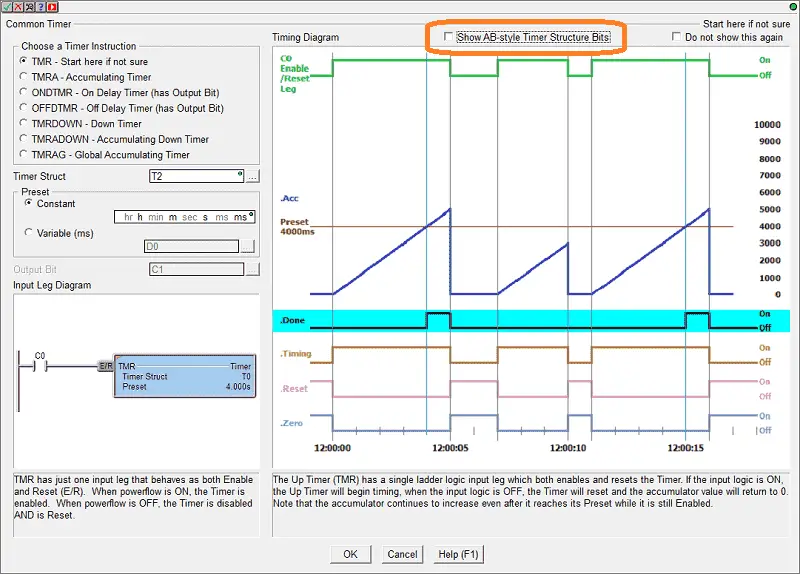
The instruction will show the timing diagram for each of the selected timer instructions. You will also see that there is an option to show the AB (Allen Bradley) style timer structure bits.
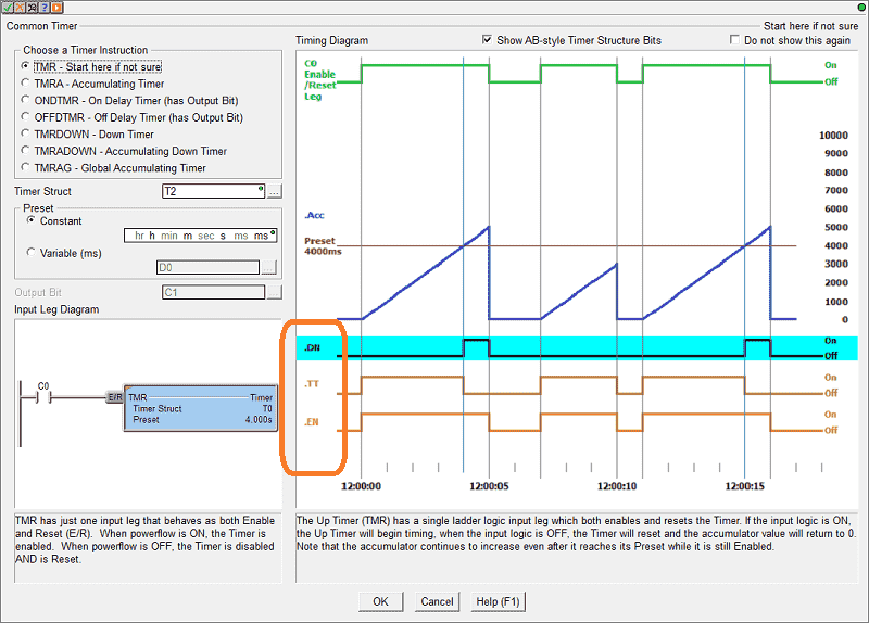
Do not get confused with some of the terminology, the timing diagram for the bits explains their function.
Timer On-Delay
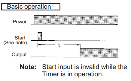
The On Delay Timer (ONDTMR) instruction is used to “delay turning on” an output by accumulating time upward from 0 toward a preset value than turning ON the output.
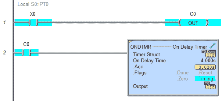
The instruction has a single ladder logic input leg that enables and resets the Timer. If the input logic is ON, the Timer is enabled and will accumulate time upward from 0 toward a preset value. When the preset value is reached, the output will come ON and remain ON until the input logic goes OFF.
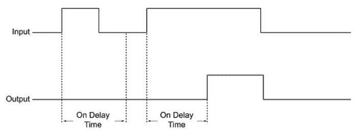
When the input logic is OFF, the Timer will reset, the Timer’s accumulator value will return to 0, and the Timer’s associated structure fields will reset. If the input logic goes OFF before the Timer preset is reached, the output will remain OFF.
Timer Off-Delay
The Off Delay Timer (OFFDTMR) instruction is used to “delay turning off” an output by accumulating time downward from a preset value toward 0 and then turning OFF the output.
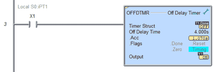
The instruction has a single ladder logic input leg that enables and resets the Timer. The Output will be latched ON when the input transitions from OFF to ON. Then, when the input logic transitions OFF, the Timer will begin timing. Once the preset value is reached, the output will turn OFF.
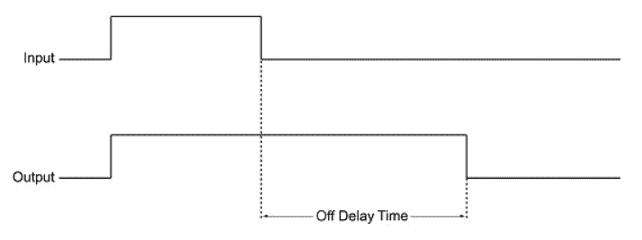
Suppose the input logic comes back ON before the preset value is reached. In that case, the output will remain ON, and the Timer will reset, meaning its accumulator will return to the preset value, and its associated structure members will be reset.
Watch the video below to see these timers in action with the timing diagrams.
PLC Counter–Timing Diagram
The Up Counter (CNT) instruction accumulates OFF to ON state changes of input logic, counting upward from 0 toward a preset value. This instruction has two of the following ladder logic inputs:
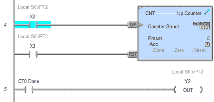
The first input is the UP Count input (UP). Each time this input logic transitions from OFF to ON, the Counter’s accumulator will increment by one. The done bit will turn ON when the accumulative value reaches the preset value.
The second input is the Count Reset (RST). When this input logic is in ON, the Counter will reset, and the Counter’s accumulator will return to 0. The Counter will remain in the reset state as long as the Reset input remains ON. The Reset input has priority over the UP Count input, meaning that if the UP Count input is ON at the same time as the Reset input, the Counter will not count.
Draw the timing diagram for this based on the information provided. Let me know how you do in the comments below. The timing diagram for the PLC counter is in the video below.
PLC Circuit Timing Diagram
A timing diagram can be used to see the PLC inputs and how they will react within the PLC ladder logic. Here is a simple PLC ladder logic rung.
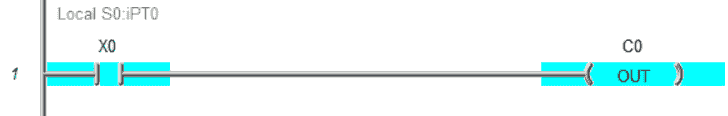
When X0 turns on, C0 turns on. Here’s the timing diagram for this simple ladder logic circuit.
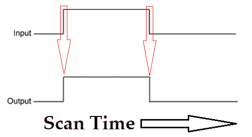
You can see that the timing diagram explains everything about the circuit without putting in many words. This will account for the output state based on the input condition. The time base rate along the X axis is in scans of the PLC program when looking at the ladder logic timing chart.
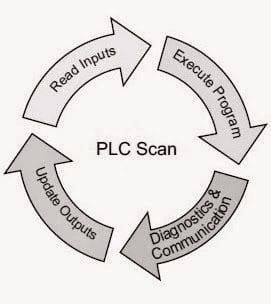
Understanding the PLC Scan
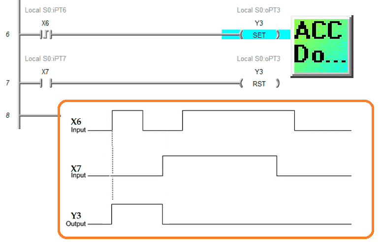
Let’s take a look at another example of a ladder logic circuit. This time we will look at a Start Stop circuit using a set and reset instruction within the PLC.
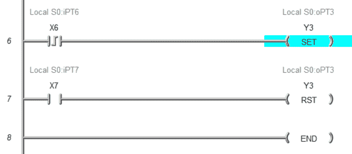
Here is my ladder logic. X6 on the leading edge will set output Y3 on the first rung. Y3 will be reset by X7 input.
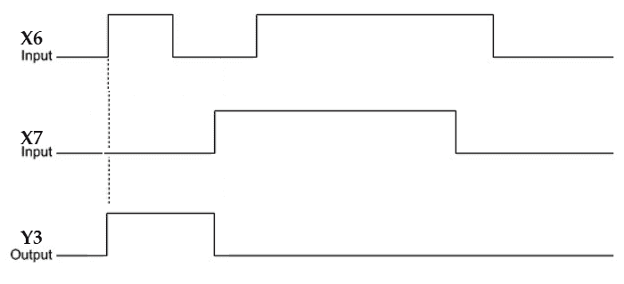
This timing chart shows you how the inputs react with the output. The timing diagram indicates that the leading edge (differential or one-shot) input will set the output. X7 will reset this output even though X6 gets triggered again. This benefits you because you know exactly how the circuit will respond in the field with every given situation. Watch the video below to see this circuit in operation.
Download the PLC ladder logic program files here. Try this ladder logic program out yourself.
Free learning and training series for PLCs.
Click / Click PLUS (Koyo)
BRX Do-More
Productivity Series
P1000
P2000
C-More EA9 Series of HMI
(Webserver, FTP, Data Logging, Free Remote Apps, etc.)
Node-Red is a free IoT software hub that can communicate MQTT and many standard industrial protocols. This series will help you communicate to the PLC, create an HMI on any electronic device, log data to a database, and view the information on a spreadsheet for analysis.
Node-RED IoT enabling Software
EasyPLC Software Suite is a complete PLC, HMI, and Machine Simulator Software package. This PLC learning package includes the following:
Easy PLC – PLC Simulation allows programming in Ladder, Grafcet, Logic Blocks, or Script.
HMI System – Easily create a visual human-machine interface (HMI)
Machine Simulator – A virtual 3D world with real-time graphics and physical properties. PLC programs can be tested using the EasyPLC or through other interfaces. (Modbus RTU, TCP, etc.)
Machine Simulator Lite – Designed to run on Android Devices.
Machine Simulator VR – Virtual Reality comes to life so you can test, train or practice your PLC programming.
Purchase your copy of this learning package for less than USD 75 for a single computer install or less than USD 100 to allow different computers.
Receive 10% off the price by typing in ACC in the comment section when you order. http://www.nirtec.com/index.php/purchase-price/
Learn PLC programming the easy way. Invest in yourself today.
Watch on YouTube: Timing Diagram NOT Just Used for a Timer
If you have any questions or need further information, please contact me.
Thank you,
Garry
If you’re like most of my readers, you’re committed to learning about technology. Numbering systems used in PLCs are not challenging to learn and understand. We will walk through the numbering systems used in PLCs. This includes Bits, Decimal, Hexadecimal, ASCII, and Floating Point.
To get this free article, subscribe to my free email newsletter.
Use the information to inform other people how numbering systems work. Sign up now.

The ‘Robust Data Logging for Free’ eBook is also available for free download. The link is included when you subscribe to ACC Automation.