Timers are one of the first things you learn about programmable logic controllers. (PLC) Just about every PLC program will include timer instructions. The Productivity 2000 Series PLC has several different timer instructions for your program. We discussed the timed coil (TMC) and flasher coil (FLS) last time as part of the ladder logic output discussion. (Ladder Logic Output Instruction – Video)
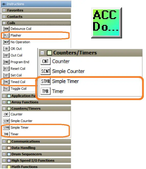 We will now look at using the Simple Timer (STMR) and the Timer (TMR) instructions in the productivity suite software. Let’s get started.
Previously in this Productivity 2000 series PLC, we have discussed:
P2000 Hardware Features – Video
Productivity Suite Software Install – Video
Communication (System Configuration) – Video
First Program – Video
Debug Mode – Video
PLC Program Documentation – Video
PLC CPU Display – Video
PLC Online Programming – Video
PLC Tag Database – Video
Ladder Logic Contacts – Video
Ladder Logic Outputs – Video
Timing Diagrams – Productivity Timer
Timers are used in the majority of PLC programs. The implementation of timers can be vast; however, it all starts with a TIMING CHART. We have covered timing charts in the following post: The Secret of Using Timers – Each post will have a corresponding YouTube video to help convey or show additional information in the post.
A timing diagram is a graphical method of showing the exact behavior of a logic circuit for every possible set of input conditions. It is often used because of its visual nature to show what is happening instead of a wordy explanation. As Fred R. Barnard stated, “A picture is worth ten thousand words.”
The timing diagram input can be either on or off. This is represented on the timing diagram on the Y axis. Time is represented on the X axis.
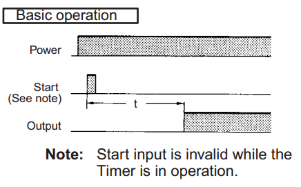 In this timing diagram, the output is off when the power is off. When power is on, and a momentary start signal is received, a timer starts timing. At the end of the time duration, the output is turned on as long as the power remains on. If the power turns off, then the output also turns off. As you can see, it is visually easier to see the timing chart than just reading how it works.
Note: There are also a wide variety of off-the-shelf industrial timers that you can use. A PLC can mimic any one of these timers easily.
Simple Timer (STMR) – On Delay Timer
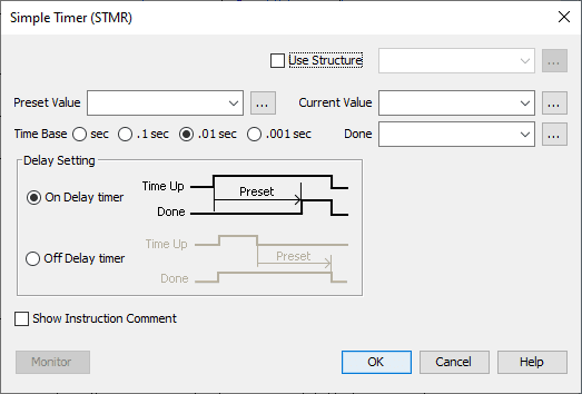
We will first use the simple timer (STMR) as an On Delay timer. The delay instruction will show you the timing diagram. This explains the operation.
 The addresses can be entered individually or through the Structure. Using the structure, the preset value, current value, and done bit are automatic.
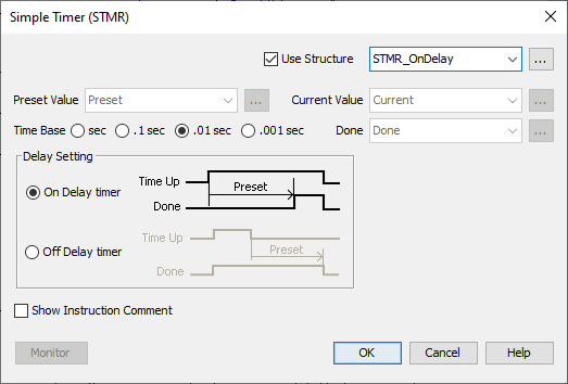 Select Use Structure. The name will be STMR_OnDelay. When we do this, the following parameters are set:
STMR_OnDelay.Current – 32bit integer
STMR_OnDelay.Done – Boolean
STMR_OnDelay.Preset – 32bit integer
The time base can be selected. We will leave this as the default of 0.01-second intervals.
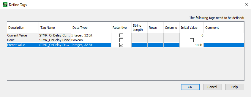 The following tags are then displayed. We will choose the preset value to be retentive and the initial value to be 1000. (1000 x 0.01 seconds = 10.00 seconds)
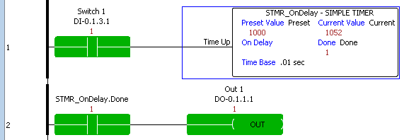 When the rung condition is on with switch 1, the timer will start to time. The timer will reset when switch 1 turns off. After the time (10 seconds) has expired, the output bit (STMR_OnDelay.Done) will turn on. The second rung of your ladder will turn on Out1 when the Done bit is on.
Simple Timer (STMR) – Off Delay Timer
Our off-delay timer will turn off the output done bit after the time set has expired. See the timing chart.
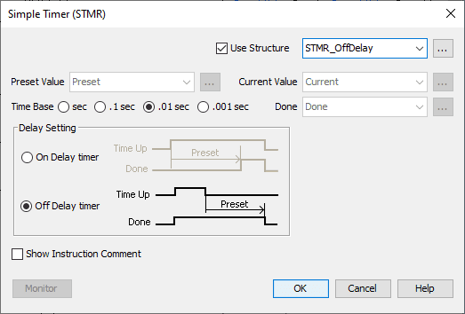 We will use the structure named STMR_OffDelay.
STMR_OffDelay.Current – 32bit integer
STMR_OffDelay.Done – Boolean
STMR_OffDelay.Preset – 32bit integer
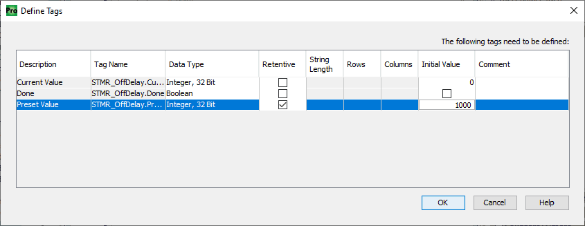 Under the defined tags, we will set the preset value to memory retentive and the initial value to 1000. (1000 x 0.01 seconds = 10.00 seconds)
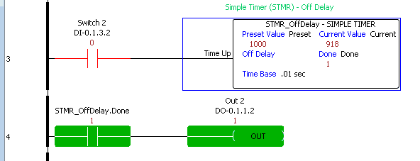 When our rung input (Switch 2) turns off, the output (STMR_OffDelay.Done) will remain on until the timer (10.00 seconds) expires. The second rung will then control the Out2 bit from the timer done bit.
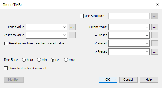
Timer (TMR) – Productivity
The timer (TMR) will accumulate a duration of time, delay a process, or time down from a specific value.
 We will use the structure name of TMR.
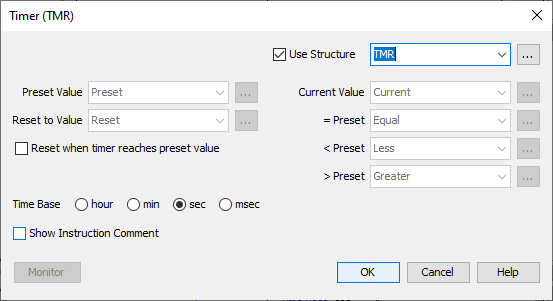 The Time Base will be left at the default setting of seconds (sec).
This will set up the following parameters:
TMR.Current – 32bit integer
TMR.Equal – Boolean
TMR.Greater – Boolean
TMR.Less – Boolean
TMR.Preset – 32bit integer
TMR.Reset – 32bit integer
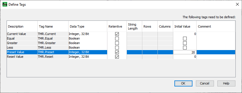 The following tags will now be defined. We will make the preset, reset, and current one’s memory retentive. The preset value will be set to 20. This represents 20 seconds for our timer.
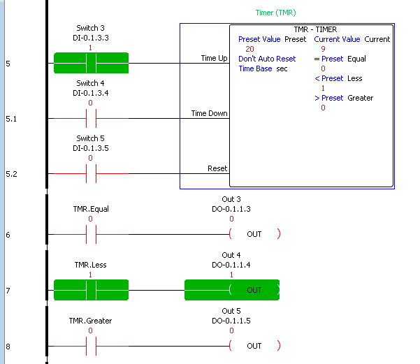 Our first input (Switch3) will be the time up. When this is on, the timer will time up at the time base rate we selected above.
The second input (Switch4) will be the time down. When this is on, the timer will time down at the time base rate. When both time up and time down inputs are on at the same time, the timer will not count.
The reset input will be done with Switch5. When this is activated, the reset value will be placed in the current value.
The outputs of the timer are set according to the comparison of the current value to the preset value of the timer. Suppose the value is equal then the TMR.Equal bit will be on. TMR.Less will be on if the current value is lower than the preset value and the TMR.Greater will be energized when the current value is more than the preset value.
Watch the video below to see the ladder logic timer instructions in our Productivity 2000 Series PLC.
Download the Productivity 2000 PLC ladder logic timer program here.
Productivity 2000 Series PLC from Automation Direct
Overview Link (Additional Information on the Unit)
Configuration (Configure and purchase a system – BOM)
User Manual and Inserts (Installation and Setup Guides)
Productivity Suite Overview (Features of the fully functional free software package for the Productivity Family of PLC (PAC) controllers)
Productivity Suite Programming Software (Free Download Link)
This software contains all the instructions and helps files for the Productivity Series.
Watch on YouTube: Productivity 2000 PLC Ladder Logic Timers
If you have any questions or need further information, please contact me.
Thank you,
Garry
If you’re like most of my readers, you’re committed to learning about technology. Numbering systems used in PLCs are not challenging to learn and understand. We will walk through the numbering systems used in PLCs. This includes Bits, Decimal, Hexadecimal, ASCII, and Floating Point.
To get this free article, subscribe to my free email newsletter.
Use the information to inform other people how numbering systems work. Sign up now.

The ‘Robust Data Logging for Free’ eBook is also available for free download. The link is included when you subscribe to ACC Automation.