The EasyPLC palletizing robot will demonstrate sequencing and robot control using a PLC. This palletization process will fill a box container with six cans. A servo-controlled gantry robot using x and y is used to do this operation. The complete box will then travel along to another conveyor to an unloading area. A robot will then pick up the box and place this on a pallet.
 We will discuss and show you how to program this EasyPLC palletizing robot machine using the five steps for PLC program development. This will involve all the ladder logic to load and unload using the robot simulator. This PLC simulator will show sequencing instructions. A drum instruction in the PLC will be used with events and a counter to load the box with six cans. Another drum instruction in the PLC, with time, will be used to unload the container onto a pallet. An Automation Direct Click PLC will be used for this application, but the general methods can be used for just about any PLC on the market. Serial Modbus RTU communication between the machine simulator and the Click PLC will be used. An Ethernet connection will be used with the Click programming software. Let’s get started.
Learn PLC programming the easy way. See below how to receive a 10% discount on this already cost-effective learning tool. Invest in yourself today.
Previously we have done the following:
Easy PLC Installing the Software – Video
EasyPLC Software Suite – Quick Start – Video
Click PLC – Easy Transfer Line Programming – Video
Productivity PLC Simulator – Chain Conveyor MS – Video
Do-More PLC – EasyPLC Box Selection Program – Video
Click PLC EasyPLC Gantry Simulator – Video
Click PLC Simple Conveyor EasyPLC – Video
EasyPLC Paint Line Bit Shift – BRX Do-More PLC – Video
Click PLC – EasyPLC PLC Mixer Programming – Video
Click PLC EasyPLC Warehouse Stacker Example – Video
– Operation Video
EasyPLC Machine Simulator Productivity PLC Robotic Cell – Video
EasyPLC Simulator Robotic Cell Click PLC – Video
EasyPLC Simulator Robotic Cell BRX Do-More PLC – Video
– EasyPLC Factory Editor Robotic Cell Additions Video
4 Way Traffic Light PLC Program EasyPLC – Video
Rock Crusher Plant EasyPLC BRX Do-More – Video
Freight Carrier Weighing and Distribution EasyPLC – Video
EasyPLC Machining Center Loading Robots – Video
Define the task: (Step 1 – EasyPLC Palletizing Robot)
The first step of PLC program development is defining the task to determine what must be done. EasyPLC software suite contains this palletizing robot example in the machine simulator. This is just one of many machines that come with the software so you can learn and develop your PLC programming skills.
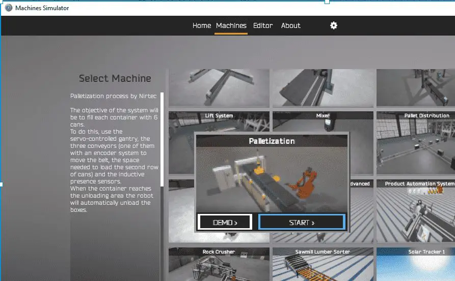
The system’s objective will be to fill each container with six cans. To do this, use the servo-controlled gantry, the three conveyors (one with an encoder system to move the belt, the space needed to load the second row of cans), and the inductive presence sensors. The robot will automatically unload the boxes when the container reaches the unloading area.
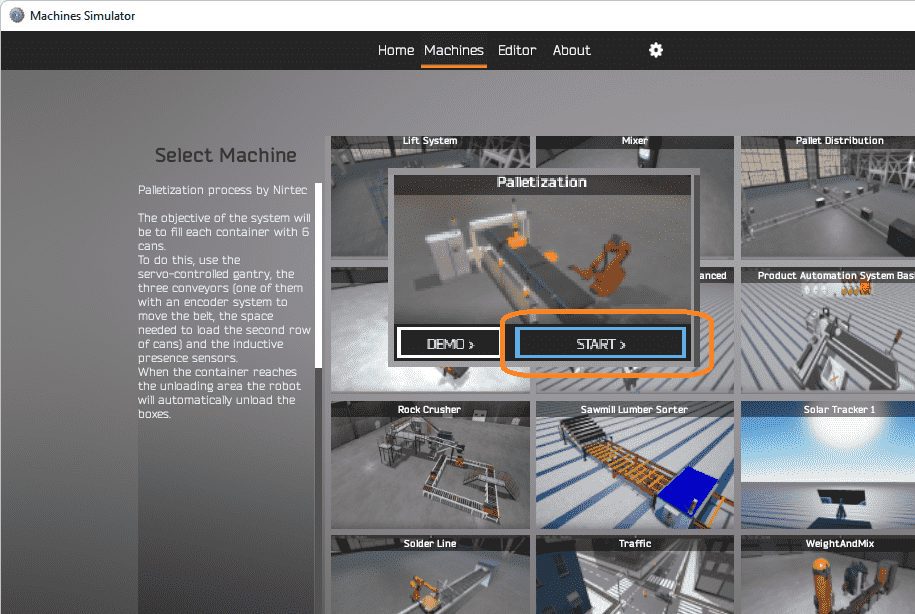
Start the EasyPLC Machine Simulator (MS). Select the start button on the main page or select machines from the main menu on the top of the machines simulator window.
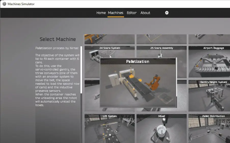 All the available machines will now be displayed. Click on the “Palletization.”
This is the example that we will be programming. To the left of the screen, information will be displayed on how the palletizing robot needs to function.
This is printed above.
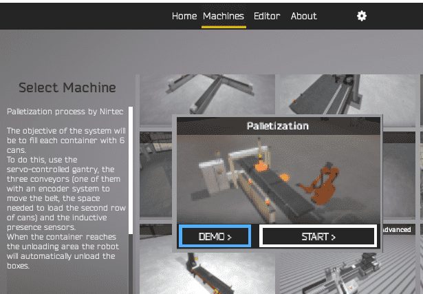 The machine simulator has a demo mode for the built-in machines. This will allow you to watch the operation of the palletizing robot. Select the demo mode.
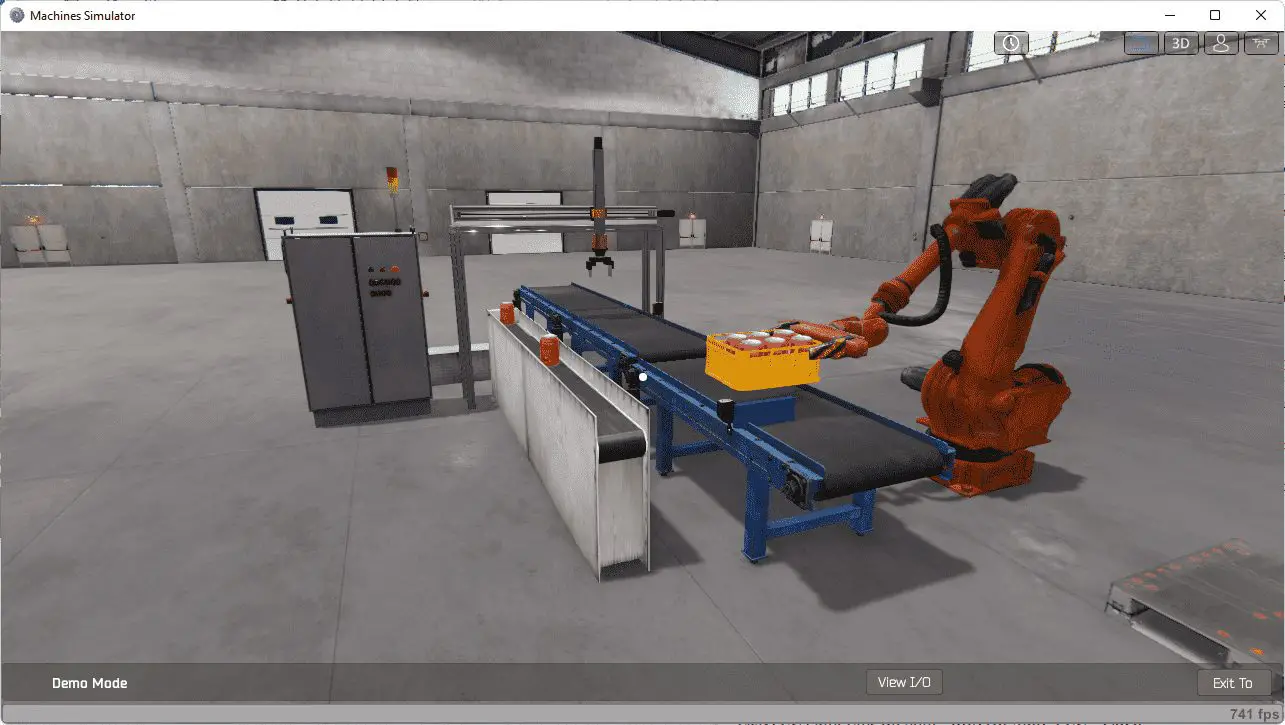 The EasyPLC palletizing robots demo mode on the machine simulator will show you the basics of operation.
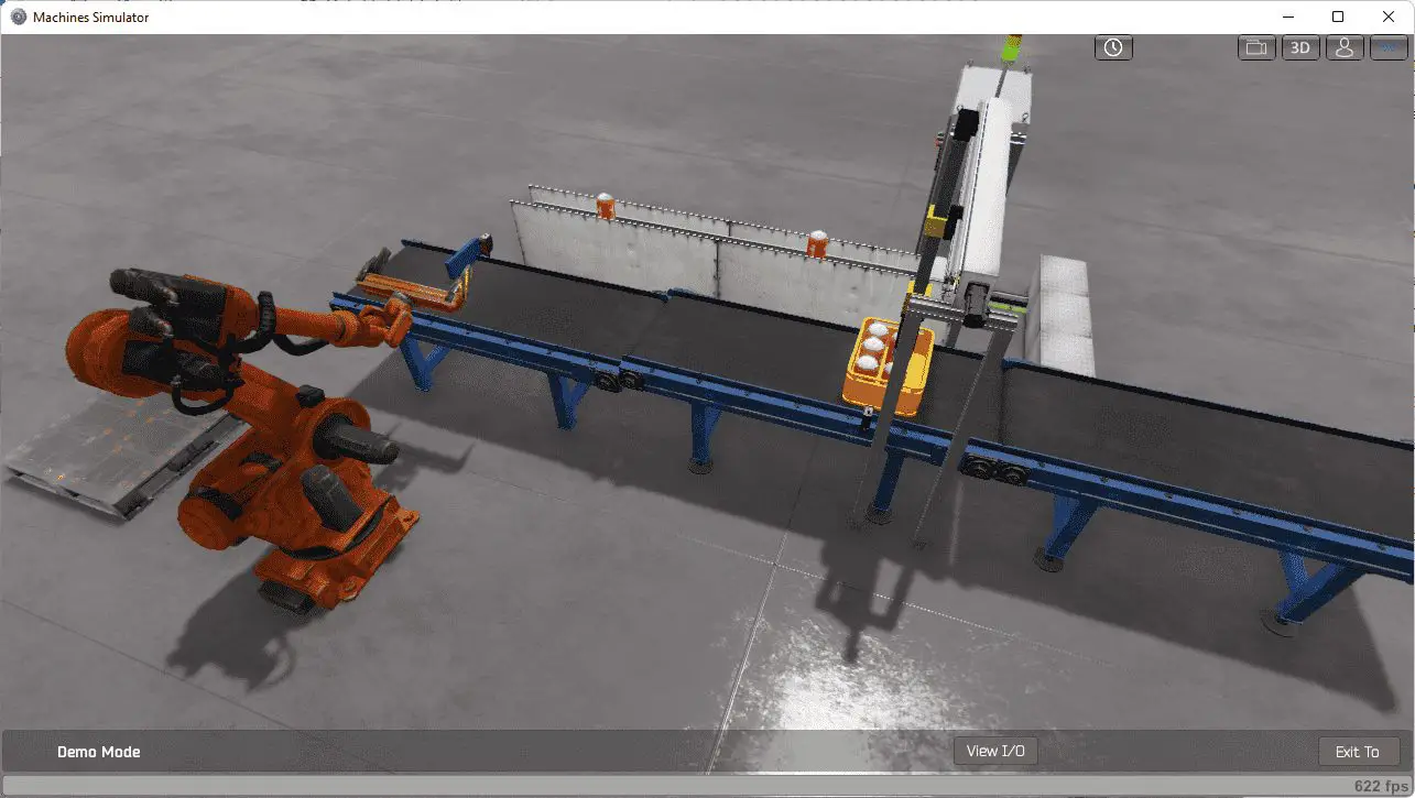 Move around the 3D virtual environment. Three icons on the top of the window will allow you to move around this 3D environment. The first icon is the default selection. This will enable you to move around without bumping into the components. The last icon will automatically show you around this virtual environment. The first-person mode will mimic a person in your 3D learning world. Once we understand what must be done, we can move on to the next step in our PLC program development.
Define the Inputs and Outputs: (Step 2 – EasyPLC Palletizing Robot)
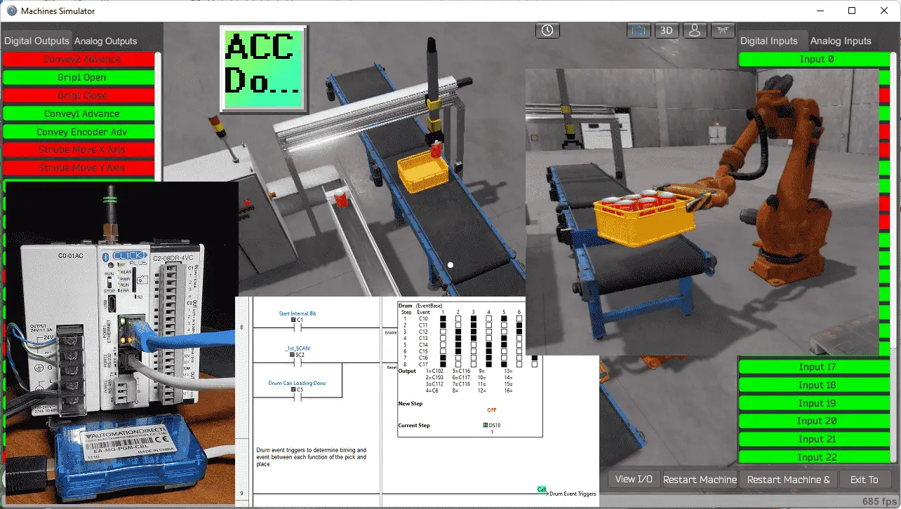
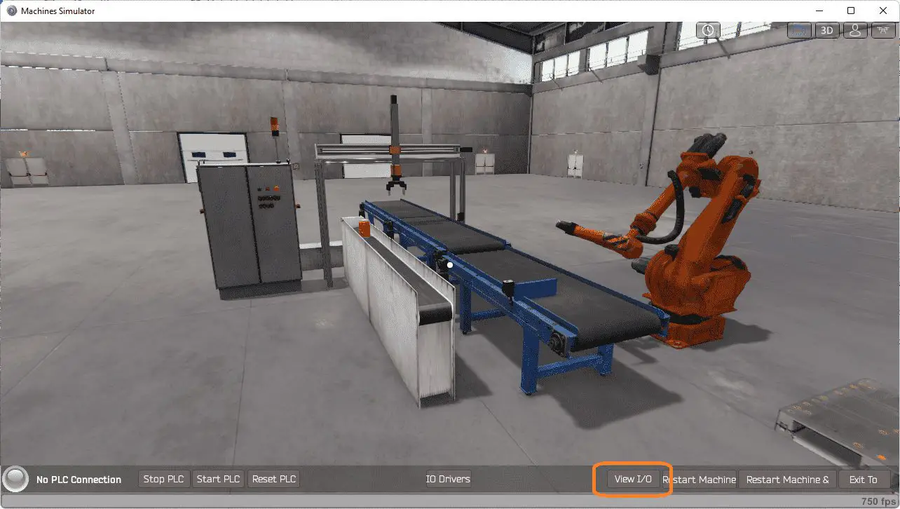
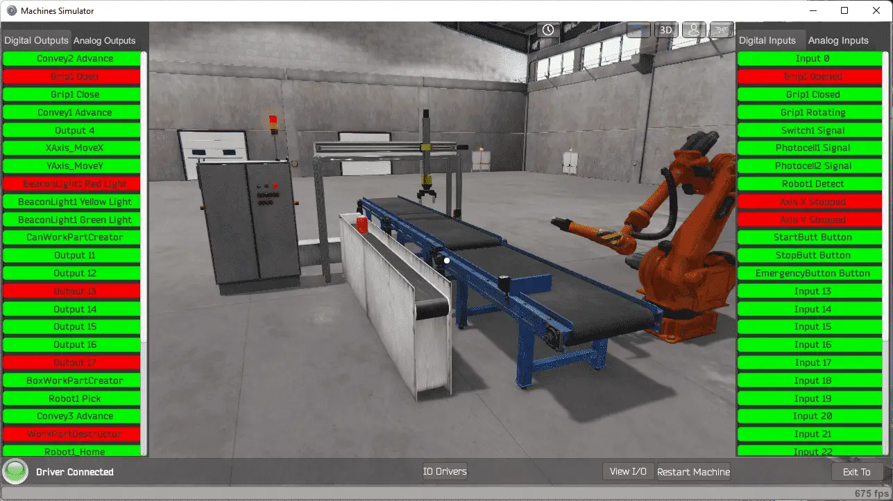
The View IO at the bottom of the machine simulator window will display the inputs and outputs required for this palletizing robot example. While still in demo mode, you can see the operation of the inputs and outputs.
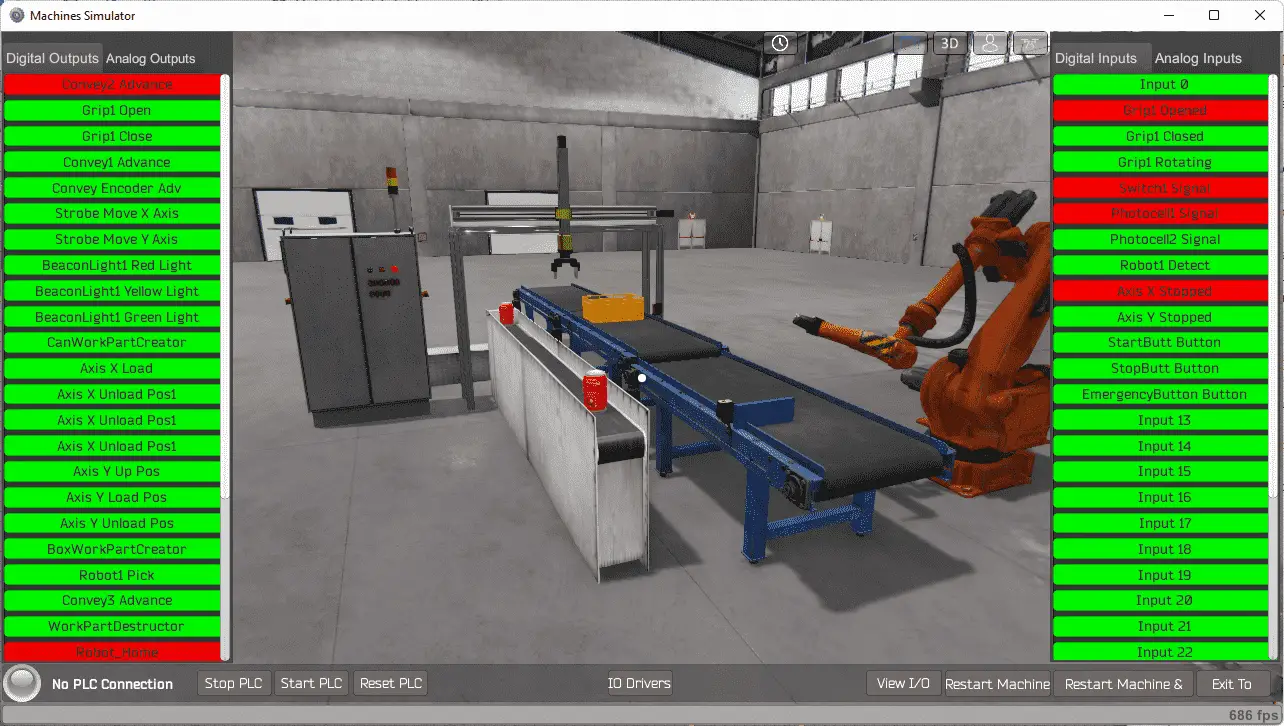
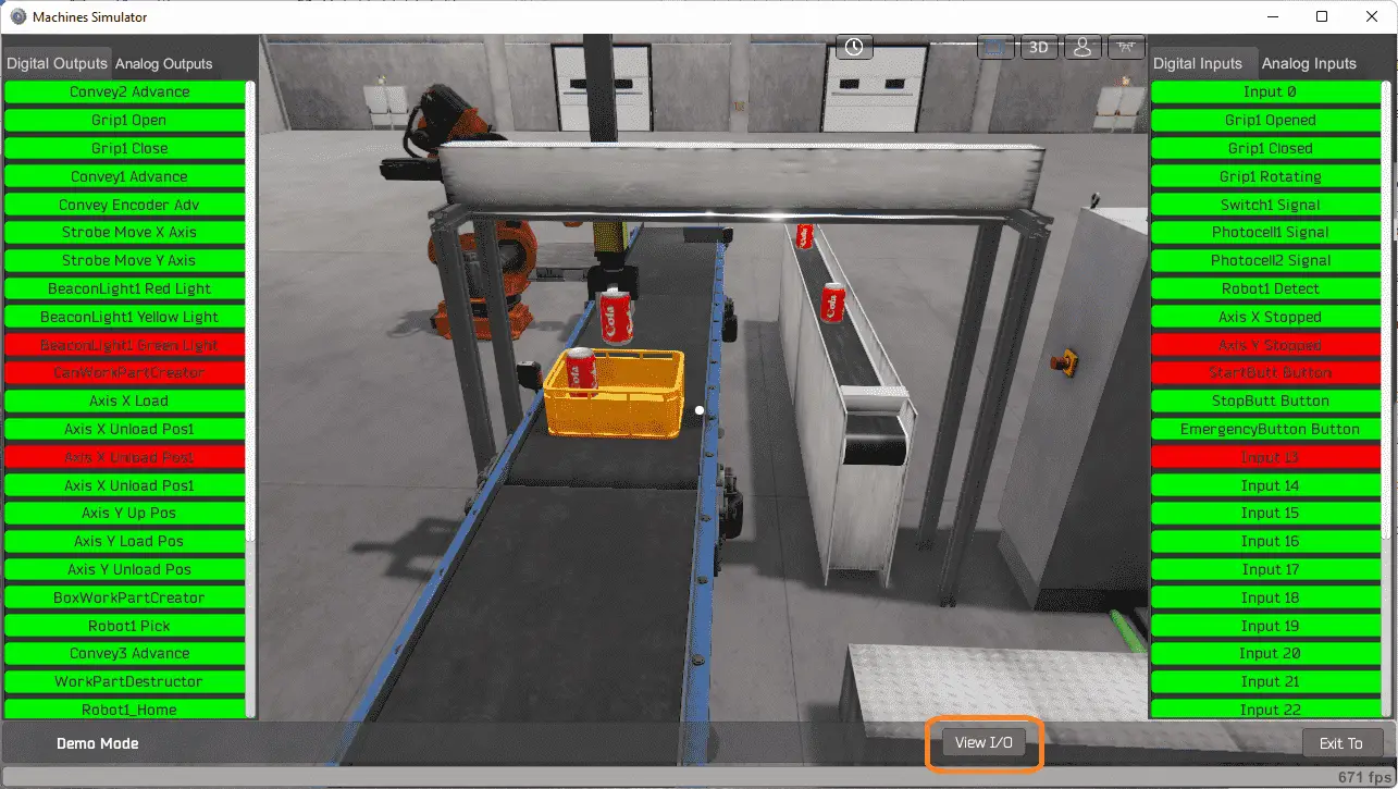 The EasyPLC palletizing robot example will require 15 digital outputs and 12 digital inputs.
 The EasyPLC start mode will allow you to control the machining center simulator manually.
 This is ideal if you are unsure what output or input is doing.
 Select the “View IO” on the bottom middle of the machine simulator window. You can manually run the machine simulator without any control or PLC connection.
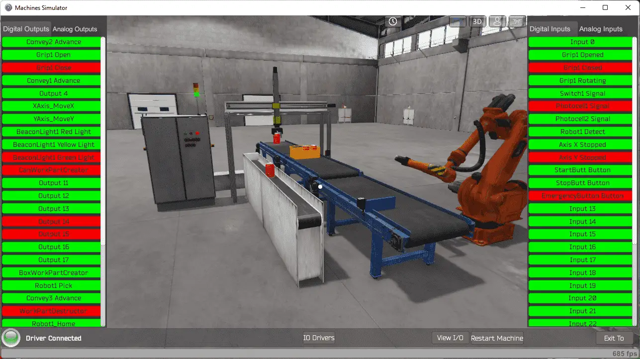
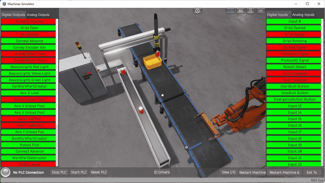 You can now use select and start the palletizing robot digital outputs on the left side of the screen by clicking on them with the mouse. The right side will show you the corresponding digital inputs. The restart button on the bottom of the machine simulator window will reset the scene back to the start.
Move around the 3D environment and ensure you know what each input and output represents.
The following table will define the inputs and outputs (IO) and Modbus addresses in the Click PLC that we will use for this program.
| Digital Type | Description | Click PLC Modbus Address | Machine Simulator Modbus Address |
| PLC Output – MS Input | Conveyor2 Advance | C101 – 16485 | 16484 |
| PLC Output – MS Input | Grip 1 Open | C102 – 16486 | 16485 |
| PLC Output – MS Input | Grip 1 Close | C103 – 16487 | 16486 |
| PLC Output – MS Input | Conveyor1 Advance | C104 – 16488 | 16487 |
| PLC Output – MS Input | Conveyor Encoder Advance | C105 – 16489 | 16488 |
| PLC Output – MS Input | Strobe Move X-Axis | C106 – 16490 | 16489 |
| PLC Output – MS Input | Strobe Move Y-Axis | C107 – 16491 | 16490 |
| PLC Output – MS Input | Beacon Red Light | C108 – 16492 | 16491 |
| PLC Output – MS Input | Beacon Yellow Light | C109 – 16493 | 16492 |
| PLC Output – MS Input | Beacon Green Light | C110 – 16494 | 16493 |
| PLC Output – MS Input | CanWorkPartCreator | C111 – 16495 | 16494 |
| PLC Output – MS Input | Axis X Load | C112 – 16496 | 16495 |
| PLC Output – MS Input | Axis X Unload Position 1 | C113 – 16497 | 16496 |
| PLC Output – MS Input | Axis X Unload Position 2 | C114 – 16498 | 16497 |
| PLC Output – MS Input | Axis X Unload Position 3 | C115 – 16499 | 16498 |
| PLC Output – MS Input | Axis Y Up Position | C116 – 16500 | 16499 |
| PLC Output – MS Input | Axis Y Load Position | C117 – 16501 | 16500 |
| PLC Output – MS Input | Axis Y Unload Position | C118 – 16502 | 16501 |
| PLC Output – MS Input | BoxWorkPartCreator | C119 – 16503 | 16502 |
| PLC Output – MS Input | Robot 1 Pick | C120 – 16504 | 16503 |
| PLC Output – MS Input | Conveyor3 Advance | C121 – 16505 | 16504 |
| PLC Output – MS Input | WorkPartDistructor | C122 – 16506 | 16505 |
| PLC Output – MS Input | Robot 1 Home | C123 – 16507 | 16506 |
| PLC Output – MS Input | Robot 1 Take | C124 – 16508 | 16507 |
| PLC Output – MS Input | Robot 1 Takeup | C125 – 16509 | 16508 |
| PLC Output – MS Input | Robot 1 PreDownload | C126 – 16510 | 16509 |
| PLC Output – MS Input | Robot 1 Download | C127 – 16511 | 16510 |
| PLC Input – MS Output | Input 0 (Not Used) | C201 – 16585 | 16584 |
| PLC Input – MS Output | Grip 1 Opened | C202 – 16586 | 16585 |
| PLC Input – MS Output | Grip 1 Closed | C203 – 16587 | 16586 |
| PLC Input – MS Output | Grip 1 Rotating | C204 – 16588 | 16587 |
| PLC Input – MS Output | Switch 1 Signal | C205 – 16589 | 16588 |
| PLC Input – MS Output | Photocell 1 Signal | C206 – 16590 | 16589 |
| PLC Input – MS Output | Photocell 2 Signal | C207 – 16591 | 16590 |
| PLC Input – MS Output | Robot 1 Detect | C208 – 16592 | 16591 |
| PLC Input – MS Output | Axis X Stopped | C209 – 16593 | 16592 |
| PLC Input – MS Output | Axis Y Stopped | C210 – 16594 | 16593 |
| PLC Input – MS Output | Start Button | C211 – 16595 | 16594 |
| PLC Input – MS Output | Stop Button | C212 – 16596 | 16595 |
| PLC Input – MS Output | Emergency Stop Button | C213 – 16597 | 16596 |
Note: The machine simulator will be offset by one on the Modbus Addresses. See the video below for the demo mode and determining inputs and outputs.
Develop a logical sequence of operation: (Step 3 – EasyPLC Palletizing Robot)
A PLC programmer must know how everything about the sequence and operation of the machine before programming. The palletizing robot simulator is an excellent way to learn to program. Flow charts or sequence tables can be used to understand the process that needs to be controlled thoroughly. It must also answer questions like the following:
What happens when electrical power and pneumatic air is lost? What happens when the input/output devices fail? Do we need redundancy?
This step is where you will spend most of your time. Understanding everything about the operation will save you time. It will help prevent you from continuously re-writing the PLC program logic. Knowing all these answers to how the system is to react is vital in developing the PLC program. This does not have to be a formal document. You have to have a method to account for every condition in the machine being programmed.
Our EasyPLC palletizing robot is split up into several different sections. We will walk through the logical sequence of operation.
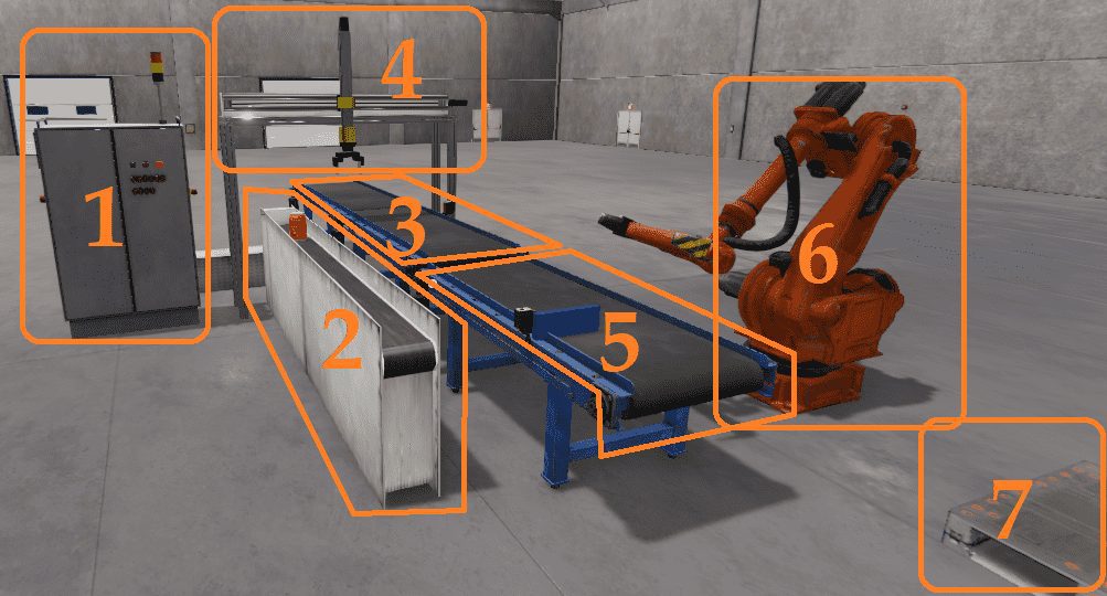 Splitting the requirements up into smaller sections will allow you to concentrate on the task and not get distracted by other parts of the program that are unrelated.
Section 1 – Start, Stop, Emergency Stop, Beacon Lights
If the emergency stop input is not on, the red light will flash at 1-second intervals. When the E-Stop is on, it will allow the palletizing robot to start and stop the operation. The start push button will start the machine, and the green light will be on. The stop push button will stop the operation of the machine, and the red light will be on.
Section 2 – Can Creation
If switch 1 is not on, then no can is present. Turn on the can conveyor to make the cans to fill the box. This will all happen if the machine is started.
Section 3 – Conveyors 2 and 1. Box Creator
Both conveyors will run when the palletizing robot machine runs, and no box is detected with photocell one on conveyor 1. The box creator will be activated for a time duration to make a new box. The conveyors will stop when this new box is seen at photocell 1. After filling the pack with six cans, conveyor one will start and put the whole package on conveyor 3. When the box leaves the photocell 1 sensor, a new container is created again.
Section 4 – Loading cans into the box
This section will load the cans into the box. We are using drum instruction for this operation. It uses a sequence table with events for each step. One complete pass through the drum will indicate one can get into the box. A counter is used to keep track of the number of cans and when the conveyor will need to index to the next row.
Section 5 – Conveyor 3 control
When the box is full, conveyor three will be turned on until photocell 2 is on. This indicates that it has reached the unloading area.
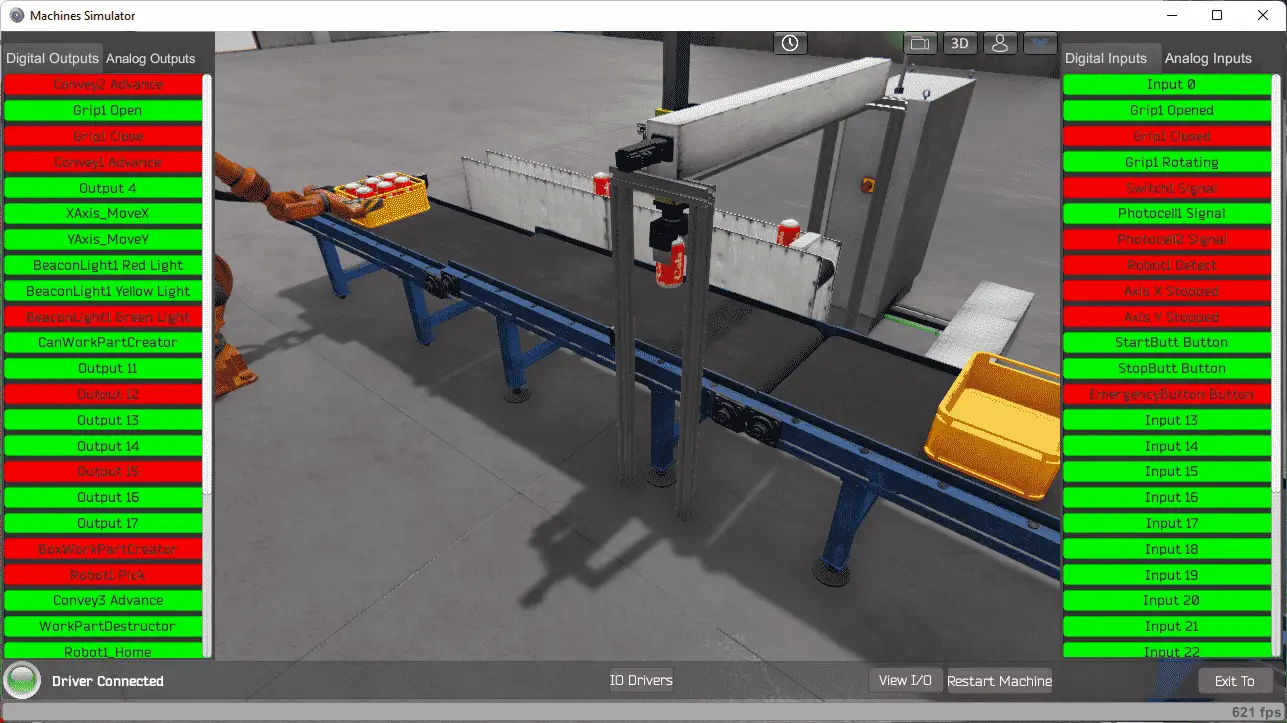
Section 6 – Robot to load the pallet
A robot will be controlled at the unload area with another drum instruction. This drum will use time events to move to the next step. These are pre-programmed steps in the robot that get triggered by the PLC output.
Section 7 – Full Box on Pallet Destructor
The cans will disappear when the whole box of cans is placed on the pallet, and the robot moves back to the home position. This will allow additional packages to be palletized.
A PLC programmer must know how everything about the sequence and operation of the machine before programming.
Ask questions or view existing documentation to ensure that you know the logical steps to the machine operation. Writing out what is supposed to happen will help to clarify what is required in the PLC program. This is just another method like flow charts and sequence tables.
Develop the Click PLC program: (Step 4 – EasyPLC Palletizing Robot)
Using the information from the previous step, we can now program our Click PLC. The Click PLC Series will take you through installing the program, communicating to the controller instructions, and addressing the controller.
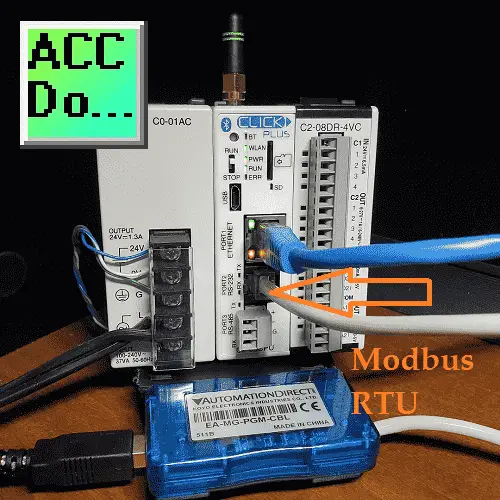 We are using the serial port of our computer to communicate to the Click PLC. This will use the USB to RS232 adapter. (EA-MG-PGM-CBL)
Windows Driver Link – (Windows 2000 SP4, Windows XP SP2, and Windows Vista(32/64 bit), Windows 7 (32/64 bit), Windows 8 and 8.1 (32/64 bit), Windows 10)
Application Note: Windows 10 / 11
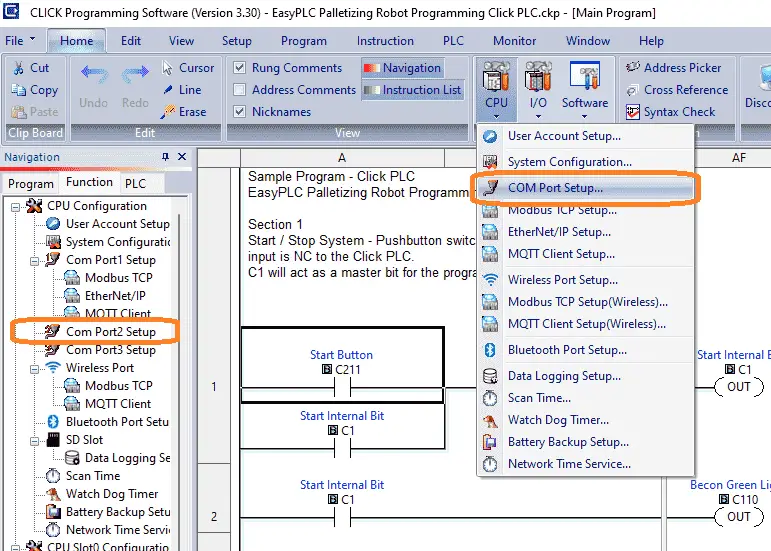 On the Click PLC programming software, select the com port setup under the PLC on the main menu. You can also call the specific communication ports by selecting them in the CPU configuration on the function tab.
 Select the setup button under port 2. You will notice that the port assignments are printed on the PLC itself. A picture of the CPU module is also shown.
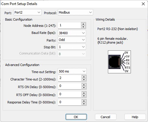 We will leave everything as their default in the com port setup details window. The essential items are the node address, baud rate, parity, stop bits, and communication data bits. We will need this information to connect to our EasyPLC machine simulator. Select Port 1.
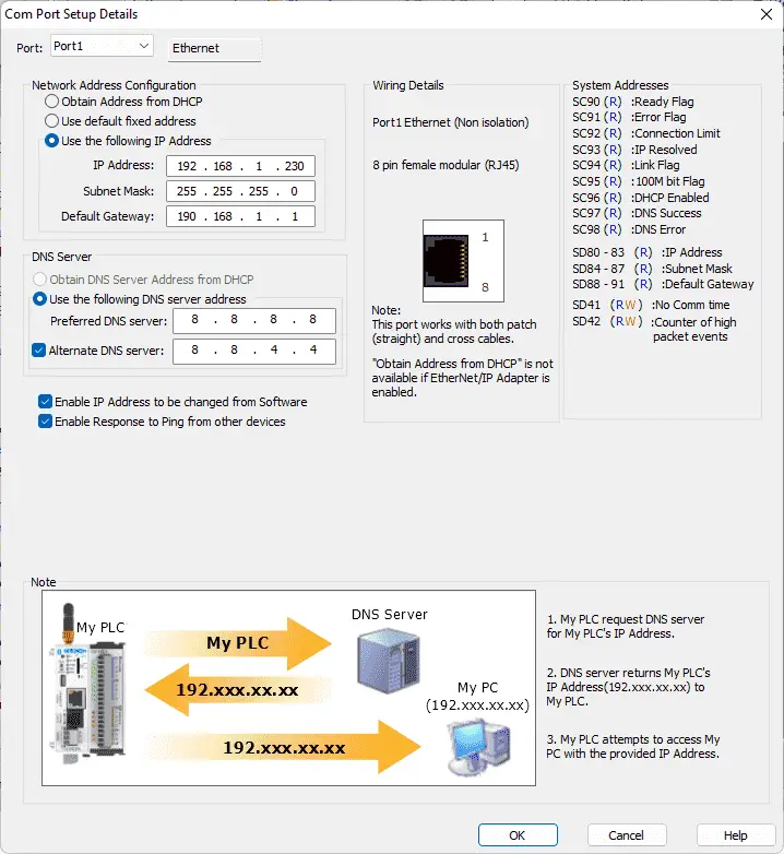 This will display our Ethernet port setup on the Click PLC. Use a static IP address that is appropriate for your network. Select OK.
We have our communication ports set. Let’s now look at the ladder logic programming of each section. We will monitor the machine simulator so you can see the ladder logic function as we look at the code.
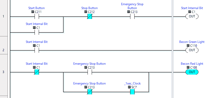 Here is the logic for section 1. As you can see, the red beacon light is flashing, indicating that the emergency stop button is not satisfied. An internal start bit (C1) controls the rest of the logic.
Selecting the emergency stop button will then turn the red beacon light on all the time. The start and stop buttons control our internal start bit and lights.
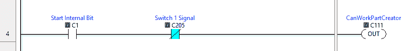 Section 2 will control the can creator. The cans are created when the internal start bit is on and switch one signal is not on. This will then turn on the can work part creator. Once a can is at switch 1, the conveyor will stop.
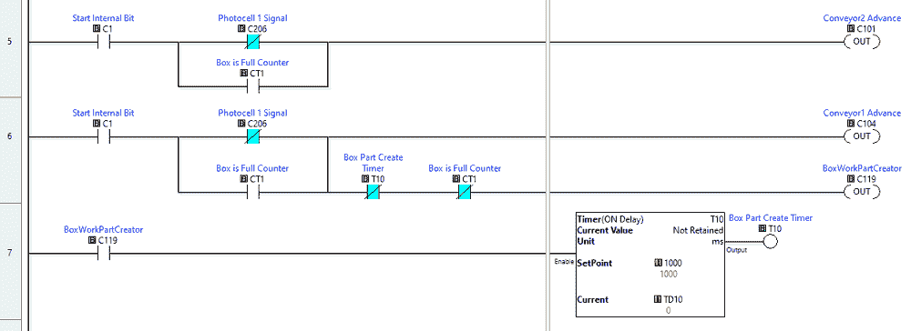 Section 3 will control conveyors 2 and 1. It will also control the box work, part creator. A timer is used for the box creator as a one-shot of 1 second.
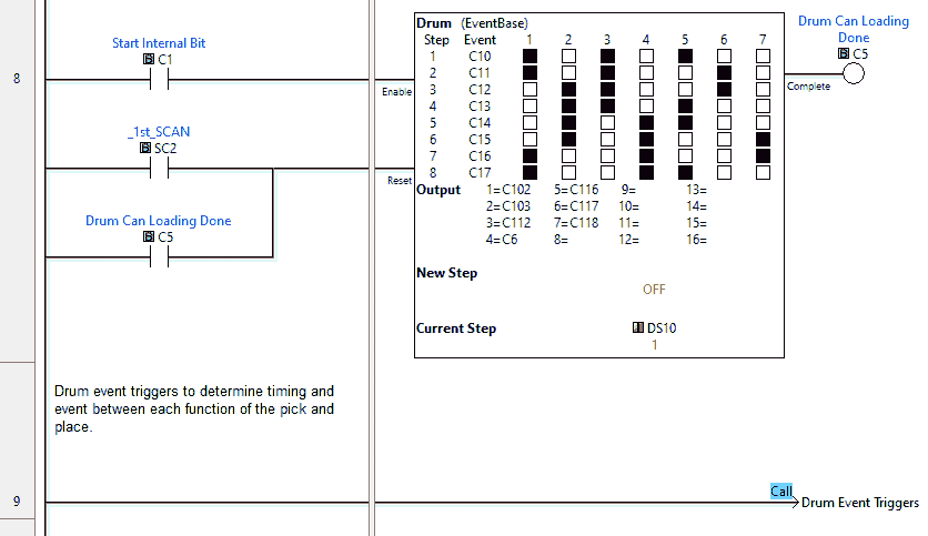 Section 4 will control the can pick and place. This is controlled using an event drum instruction. The drum enabled is done with the start internal bit. Resetting the drum is accomplished with the first scan of the PLC or by each pass of the drum instruction. One sequence through the drum will put one can into the box.
The drum events are controlled through a subroutine called drum event triggers. This subroutine will control the individual bits C10 to C17.
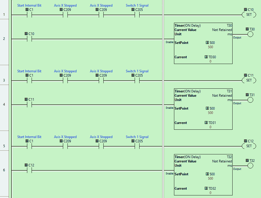
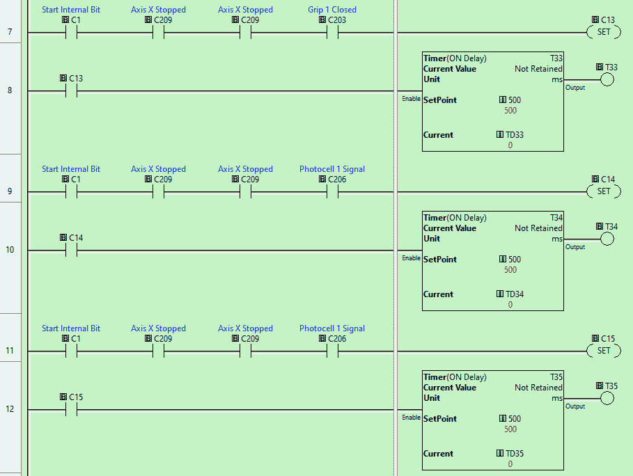
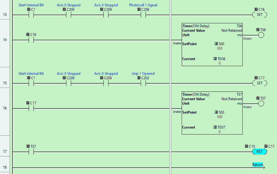 The drum event trigger bit is controlled by individual bits for that step. A timer is also used to allow the axis movement to happen.
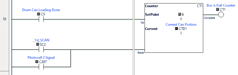 A counter is used for the event drum instruction. This will count the number of cans in the box to determine if it is full.
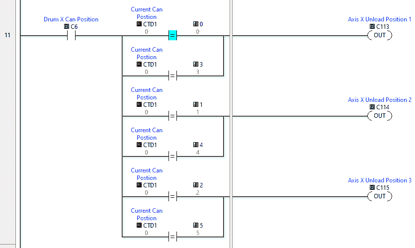 The counter is also used to determine the position to place the can into the box. Unload position 1 will happen at counter values 0 and 3. Position 2 will occur at counter values 1 and 4. Unload position 3 will happen at counter values 2 and 5.
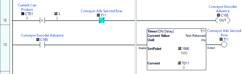 The conveyor encoder’s advanced output will allow us to move to the second row in the box. When the current can position is 3 on the counter, the conveyor’s advance output will be on for 1 second.
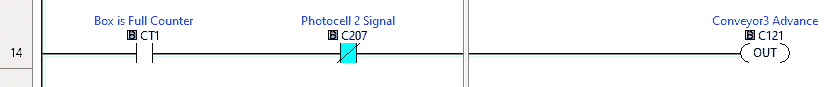 Section 5 will control conveyor 3. When we have a full box, the counter bit will be on. If there is no box at photocell 2, then conveyor 3 will be on until the full box reaches photocell 2.
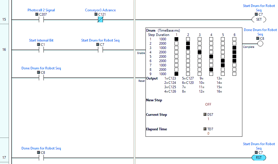 A time-based drum instruction is used in section 6. This will make the robot pick up the full box of cans and place them on the pallet. C7 and C1 are internal bits used to enable the drum instruction. The drum instruction is reset when it performs the sequence of events once. The timing of the sequence can be seen in the drum instruction itself.
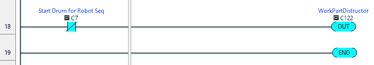 Section 7 is used to make the full box disappear on the pallet. This will allow the machine to load another box. When the robot drum sequence is not running, the work part destructor output is turned on. Our ladder logic program is complete. Download the program to the Click PLC. Ensure that the controller is in run mode.
Watch the video below to see this Click PLC program in action.
Test the program: (Step 5 – EasyPLC Palletizing Robot)
We will use Modbus RTU on our Click PLC to communicate to the EasyPLC Machine Simulator.
Call up the palletization robot in start mode.
 The status of the machine simulator will be along the bottom of the screen.
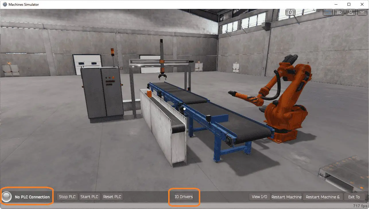 Currently, we have no PLC connected. Select IO Drivers on the bottom middle of the screen.
The EasyPLC driver is selected by default. Under the driver pull-down menu, select “ModBusDriver.” This driver will communicate Modbus TCP (Ethernet) and Modbus RTU (Serial). Select the down arrow on the driver’s name.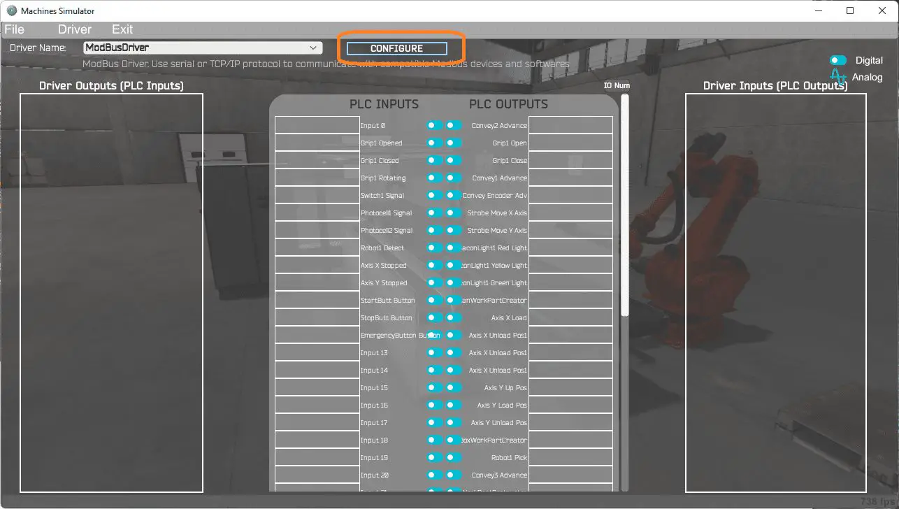 Select the configure button.
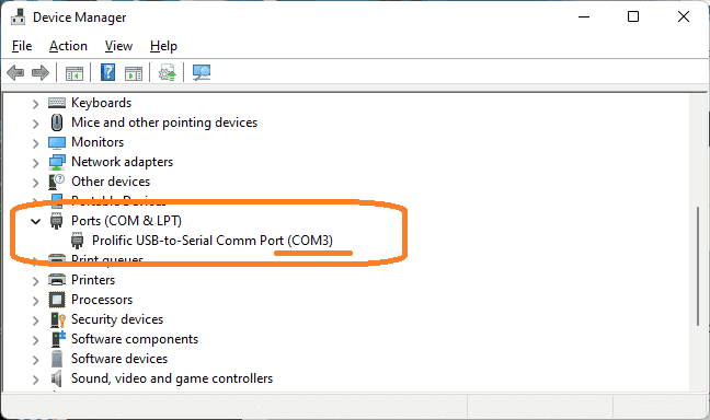
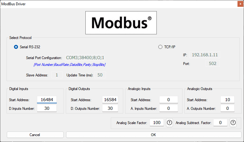 We can now enter the information for our Modbus RTU driver. Select Serial RS-232. This means the computer’s COM port will communicate to the PLC. Call the device manager on your Windows computer to determine the COM port number.
 Type in the serial port configuration to the same parameters that we have set in the Click PLC. The EasyPLC will be the Modbus Master (Client) to the Click PLC Modbus Slave (Server).
The digital inputs from MS to the Click PLC will be C101 to C131. This will start at address 16484 due to the offset of 1. Digital outputs from MS to the Click PLC will be C201 to C231. This will begin at address 16584 due to the offset of 1. Ensure that we have the number of inputs and outputs addresses for our application. This has been set for more in our application. We do not use analog inputs and outputs for the palletizing robot program. Select the OK button.
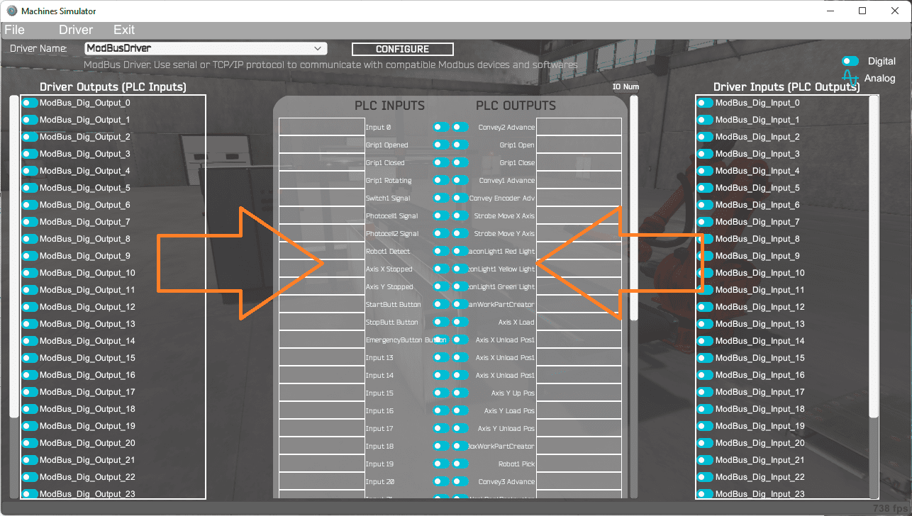 You will now see the inputs and outputs specified for the Modbus driver. We can manually assign the driver outputs to the PLC inputs and the driver inputs to the PLC outputs. However, the automatic assignment works well and will save you time.
 Select Automatic Assignment from the driver option in the main menu. This will automatically assign the PLC IO to the Machine Simulator IO.
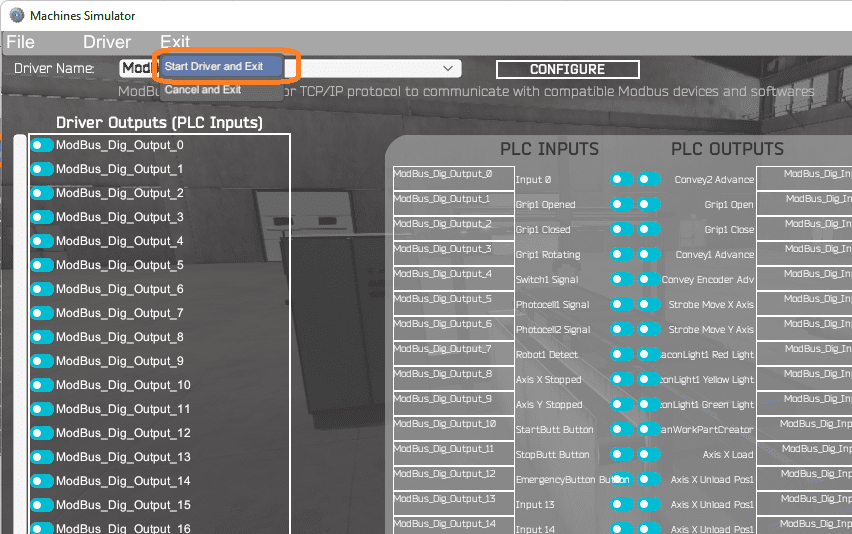 Select start driver and exit from the main menu.
 On the bottom left side of the window, you will see that the driver communicates to the PLC by the green light. Select view IO to know the input and output status of the machine simulator.
 Ensure that the PLC is in run mode. We can see the operation of our EasyPLC palletizing robot program.
 Move around this 3D environment and ensure that the program is functioning correctly. This is where you can troubleshoot and correct errors in your program.
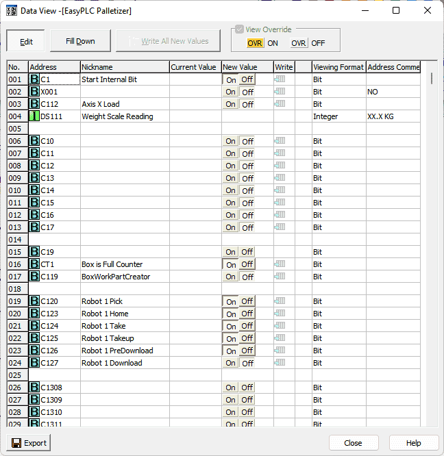 We can also watch the inputs and output operations using the Data View window of the Click PLC programming software.
Watch the video below to see this on the operation.
If your program works correctly, it’s time to move on. If not, you’ll need to debug. This can be as simple as re-downloading and re-uploading your program or as complicated as re-designing your logic altogether. When using EasyPLC, debugging is quickly done with no damage to any equipment. You may modify your logic several times before you get everything right! That’s okay—it’s all part of learning.
You can practice your modification and debug by modifying the palletizing robot in the following way:
– Add a reset button on the control panel. This will let the PLC know that all the boxes and cans have been removed from the conveyors.
Let me know how you make out in the comments below.
The essential operation of the machine works; however, we did discover an error that does exist. Can you find it? Comment below.
Download the EasyPLC Palletizer and Click PLC sample programs here.
Watch the video below to see the five steps of program development applied to the palletizing robot. The machine simulator is one of the best applications to help you learn PLC programming.
EasyPLC Software Suite is a complete PLC, HMI, and Machine Simulator package. This PLC learning package includes the following:
Easy PLC – PLC Simulation allows programming in Ladder, Grafcet, Logic Blocks, or Script.
HMI System – Easily create a visual human-machine interface (HMI)
Machine Simulator – A virtual 3D world with real-time graphics and physical properties. PLC programs can be tested using the EasyPLC or through other interfaces. (Modbus RTU, TCP, etc.)
Machine Simulator Lite – Designed to run on Android Devices.
Machine Simulator VR – Virtual Reality comes to life so you can test, train or practice your PLC programming.
Purchase your copy of this learning package for less than USD 75 for a single computer install or less than USD 100 to allow different computers.
Receive 10% off the price by typing in ACC in the comment section when you order. http://www.nirtec.com/index.php/purchase-price/
Learn PLC programming the easy way. Invest in yourself today.
Watch on YouTube: EasyPLC Machining Center Loading Robots
If you have any questions or need further information, please contact me.
Thank you,
Garry
If you’re like most of my readers, you’re committed to learning about technology. Numbering systems used in PLCs are not challenging to learn and understand. We will walk through the numbering systems used in PLCs. This includes Bits, Decimal, Hexadecimal, ASCII, and Floating Point.
To get this free article, subscribe to my free email newsletter.
Use the information to inform other people how numbering systems work. Sign up now.

The ‘Robust Data Logging for Free’ eBook is also available for free download. The link is included when you subscribe to ACC Automation.