Timing Diagram NOT Just Used for a Timer
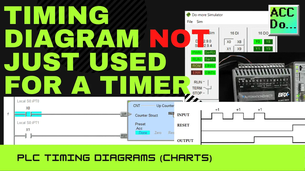
Logic circuits in a PLC ladder logic program are either on or off. The inputs change, which will affect the outputs. This can be expressed in a timing diagram. The timing diagram or chart will show you how the ladder logic program will respond to the changing states of the inputs and outputs. This visual … Read more