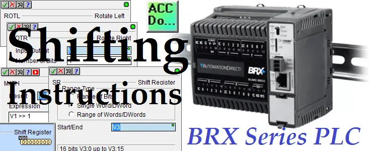
We will now look at shifting instructions in the BRX Do-More controller. PLC shifting instructions will move bits in memory areas a fixed amount when instructed. Bits are on/off, 1 or 0, and are usually associated together to form a memory location. The memory location can be used for numbers or positions.
PLC BITS NUMBERS AND POSITION is a post that will review the different methods that the PLC will interpret the information in memory
We will be looking at the shifting (moving) of the bits within the memory location in several different ways. ROTL rotate left, ROTR rotate right, Math shift left operator, Math shift right operator, Math unsigned shift right operator and SR shift register are some of the instructions in our BRX Do-More PLC that will shift bits.
Let’s look at some samples of each of the above-mentioned instructions.
Previously in this BRX Do-More series PLC, we have discussed:
System Hardware – Video
Unboxing – Video
Installing the Software – Video
Establishing Communication – Video
Firmware Update – Video
Numbering Systems and Addressing – Video
First Program – Video
Monitoring and Testing the Program – Video
Online Editing and Debug Mode – Video
Timers – Video
Counters – Video
High Speed IO – Video
Compare Instructions – Video
Math Instructions – Video
Program Control – Video
ROTL – Rotate Left – BRX Do-More Shifting Instructions
The Rotate Left (ROTL) instruction rotates the bits in the specified location a specified number of bit locations to the left. Bits that are rotated out on the left are rotated back in on the right.
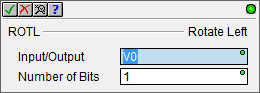
The instruction will have two parameters. Input/Output is the area in which the bit movement will take place. The number of bits will indicate the amount of movement that will happen. In our case, the bits in V0 will move 1 bit left. Left indicates the movement will happen from bit 00 to bit 15 of V0.
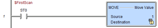
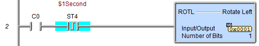
In our example, we move a one into memory address V0 at the first scan bit of the PLC. When C0 is on, we enable the one-second system pulse on the leading edge to trigger our rotate left instruction. When bit 15 is rotated this then appears at bit 00.
ROTR – Rotate Right – BRX Do-More Shifting Instructions
The Rotate Right (ROTR) instruction rotates the bits in the specified location a specified number of bit locations to the right. Bits that are rotated out on the right are rotated back in on the left.
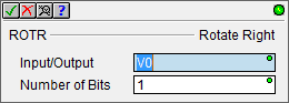
This instruction has the same inputs as the rotate left instruction.
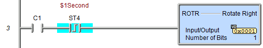
When C1 is on, we enable the one-second system pulse on the leading edge to trigger our rotate right instruction. When bit 00 is rotated this then appears at bit 15. If both C0 and C1 are on the bit status in V0 is unchanged. (The rotate right will cancel out the rotate left, leaving the V0 unchanged at the end of the scan.)
Math Shift Left Operator – BRX Do-More Shifting Instruction
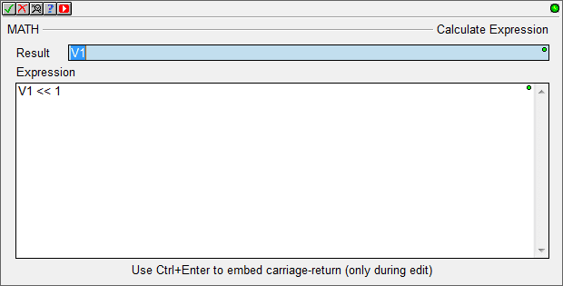
The Math Shift Left operator ( << ) causes the bits in left operand to be shifted to the left by the number of positions specified by the right operand. A left shift is a logical shift which means that the bits that are shifted off the end are discarded, including the sign bit. The bit positions that have been vacated by the left shift operation are zero-filled.
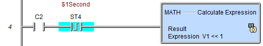
In our example, when C2 is on, we enable the one-second system pulse on the leading edge to trigger our math instruction. Bits in V1 are shifted to the left by 1. (V1<<1)
Math Shift Right Operator – BRX Do-More Shifting Instruction
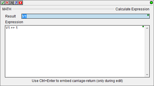
The Math Shift Right operator ( >> ) causes the bits in left operand to be shifted to the right by the number of positions specified by the right operand. A Right Shift is a logical shift which means that the bits that are shifted off the end are discarded. The bit positions that have been vacated by the Right Shift operation are filled with the sign bit. The following post will explain the meaning of the signed registers.
WHAT EVERYBODY OUGHT TO KNOW ABOUT PLC (PROGRAMMABLE LOGIC CONTROLLER) NUMBERING SYSTEMS
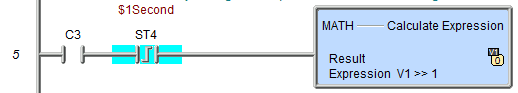
When C3 is on, we enable the one-second system pulse on the leading edge to trigger our math instruction. Bits in V1 are shifted to the right by 1. (V1>>1) Note: If Bit 15 is on then a 1 is shifted always to the right.
Math Unsigned Shift Right Operator – BRX Do-More Shifting Instruction
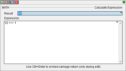
The Math Shift Right operator ( >>> ) causes the bits in left operand to be shifted to the right by the number of positions specified by the right operand. An Unsigned Right Shift is a logical shift which means that the bits that are shifted off the end are discarded. The bit positions that have been vacated by the Unsigned Right Shift operation are zero-filled.
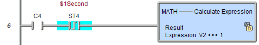
When C4 is on, we enable the one-second system pulse on the leading edge to trigger our math instruction. Bits in V1 are shifted to the right by 1. (V1>>>1) Note: If Bit 15 is on then a 0 is shifted always to the right. (unsigned)
SR – Shift Register – BRX Do-More Shifting Instructions
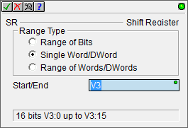
The Shift Register (SR) instruction shifts BITs through a predefined number of BIT locations. These BIT locations can be a range of BITs, a single Word or DWord, or a range of Words or DWords.
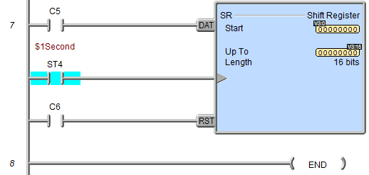
In our example, we have C5 as the input to the shift register. This will determine if a 1 or 0 will be placed in the first bit of the range or word. The one-second system clock bit flag is used as the clock input. This is triggered on the positive edge (one-shot) and will shift the information from bit 0 of the range or word to the left by one. C6 will reset our shift register.
We have covered shift registers in the following previous posts:
https://accautomation.ca/plc-programming-example-shift-register-conveyor-reject/
https://accautomation.ca/plc-programming-example-sorting-station-shift-register
You can watch the video below to see how the shift instructions work in the BRX Do-More Series PLC.
You can download the program here.
BRX Do-More Series PLC from Automation Direct – Power to deliver
Overview Link (Configure and purchase a system)
Manuals and Product Inserts (Installation and Setup Instruction)
Do-More Designer Software v2.0.3 (Free Download Link) – The software will contain all of the instruction sets and help files for the BRX Do-More Series PLC.
Next time we will look at the drum instruction in the BRX Do-More PLC.
Watch on YouTube: BRX Do-More PLC Shifting Instructions
If you have any questions or need further information please contact me.
Thank you,
Garry
If you’re like most of my readers, you’re committed to learning about technology. Numbering systems used in PLC’s are not difficult to learn and understand. We will walk through the numbering systems used in PLCs. This includes Bits, Decimal, Hexadecimal, ASCII, and Floating Point.
To get this free article, subscribe to my free email newsletter.
Use the information to inform other people how numbering systems work. Sign up now.

The ‘Robust Data Logging for Free’ eBook is also available as a free download. The link is included when you subscribe to ACC Automation.