PLC programming is a valuable skill that can be learned without a significant financial investment. With the EasyPLC learning suite, you can gain hands-on experience with industrial simulation and connect it to PLCs. One such PLC option is the free simulator of the Do-More Designer, which provides a practical platform for learning.
We will guide you through the five steps of PLC program development, focusing on programming the do-more simulator to communicate with the EasyPLC Box Dumper. By following these steps, you will gain a solid understanding of PLC programming and be able to apply your knowledge to real-world scenarios.
The first step in this process is to define the task at hand. In this case, our task is to program the do-more simulator to control the Box Dumper. This involves understanding the functionality of the Box Dumper and determining how the PLC can be programmed to interact with it effectively.
By breaking down the learning process into manageable steps, we aim to make PLC programming accessible and understandable for beginners. So, let’s dive in and start our journey toward mastering PLC programming with the EasyPLC learning suite and the do-more simulator.
Learn PLC programming the easy way. See below how to receive a 10% discount on this cost-effective learning tool. Invest in yourself today.
Previously, we have done the following:
Easy PLC Installing the Software – Video
EasyPLC Software Suite – Quick Start – Video
Click PLC – Easy Transfer Line Programming – Video
Productivity PLC Simulator – Chain Conveyor MS – Video
Do-More PLC – EasyPLC Box Selection Program – Video
Click PLC EasyPLC Gantry Simulator – Video
Click PLC Simple Conveyor EasyPLC – Video
EasyPLC Paint Line Bit Shift – BRX Do-More PLC – Video
Click PLC – EasyPLC PLC Mixer Programming – Video
Click PLC EasyPLC Warehouse Stacker Example – Video
– Operation Video
EasyPLC Machine Simulator Productivity PLC Robotic Cell – Video
EasyPLC Simulator Robotic Cell Click PLC – Video
Palletizing Conveyor Programming Do-More PLC – Video
Palletizing Conveyor Programming – Click PLC – Video
Product Quality Verification! Do-More PLC Sequencer – Video
Revolutionize Learning PLCs with Pallet 3D Sim! – Video
Robot Packing PLC Program Development – Video
Define the task: (Step 1 – Box Dumper PLC Learning)
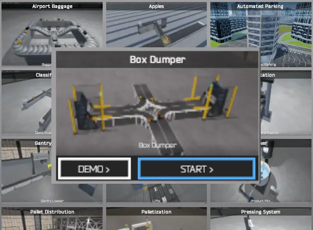
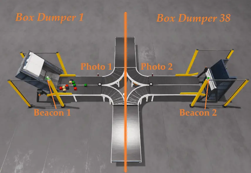
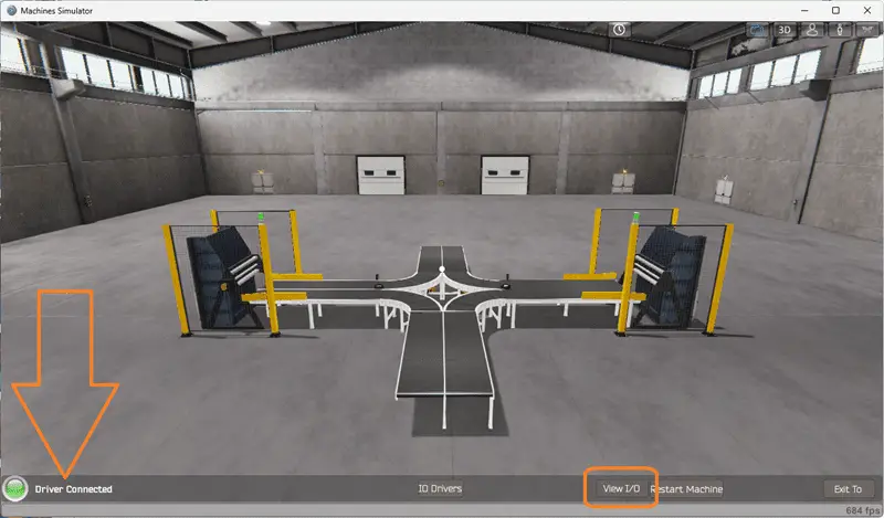
To define the task for programming the Box Dumper PLC, the first step is to understand what needs to be done. This involves launching the EasyPLC Machine Simulator (MS) and accessing the machine’s menu. Select the “Box Dumper” option from there, serving as our programming example. On the left side of the screen, you will find information on how the robot packing machine should function.
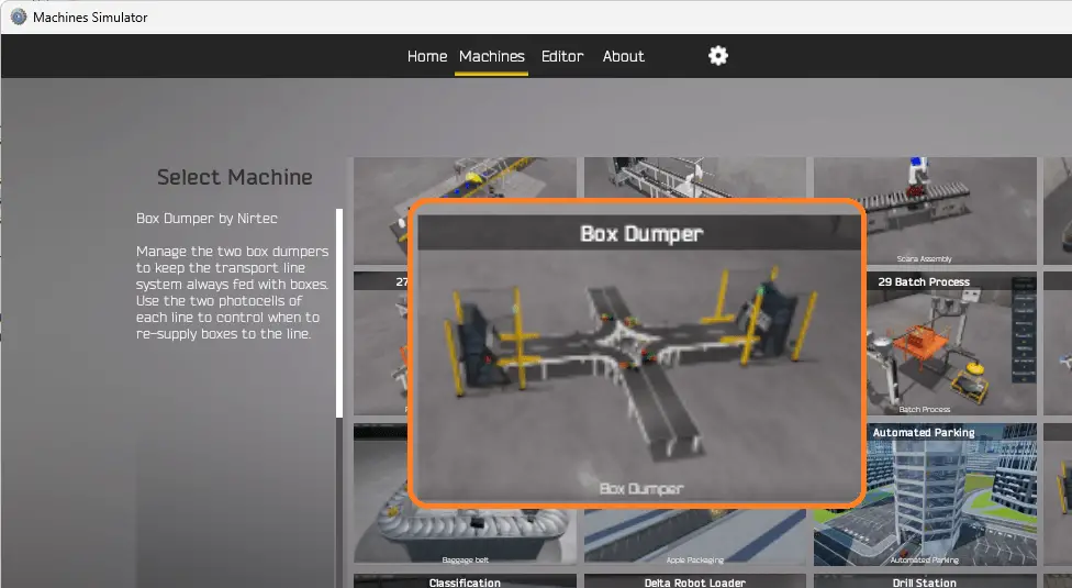
This task aims to manage the two box dumpers to ensure a continuous supply of boxes to the transport line system. This is achieved by using the two photocells on each line to control when boxes need replenishment. By understanding the functionality of the box dumper and how it interacts with the transport line system, you can effectively program the PLC to control its operation.
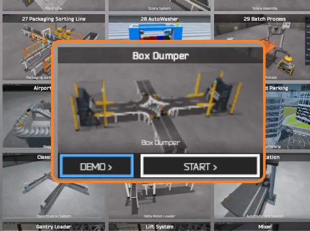
To familiarize yourself with the operation of the box dumper, you can utilize the built-in demo mode. This demonstration mode provides a visual demonstration of how the box dumper functions.
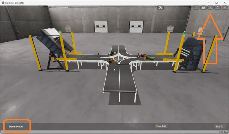
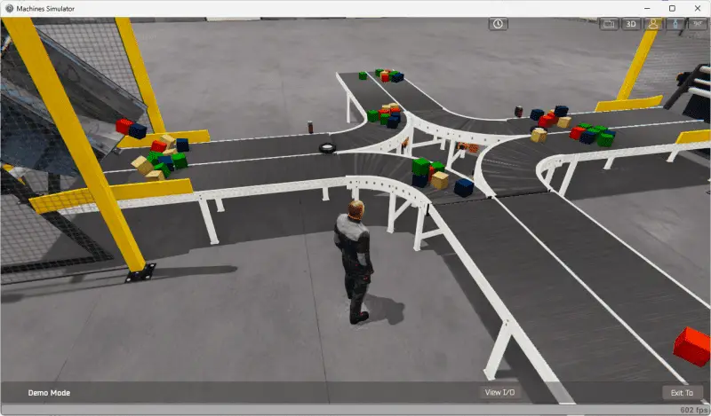
Take some time to explore the 3D virtual environment using the navigation icons at the top of the window. The default selection allows you to move freely without colliding with any components, while the first-person and third-person modes provide different perspectives.
By exploring the demo mode, you can better understand how the box dumper operates and how it fits into the overall system. This will help you develop the PLC program to control the box dumper’s actions effectively.
Once you have a clear understanding of the task at hand and have familiarized yourself with the box dumper’s operation, you can proceed to the next step in developing the Do-More PLC program. By following these steps and gaining hands-on experience with the EasyPLC learning suite and the do-more simulator, you will be well on your way to mastering PLC programming and applying your knowledge to real-world scenarios. So, let’s continue our journey and move on to the next step in the process.
Define the Inputs and Outputs: (Step 2 – Box Dumper PLC Learning)
Defining the inputs and outputs is crucial to effectively programming the Box Dumper PLC. Inputs are signals or data received by the PLC, while outputs are signals or data sent by the PLC to control external devices. By understanding the inputs and outputs, you can develop a program that reads the status of the inputs and activates the appropriate outputs.
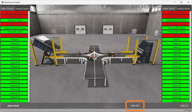
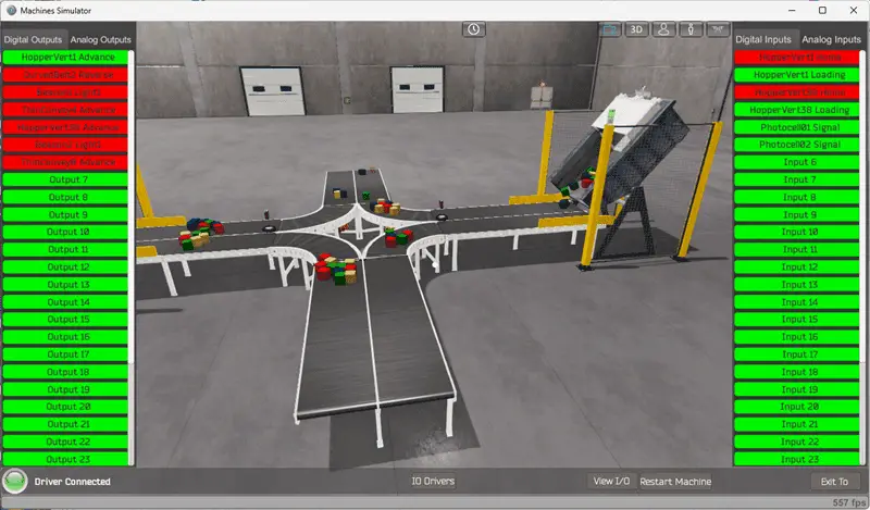
While still in demo mode, select View IO to display the inputs and outputs required for this machine. This PLC programming example will require seven outputs and six inputs.
In the case of the Box Dumper PLC case, the inputs include the status of the photocells on each line, indicating whether boxes need replenishment. These inputs will be used to determine when the box dumper should be activated. The outputs include signals to control the box dumper’s motor, conveyor belts, and other components.
If you are unsure what output or input is doing, start the Box Dumper machine in Start mode. Select the View IO on the bottom middle of the auto packer machine simulator window.
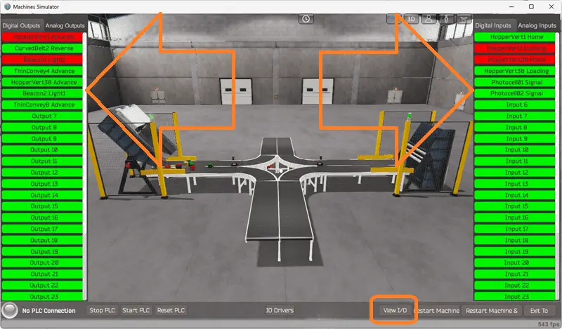
You can manually run the robot packer without any control or PLC connection. Select the outputs on the left to turn on, and monitor the inputs on the right.
Defining the inputs and outputs establishes the communication between the PLC and the external devices. This allows the PLC program to monitor the inputs and continuously decide based on their status. The program can then activate the appropriate outputs to control the box dumper’s operation.
The machine simulator will communicate with a do-more designer PLC simulator. Communication will be done with Modbus TCP (Ethernet).
The Do-More Series of PLCs uses a fixed Modbus memory area. This area can be seen in the following chart.
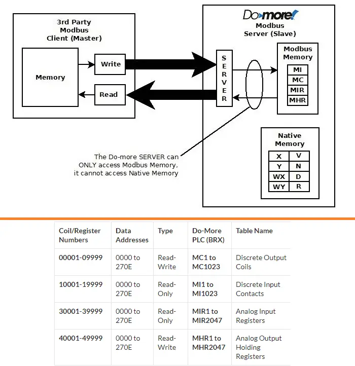
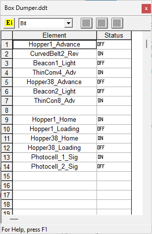
The following table will define the inputs and outputs (IO) and Modbus addresses in the Do-More PLC we will use for this program. (EasyPLC Easy Transfer Line)
| Digital Type | Description | Do-More PLC Modbus Address | Machine Simulator Modbus Address |
| PLC Output – MS Input | Hopper1 Advance | MI1 – 10001 | 0 |
| PLC Output – MS Input | CurvedBelt2 Reverse | MI2 – 10002 | 1 |
| PLC Output – MS Input | Beacon1 Light | MI3 – 10003 | 2 |
| PLC Output – MS Input | ThinConvey4 Advance | MI4 – 10004 | 3 |
| PLC Output – MS Input | Hopper38 Advance | MI5 – 10005 | 4 |
| PLC Output – MS Input | Beacon2 Light | MI6 – 10006 | 5 |
| PLC Output – MS Input | ThinConvey8 Advance | MI7 – 10007 | 6 |
| PLC Input – MS Output | Hopper1 Home | MC1 – 1 | 0 |
| PLC Input – MS Output | Hopper1 Loading | MC2 – 2 | 1 |
| PLC Input – MS Output | Hopper38 Home | MC3 – 3 | 2 |
| PLC Input – MS Output | Hopper38 Loading | MC4 – 4 | 3 |
| PLC Input – MS Output | Photocell1 Signal | MC5 – 5 | 4 |
| PLC Input – MS Output | Photocell2 Signal | MC6 – 6 | 5 |
Note: The machine simulator will be offset by one on the Modbus Addresses. See the video below for the demo mode and determining inputs and outputs.
It is important to note that PLC programs operate cyclically, meaning they continuously read the inputs and set the outputs. This ensures that the program is responsive to changes in the system and can adapt accordingly. By understanding the inputs and outputs and their relationship to the overall system, you can develop a logical sequence of operation for the Box Dumper PLC program.
Develop a logical sequence of operation: (Step 3 – Box Dumper PLC Learning)
Developing a logical sequence of operations is crucial in programming the Box Dumper PLC. To ensure a smooth and efficient operation, it is important to create a flow chart, sequence table, or detailed information that thoroughly outlines the process that needs to be controlled. This will help answer important questions such as what happens during a power or pneumatic air loss, or if any input/output devices fail. Additionally, it is essential to determine if redundancy is necessary.
By understanding all aspects of the operation upfront, you can save yourself a lot of work and prevent the need to continuously rewrite the PLC program logic. As a PLC programmer, it is vital to have a comprehensive understanding of the sequence and operation of the machine before starting the programming process. This can be achieved by asking questions or reviewing existing documentation to ensure a clear understanding of the logical steps involved.
Our system has three outputs that control all of the conveyors. When the system is running, all of the conveyors will be turned on. We have two Box Dumpers. These will alternate with each other so that they are never on simultaneously. An internal bit will be used to alternate between the Box Dumpers. When the first scan bit of the PLC turns on, the bit is set. It is also set by a hopper advancing and in the loading position. The Reset of the bit will happen when the other hopper advances and is in the loading position.
The operation of each of the Box Dumpers will be the same. When we see the internal alternative signal, the hopper is in the home position, the photocell does not see a box, and the previous box dump has reached the sensor. Then, we set the hopper advance and the box dump reach bit. When the hopper is in the loading position, it resets its advanced signal. The box dump reach bit is a quick indication that the boxes have moved after the previous dump. This bit will reset when the photocell sees a box or during the first scan of the PLC.
The beacon light on each of the Box Dumpers will flash at 1-second intervals when the hopper is not in the home position or the hopper advanced is on.
By developing a logical sequence of operation, you can create a PLC program that effectively controls the Box Dumper and ensures its smooth and reliable functioning. This step sets the foundation for the subsequent development of the Do-More PLC program, which will be covered in the next section.
Develop the Do-More PLC program: (Step 4 – Box Dumper PLC Learning)
Developing the Do-More PLC program is the next step in learning how to program the Box Dumper. This step involves taking the logical sequence of operation that was developed in the previous section and translating it into a program that the PLC can execute.
To begin, it is important to understand the programming language used by the PLC. The Do-More PLC uses ladder logic, which is a graphical programming language that represents the control logic in a series of rungs. Each rung comprises of inputs, outputs, and logic functions that determine the system’s behavior.
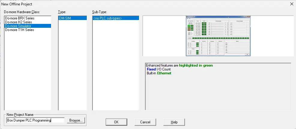
You can start building the ladder logic program by using the logical sequence of operations as a guide. Start the free Do-More Designer software. Select the new icon on the main page to start a new project. We will name this project and select OK.
Select documentation editor from the main menu | tools. We will map the inputs and outputs of the Box Dumper to the corresponding addresses in the PLC.
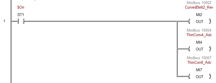
The first rung will turn on all of the conveyors with the internal system ON bit. This means the logic will be scanning as long as the PLC is in run mode, and these outputs will be active or on.
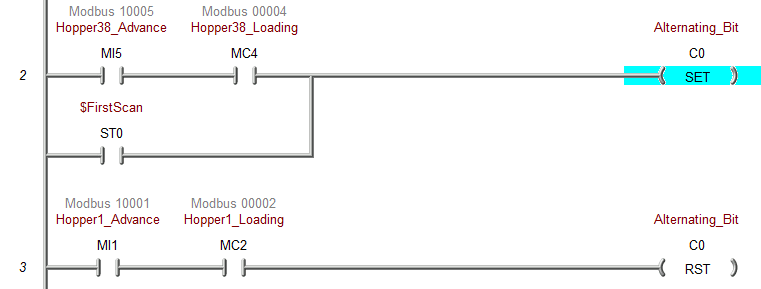
Rung 2 will set the alternating internal bit. This will select which box dumper to activate later in the program. If hopper 38 has been told to advance or dump, and it is not in the loading position, then set the alternating bit. This will also be set with the first scan bit flag. The Reset of this bit will be done when hopper one has been told to advance or dump, and is not in the loading position. When the alternating bit is on, hopper one will dump, and Hopper 38 will dump when off.
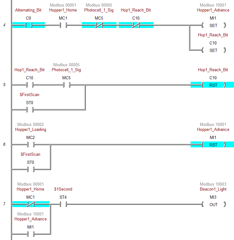
Rung 4 will set hopper one advance and the reach bit when hopper 1 is home, and we do not have photocell one or the hopper reach bit. This is all triggered when we have the alternating bit. The reach bit will reset when it is on, and we have photocell one or the first scan flag. The hopper one advance reset will happen when hopper one is loading, or the first scan bit is on. The beacon light will flash using the 1-second pulse bit flag, and the hopper one is advanced or not home.
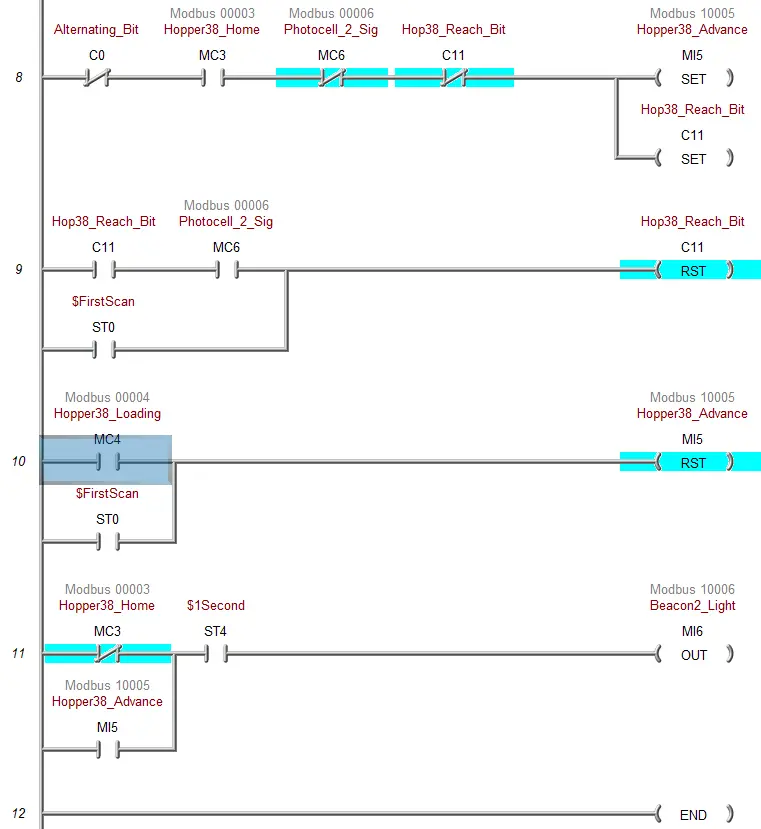
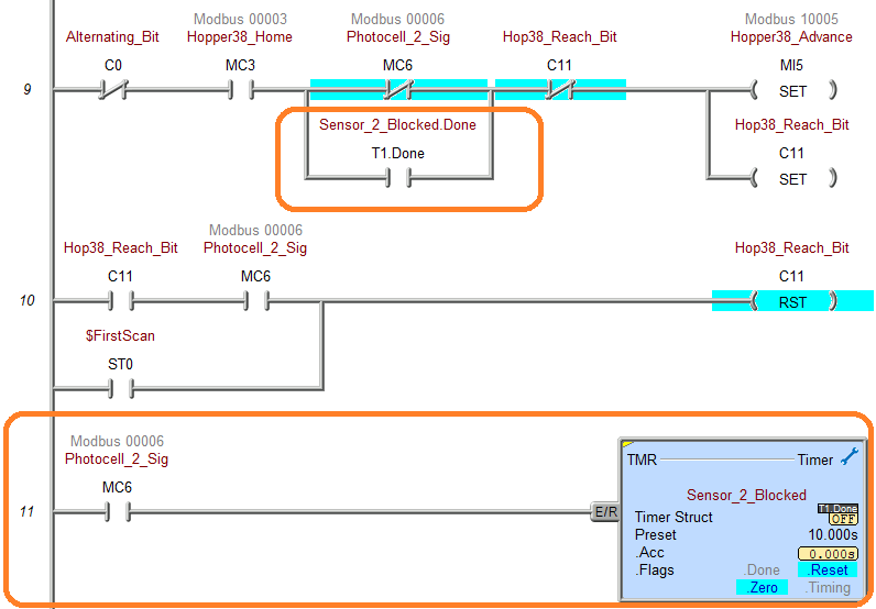
Rung 8 will start with the control for Hopper 38. It will be the same logic as Hopper 1 except with the corresponding signals. Beacon 2 will be used for Hopper 38.
This is the end of our ladder logic for the Box Dumper. An END statement will indicate that this is where the program ends and to repeat the scan. Save your program. It is important always to save your program during programming.
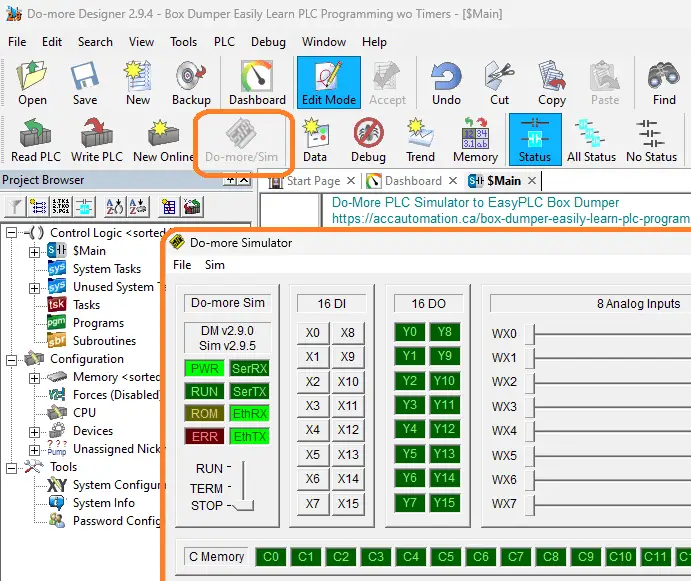
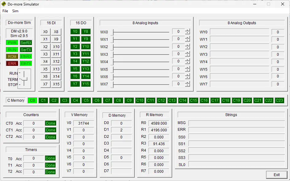
Select the Do-more/Sim icon. This will start the PLC simulator. The Do-More Designer simulator will run independently of the Do-More Designer programming software. When returning to the Do-More designer software, you will see we are connected to the simulator by the menu icons and the status bar at the bottom of the window.
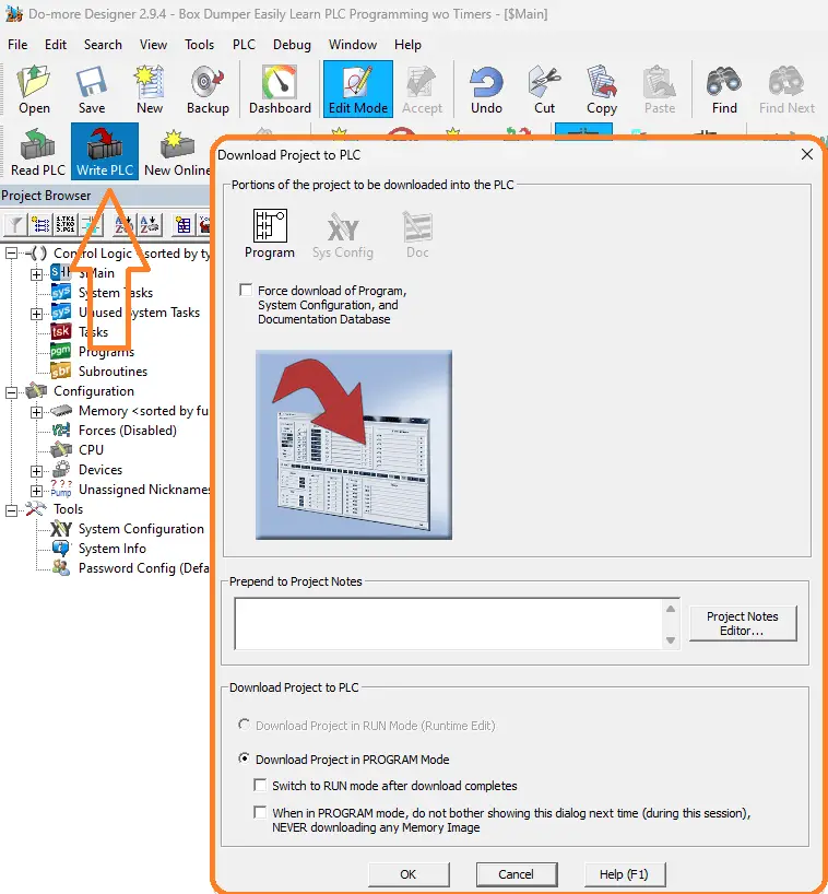
Select the Write PLC icon. This will transfer our program to the PLC simulator.
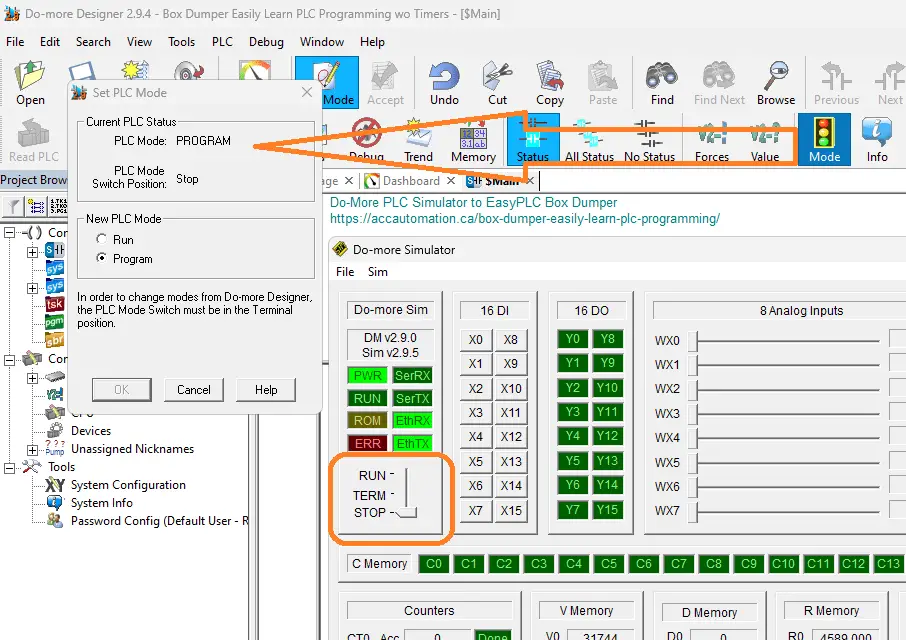
The Mode icon on the main menu will allow you to change the PLC mode from program to run. It also shows the PLC switch position. Select the run mode for the PLC. The Do-more PLC simulator will have a switch position that can also change to control the mode of the PLC.
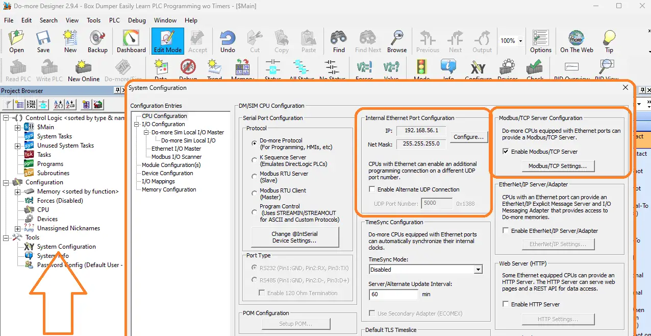
Select System Configuration under the tools menu of the project browser. This will display the System Configuration window. Under Internal Ethernet Port Configuration, you will see the IP address for the PLC simulator. Besides this selection, there is also the Modbus/TCP Server Configuration. Ensure that this is enabled. This PLC simulator will act as a Modbus TCP Server to the EasyPLC Modbus TCP Client. A Modbus client will send requests, and the Modbus server will respond. Make a note of the IP address. We will need this to set up our Modbus Client in the next step.
Watch the video below to see this being programmed in ladder logic.
By following a systematic approach and referring to the logical sequence of operation, you can develop a robust and efficient Do-More PLC program for the Box Dumper. This program will serve as the machine’s brain, controlling its movements and ensuring its safe and reliable operation.
Test the PLC program: (Step 5 – Box Dumper PLC Learning)
To ensure the functionality and accuracy of the Do-More PLC program for the Box Dumper, it is essential to test the program thoroughly. Utilizing a Machine Simulator (MS) is an effective way to do this. Using the MS, you can simulate the operation of the Box Dumper without needing physical hardware, minimizing the risk of damage during the testing phase.
We will use Modbus TCP on our Do-More PLC simulator to communicate with the EasyPLC Machine Simulator. Call up the box dumper machine simulator in start mode.
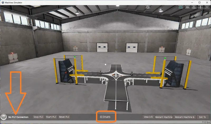
The status of the machine simulator will be at the bottom of the screen. Currently, we have no PLC connected. Select IO Drivers on the bottom middle of the screen.
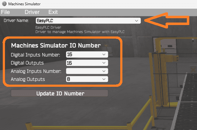
The machine simulator IO number will be displayed. Ensure we select more IO than the number required for our box dumping machine. The EasyPLC driver is selected by default.
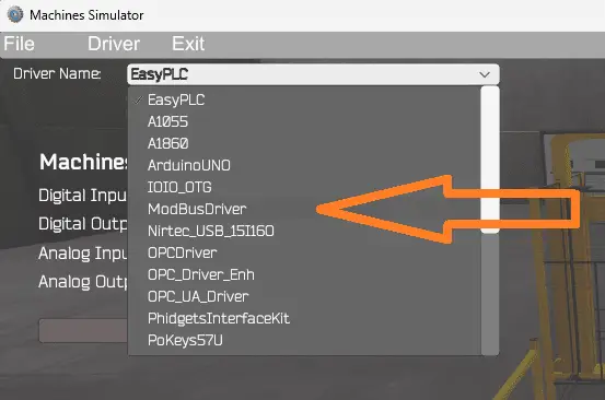
Under the driver pull-down menu, select “ModBusDriver.” This driver will communicate Modbus TCP (Ethernet) and Modbus RTU (Serial).
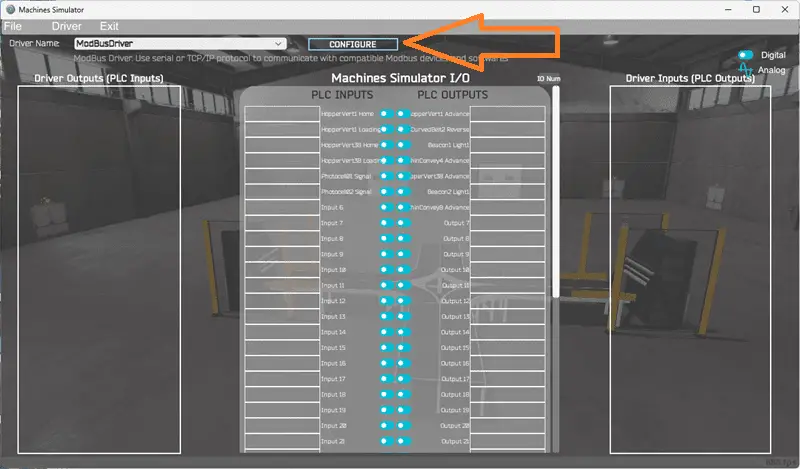
Select the configure button.
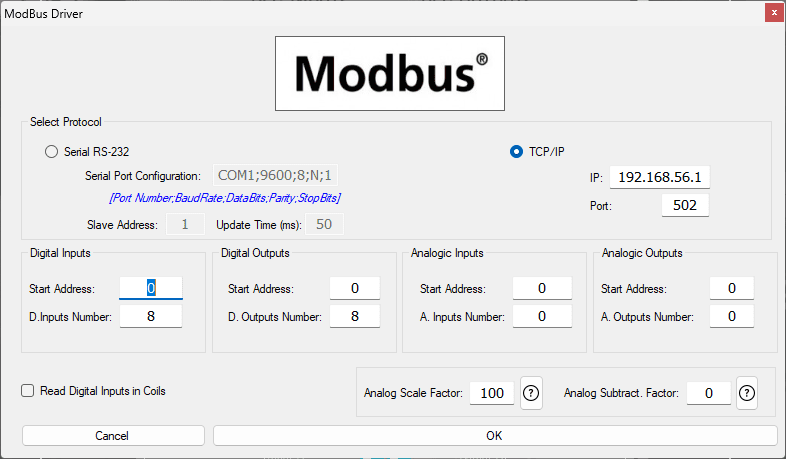
We can now enter the information for our Modbus driver. Select TCP/IP. This means the Ethernet port on the computer will communicate with the Do-more PLC simulator. The digital inputs from MS to the Do-More PLC will be MI1 to MI7. This will start at address 0 due to the offset of 1. Digital outputs from MS to the Do-More PLC will be MC1 to MC6. This will begin at address 0 due to the offset of 1. Select the OK button.
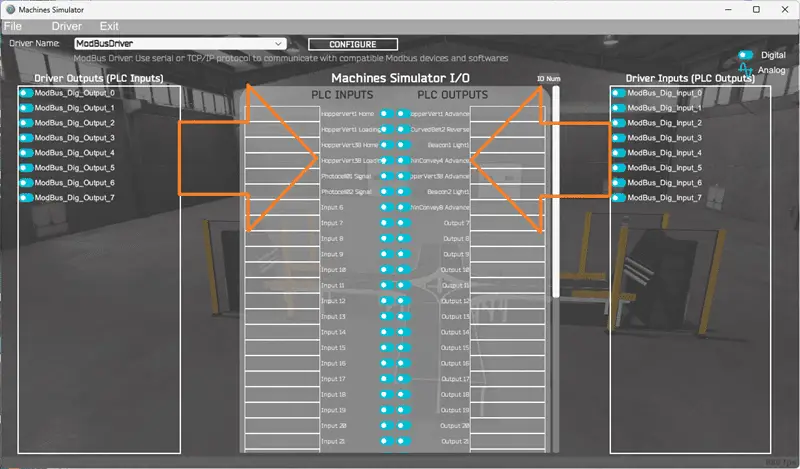
You will now see the inputs and outputs specified for the Modbus driver. We can now manually assign the driver outputs to the PLC inputs and driver inputs to the PLC outputs. However, the automatic assignment works well and will save you time.
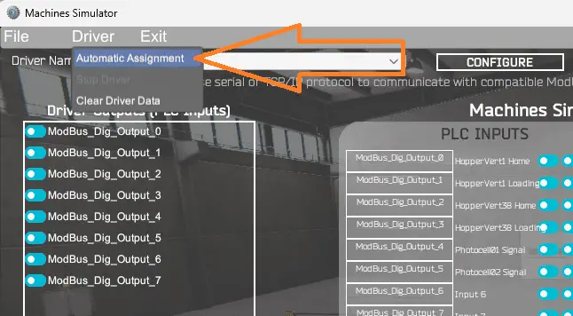
Select Automatic Assignment from the driver option in the main menu.
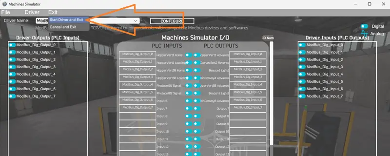
This will automatically assign the PLC simulator IO to the Machine Simulator IO. Select Start Driver and exit from the main menu.
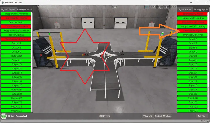
On the bottom left side of the window, the driver communicates to the Do-More PLC simulator with the green light. Select view IO to know the input and output status of the machine simulator.
Ensure that the Do-More PLC is in run mode. We can see the operation of our box dumping machine. The digital inputs and outputs of the MS will correspond to the PLC controller.
Using the Data View window of the Do-More Designer programming software, we can also watch the inputs and output operations.
Using Machine Simulator (MS) to test the program will ensure that our program works. Troubleshooting is quickly done without damage to any physical hardware.
While the box dumper runs for some time, you will notice that the boxes can get stuck in front of the photocells. When this happens, the box dumper cycling stops.
We can correct this by adding timers for the photocells. If the photocell is on for more than 10 seconds, bypass the photocell and have the box dump another load. This will then dislodge the boxes in front of the photocells.
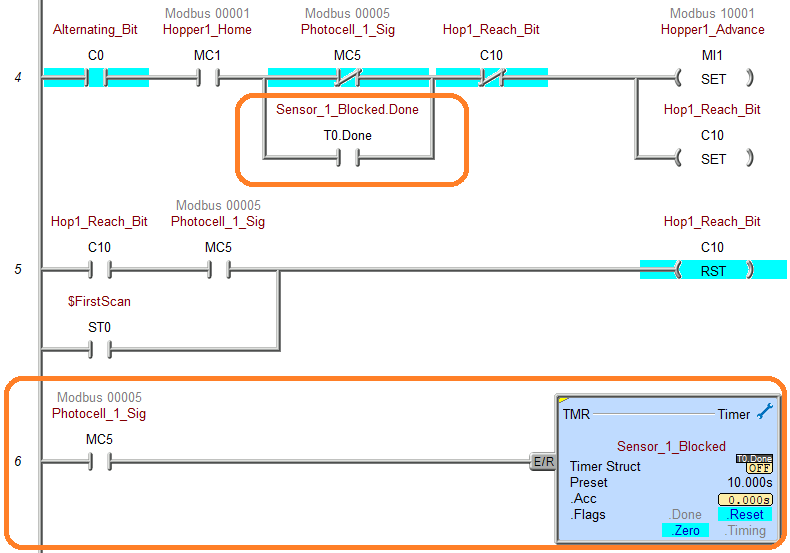
We will use online editing of the Do-More PLC software to add the timers for each photocell.
By utilizing the MS to test the Do-More PLC program for the Box Dumper, you can confidently verify its functionality and address any potential issues before implementing it on the actual machine.
This testing phase is crucial in ensuring the safe and reliable operation of the Box Dumper, providing peace of mind and minimizing downtime.
You can practice your modification and debug by modifying the robot packing operation in the following way:
– Add a control panel with start and stop pushbuttons.
– Add jog buttons to the control panel to cycle the box dumpers.
– Calculate the rate of box dumps for this machine in dumps per hour.
Let me know how you make out in the comments below.
Download the PLC sample program here.
Watch the video below to see the five steps of program development applied to the robot packing machine. The machine simulator is one of the best applications to help you learn PLC programming.
EasyPLC Software Suite is a complete PLC, HMI, and Machine Simulator Software package. This PLC learning package includes the following:
Easy PLC – PLC Simulation allows programming in Ladder, Grafcet, Logic Blocks, or Script.
HMI System – Easily create a visual human-machine interface (HMI)
Machine Simulator – A virtual 3D world with real-time graphics and physical properties. PLC programs can be tested using EasyPLC or through other interfaces. (Modbus RTU, TCP, etc.)
Machine Simulator Lite – Designed to run on Android Devices.
Machine Simulator VR – Virtual Reality comes to life so you can test, train, or practice your PLC programming.
Purchase your copy of this learning package for less than USD 95 for a single computer install or less than USD 110 to allow different computers.
Receive 10% off the price by typing in ACC in the comment section when you order. http://www.nirtec.com/index.php/purchase-price/
Learn PLC programming the easy way. Invest in yourself today.
Watch on YouTube: Box Dumper Easily Learn PLC Programming
If you have any questions or need further information, don’t hesitate to contact me.
Thank you,
Garry
If you’re like most of my readers, you’re committed to learning about technology. Numbering systems used in PLCs are not challenging to learn and understand. We will walk through the numbering systems used in PLCs. This includes Bits, Decimals, Hexadecimal, ASCII, and Floating Points.
To get this free article, subscribe to my free email newsletter.
Use the information to inform other people how numbering systems work. Sign up now.

The ‘Robust Data Logging for Free’ eBook is also available for free download. The link is included when you subscribe to ACC Automation.