The C-More HMI Panel software uses virtual components called Objects. These objects are programmable to simulate the functions that you require on your automation project. Pushbuttons, Switches, meters, and graphs are just a few of the objects that are available to you.
The Alarm List Objects include a variety of options to customize the display of alarms as a screen. This is in addition to the alarm banner at the bottom of the screen that shows the active alarms. We also have the Alarm Screen Style setting in Panel Manager.
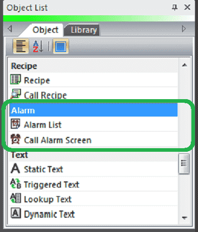
We will now look at the object list alarms that we can use with our HMI panel. The alarm objects that are available on the C-More EA9 are Alarm List and Call Alarm Screen. Alarms are specified as an event in the C-More HMI panel. We will program both discrete (On/Off) and limits on a range for our event alarms. Let’s get started.
Previously in this C-More EA9 HMI Panel series, we have done the following:
System Hardware
– Unboxing and Review Video
– Powering the Unit Video
Installing the Software – Video
System Setup Screens – Video
First Program
– Establishing Communication and Updating Firmware Video
– First Program Video
Panel to PLC and PLC to Panel Settings – Video
Common Screen Menu – Video
Simulate Project – Video
Object List Shapes – Video
Object List Buttons – Video
Object List Indicators – Video
Object List Entry – Video
Object List Meters and Graphs – Video
Object List Bitmaps – Video
Object List Recipe – Video
Define Custom Keypad – Video
Watch the video below to see the Object List Alarms in action on our C-More EA9 HMI Panel.
Setting Our Alarm Screens – C-More
We will be adding to the program we created last time. (C-More EA9 HMI Series Panel Define Custom Keypad).
Select a new screen under the main menu | Screen | New Screen…
Alternatively, we can also use the icons in the Navigation panel.
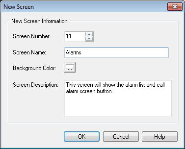
We will name screen 11 Alarms. The screen description can be used to describe the screen. Hit OK.
Our new screen will now be displayed.
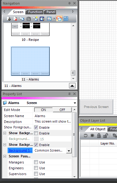
Under the property, list window turn on the editing and enable the show background. Select Common Screen Menu under the background screen. Turn off the edit mode under the property list.
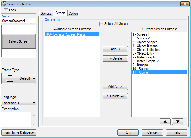
We must now add our new screen so we can select it when using the common screen menu. Select page 100. Select the Screen Selector button. Under the Screen tab, select page 11 – Alarms and hit the Add button so it moves it over to the Current Screen Buttons. Hit OK. We can now go back to our newly created Object Bitmap screen page 11 from our navigation window.
Our new screen is now ready for us to add our indicators.
Tag Name Database – C-More Alarms

We will use the following addresses to control the Alarms on our cmore HMI.
MC800 – Discrete On/Off – Modbus Address 00800 – Read / Write
MC801 – Discrete On/Off – Modbus Address 00801 – Read / Write
MHR800 – Unsigned Int 16 – Modbus Address 40700 – Read / Write
Alarm List – C-More
The alarm list will display event alarms on a page that we can specify. The information can be presented to the viewer in several different formats.
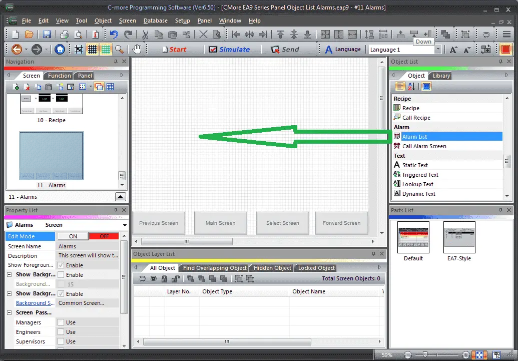
Select Screen 11 from the navigation window. We will now add an Alarm List under the Alarm heading in the Object list window. Left-click (hold) and drag the Alarm List onto the screen.
The Alarm List window will display. You can also use the main menu | Object | Alarm | Alarm List… and click on the work area of the screen. This will give you the default alarm list selection.
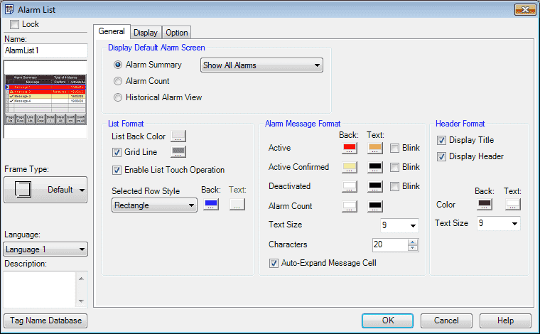
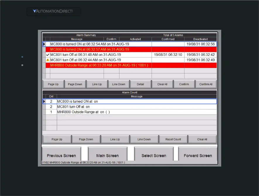
We will change the Alarm Message Format to the text size of 12. Our display default alarm screen will be Alarm Summary (Show All Alarms).
The alarm summary can have the following selections:
Show All Alarms (Default)
Show Active Alarms Only
Show Deactivated Alarms Only
Show Confirmed Alarms Only
Show Unconfirmed Alarms Only
All of the other parameters we will leave as their default. Select the Display tab.
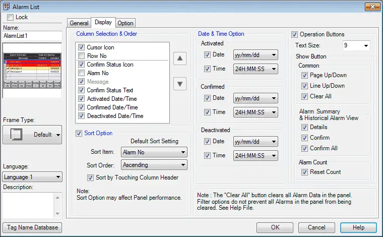
The display tab will allow us to change or modify the information viewed that we have selected for our alarm summary. We will leave all of these on their default settings. Select the Options tab.
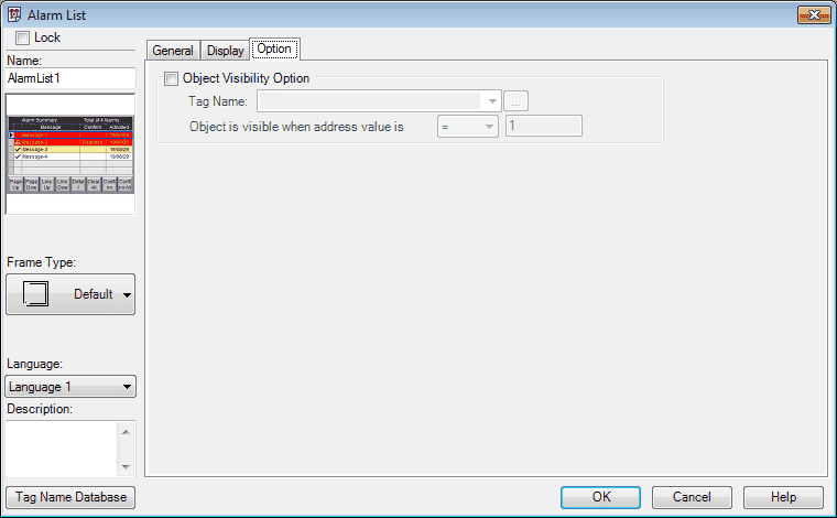
We can set the visibility of the alarm list. In our case, we will not set this parameter. Select OK.

We can now use the mouse to size and position our alarm list on the screen.
Select and drag the Alarm List again to the work area.
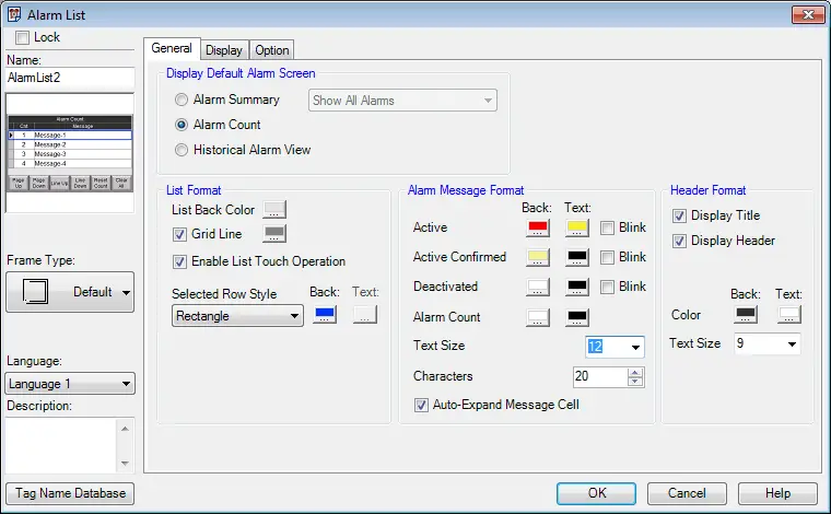
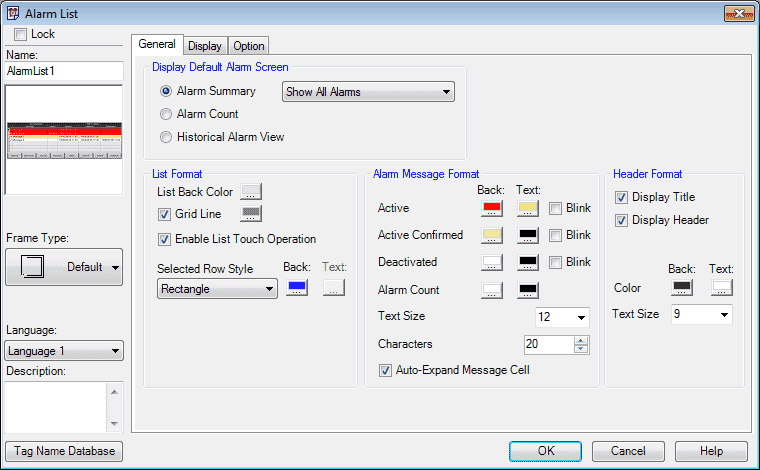
We will now select Alarm Count under the Display Default Alarm Summary. Change the alarm message format text size to 12. We will keep all of the other parameters, display tab and options tab as their default settings. Select OK.
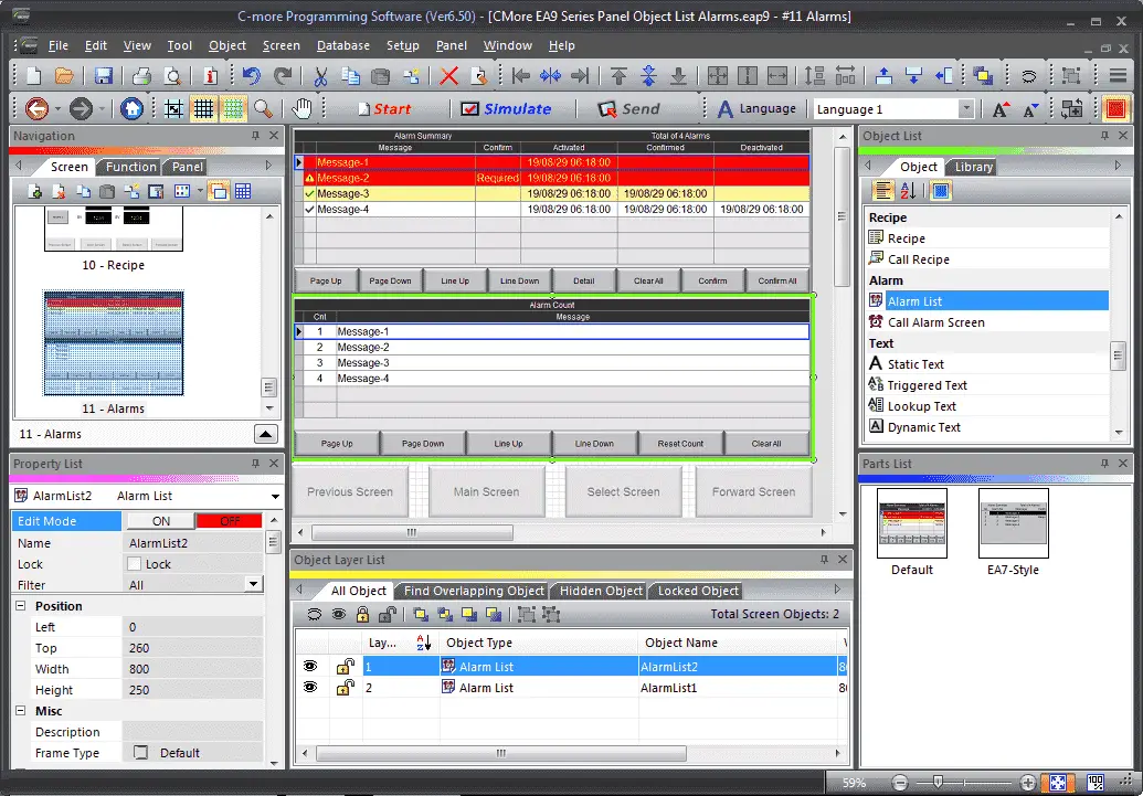
We can now use the mouse to size and position our alarm list on the screen. Our alarm screen 11 is now complete.
Create another alarm screen. (See above instructions)
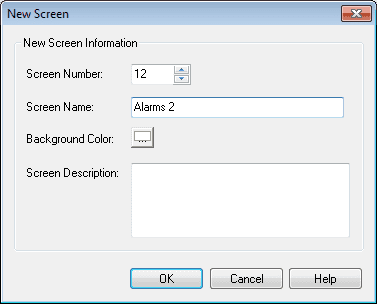
This will be Screen number 12 and be called Alarms 2. Remember to add our new screen so we can select it when using the common screen menu.
Select and drag the Alarm List to the work area on screen 12.
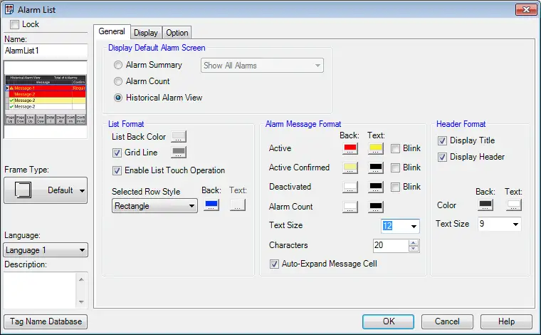
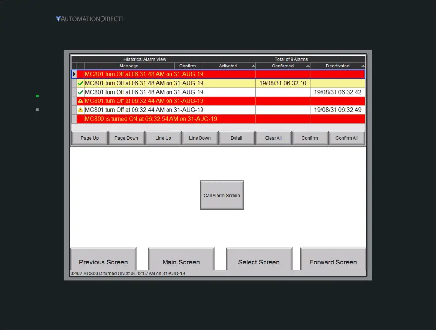
Select Historical Alarm View under the display default alarm screen in the General tab. We will also change our text size to 12 under the alarm message format. All other parameters on this general tab and other tabs will be left as their default. Select OK.
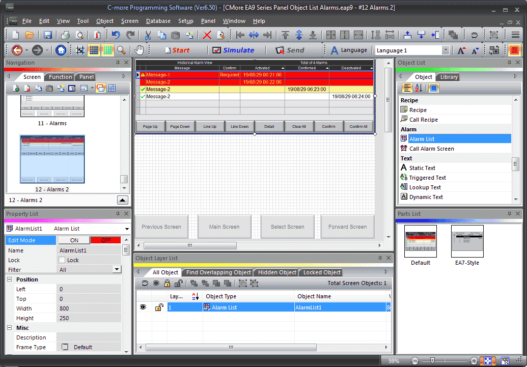
We can now use the mouse to size and position our alarm list on the screen. All three options for our Alarm List have now been programmed on our HMI display.
Call Alarm Screen – C-More
The call alarm screen (Button) will be used to display a system alarm screen. This will show the event alarms programmed.
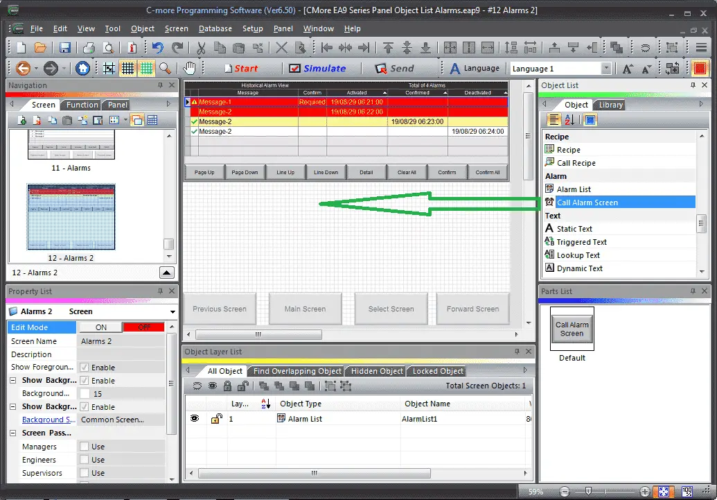
We will now add a Call Alarm Screen under the Alarm heading in the Object list window. Left-click (hold) and drag the Call Alarm Screen onto the screen.
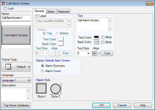
All of our settings for the general tab will be left as their default. You will see that we have the option of showing the Alarm Summary (default) or Alarm Count under the display default alarm screen on the general tab. Select the Options tab.
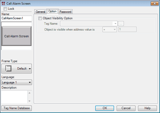
We will not use the visibility option in our example. Select the Password tab.
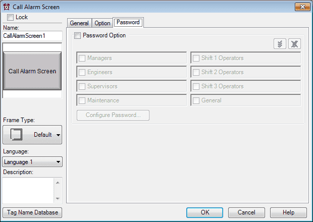
Password options can be used for this button that will be displayed on the HMI. We will not be using this option. Select OK.
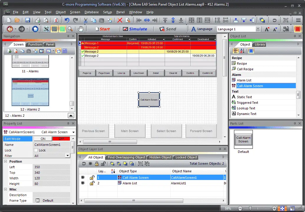
We can now use the mouse to size and position our call alarm screen button on the screen.
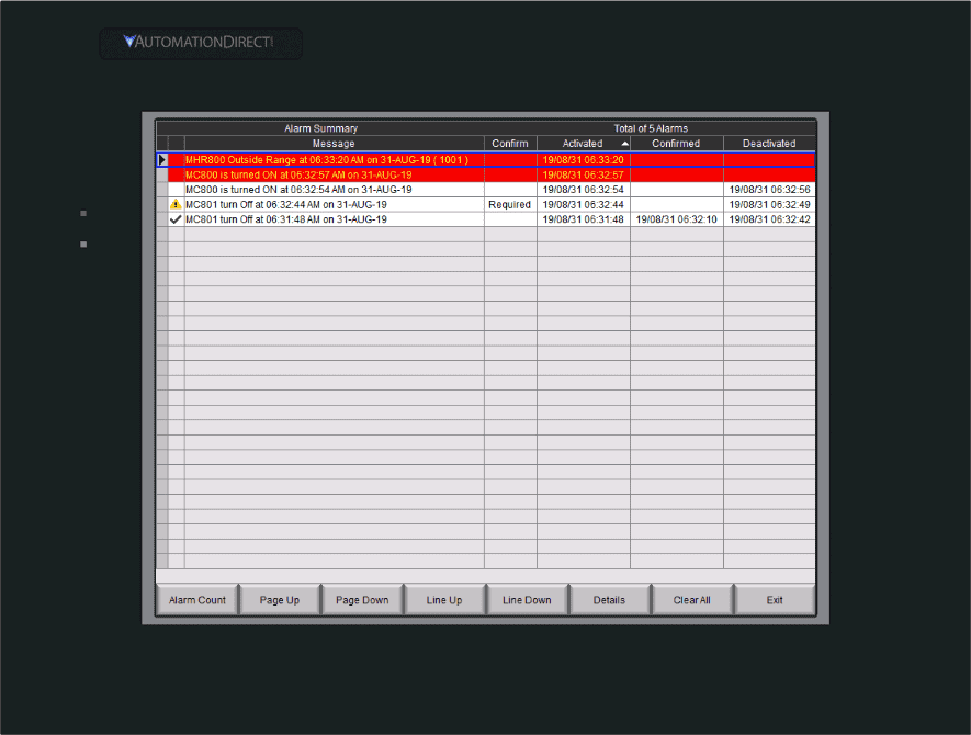
System Alarm Screen Format
When we use the Call Alarm Screen button this will bring up our system alarm screen. We can modify and view this in Panel Manager.
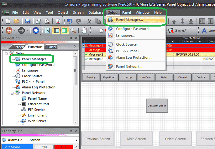
Select Panel Manager under the Setup in the Function tab of the Navigation window. Alternatively, you can use the main menu | Setup | Panel Manager…
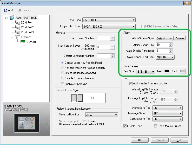
Under the Alarm settings, you can change the Screen Style, Queue Size, Display Time and Banner Text Size. We will leave these as their default values. Select Preview.
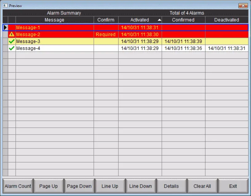
We can now see what our system alarm screen will now look like. Select the X in the top right corner to close the preview window. Select OK to close the panel manager window.
Our call alarm screen button is now programmed.
Event Manager Database (Alarm Database)
Alarms are configured in the Event Manager using an Alarm Action. It allows the user to configure other actions in conjunction with the Alarm such as popping up a Message Box, sending an email or even initiated a screen change. We will be discussing other actions as we move along in this C-More HMI series.
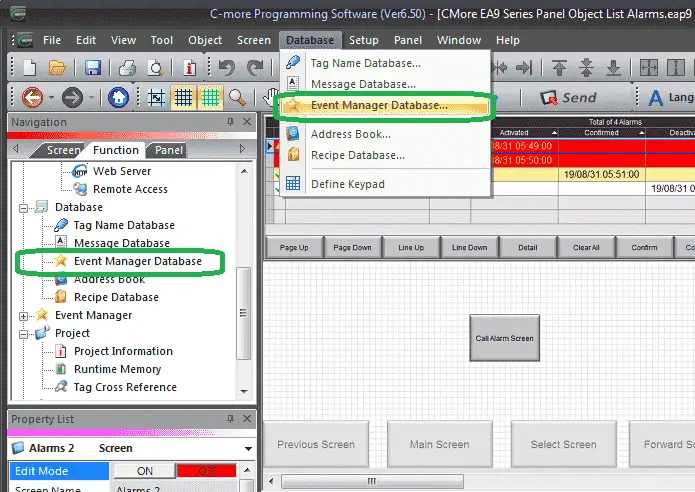
Select Event Manager Database from Database in the Function tab of the Navigation window. You can also use the main menu | Database | Event Manager Database…
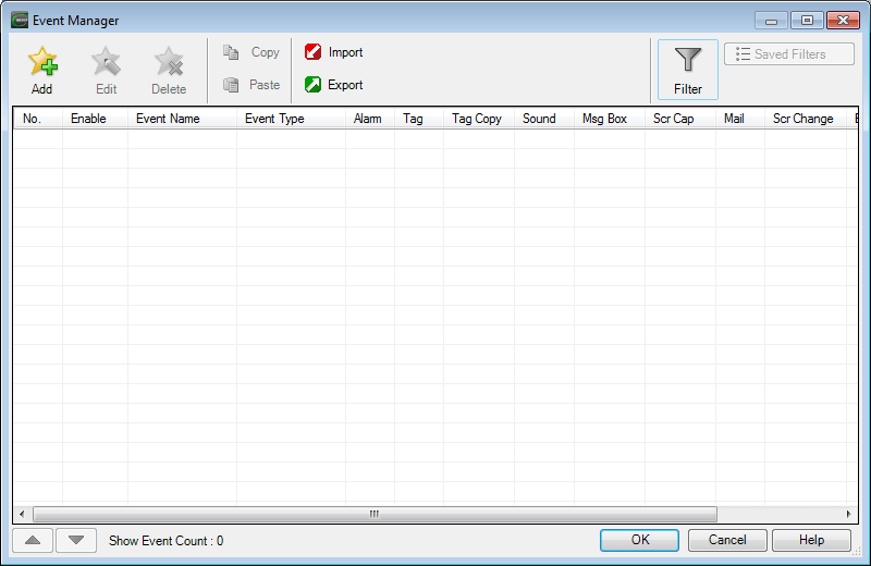
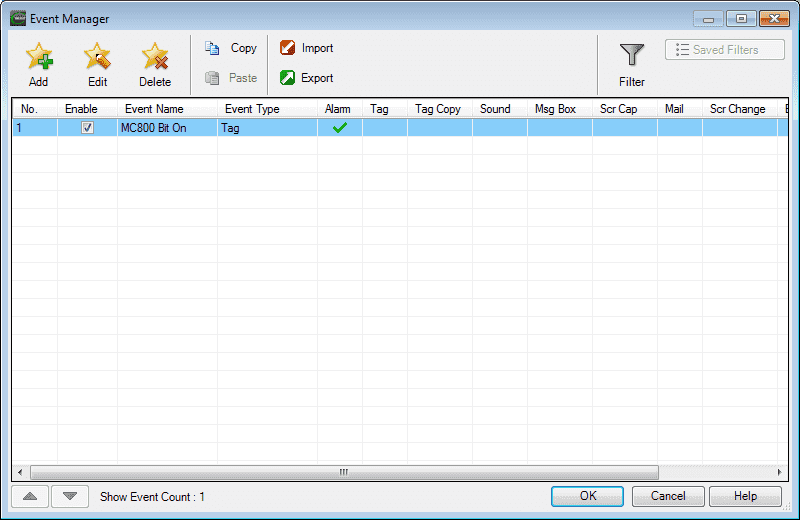
The event manager window will now be displayed. Select the Add icon.
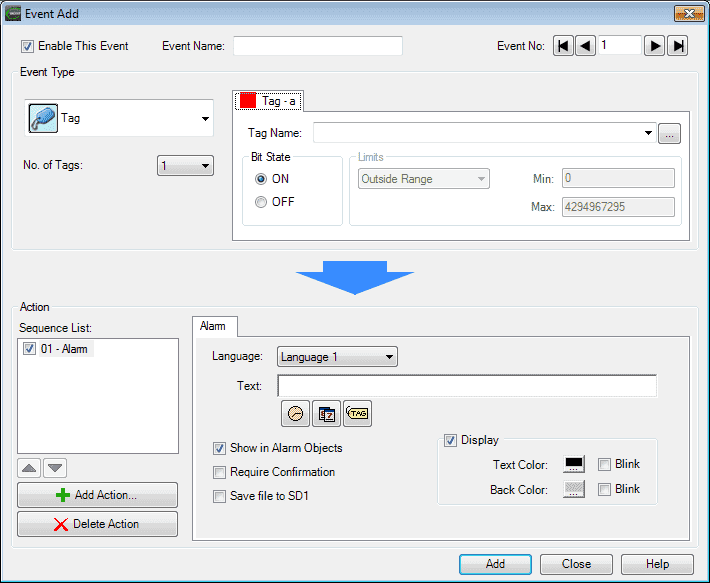
The event add window will now display. You will notice that under the Action heading 01 – Alarm is on by default.
Select the + Add Action…
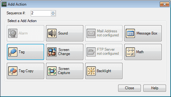
The add action window will not display. This will show you all of the different items that the event manager can use. Select Close to close the window.
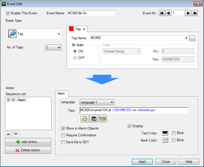
We will program in our first alarm event. Our example will have the following parameters:
Event Name – MC800 Bit On
Tag – a
Tag Name: – MC800 – This is selected from our tag database programmed above.
Bit State – ON – This means that the alarm will trigger when the bit turns on.
Alarm
Language: – Language 1
Text – MC800 is turned ON at <12H:MM: SS> on – The date and time are selected from the icons below for the text message to display.
Make sure the Show in Alarm Objects is selected. This will show on our display that we programmed above.
Display – This is selected to show at the bottom of the HMI screen. You can change the text and background colour if you want. We will leave this as the default.
Require Confirmation – Will have the operator confirm the alarm before it can be removed.
Save file to SD1 – This is a logging file that we can save events.
Select the Apply button on the bottom of the screen.
Our event will now show on our event manager window.

We will now add another event for MC801. The alarm will be triggered when the bit turns off. A confirmation is required for this alarm event. Select add to put this on our event manager table.
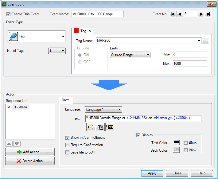
We will now add a tag that we want to look at a range. Select tag name MHR800. We will set the min value to 0 and the max value to 1000. The limits will be set to Outside Range. This means that if the value is less than 0 or greater than 1000 an alarm event will be triggered.
The alarm text will read: MHR800 Outside Range at <12H:MM: SS> on ( <####> ) – The part in the brackets afterward will be the embedded number from tag MHR800.
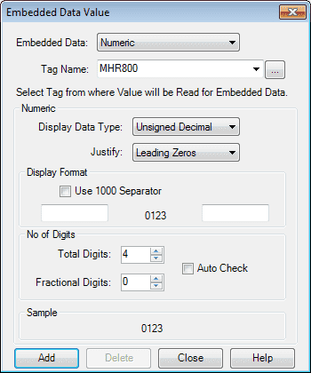
When you click on the embedded number icon, the embedded data value window will be displayed. You can change the information and the way the tag value is displayed on the alarm event text. Click Add when done.
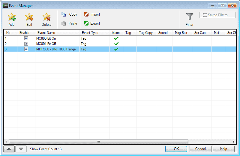
Here is our completed 3 events in our event manager window. Select OK to close the window.
C-More Alarms Simulation
We can simulate our HMI program to ensure that we have the screen look that we want.
Changing the bits in MC800 and MC801 will activate our alarms. MHR800 can also be set for values outside the range 0 to 1000 so an alarm event will occur.
Hitting the Call Alarm Screen button will all up the system alarm page.
See the video below to see the HMI in action with alarm selections.
C-More Alarms Program Additions
Using the program we previously developed, we will add additional rungs to the program for our Alarm Objects.
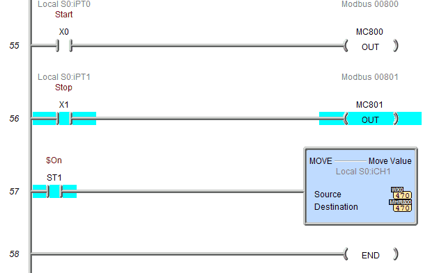
When X0 turns on this will turn on MC800 and activate an alarm. X1, when turned off, will activate an alarm with MC801. WX0 will control the number going into MHR800. The Do-More Designer simulator will have a slider to test this alarm.
Adjust Real-Time Clock on C-More HMI
Alarms use the real-time clock to tell you when alarms are being activated, deactivated or confirmed. We can set the clock in our HMI through the C-More Programming software.
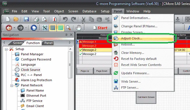
Ensure that you have a connection to the HMI. Select from the main menu | Panel | Adjust Clock…
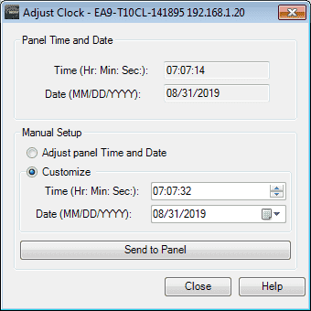
We can then set or adjust the time and hit the Send to Panel button. When you are finished, select the Close button.
Download the PLC and C-More program here.
Watch the video below to see the Alarm Objects in action on our C-More EA9 HMI Panel. This will also demonstrate the PLC ladder code for functionality.
C-More EA9 Panels from Automation Direct
https://www.automationdirect.com/adc/shopping/catalog/hmi_(human_machine_interface)/c-more_touch_panels_ea9_series
C-More – Graphic Panel (EA9 Series) User Manual and Quick Start Guides
https://cdn.automationdirect.com/static/manuals/ea9userm/ea9userm.html
EA9-T10CL C-More Specifications
https://cdn.automationdirect.com/static/specs/ea9t10cl.pdf
C-More EA9 Programming Software (Current Version V6.42)
https://support.automationdirect.com/products/cmore.html
This software will enable you to program all of the C-More EA9 HMI units. It includes a simulator for your application.
Next time we will look more at the object list text that we can use in the C-More HMI Panel.
Watch on YouTube: C-More EA9 HMI Series Panel Object List Alarms
If you have any questions or need further information please contact me.
Thank you,
Garry
If you’re like most of my readers, you’re committed to learning about technology. Numbering systems used in PLC’s are not difficult to learn and understand. We will walk through the numbering systems used in PLCs. This includes Bits, Decimal, Hexadecimal, ASCII and Floating Point.
To get this free article, subscribe to my free email newsletter.
Use the information to inform other people how numbering systems work. Sign up now.

The ‘Robust Data Logging for Free’ eBook is also available as a free download. The link is included when you subscribe to ACC Automation.