A PID (Proportional, Integral, and Derivative) control is possible with the Click PLC. A sample program was written for this PLC by Bernie Carlton in the following thread from the Automation Direct Forum. This was based on the math/process presented by Tim Wescott on is paper titled PID without a Ph.D. We will be using this sample program along with a Factory IO scene to demonstrate PID control using our Click PLC.
Here are some references on PID control:
PID without a Ph.D. By Tim Wescott
Understanding PID in 4 minutes
PID Control – A brief introduction
PID Controllers Explained
Who Else Wants to Learn about On-Off and PID Control?
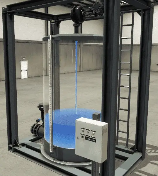
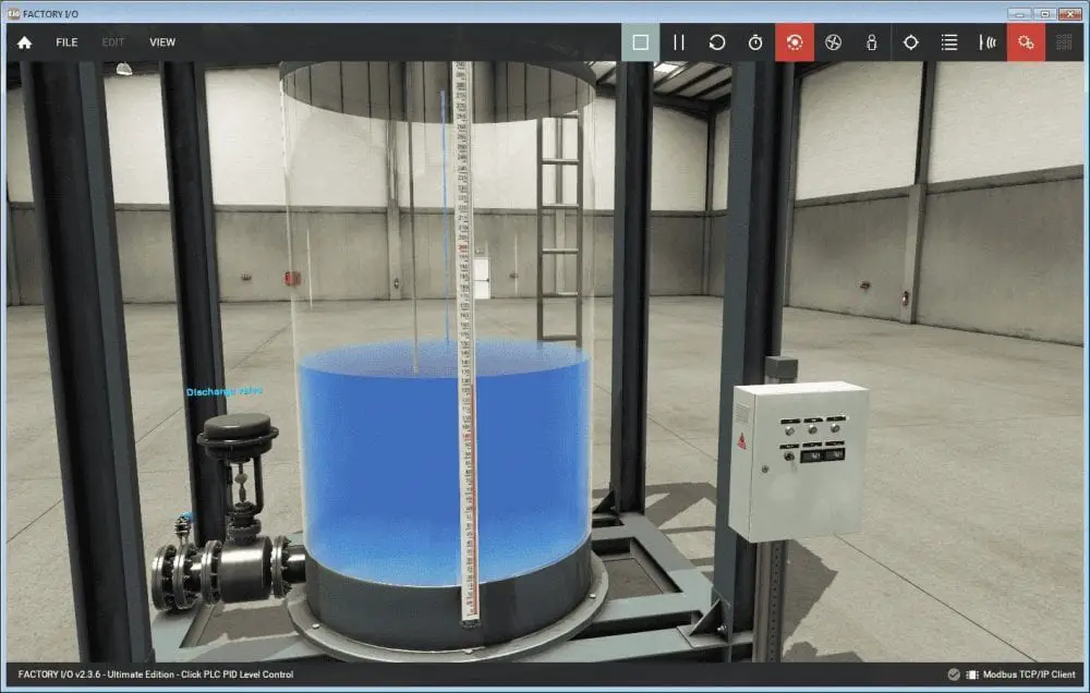
Our Factory IO scene will be controlling the level of water in a tank. PID will be used to maintain the level based on a dial pot knob on the control panel. We will also discuss the math that the PID loop uses. Let’s get started!
Previously in this series, we have discussed:
System Hardware – Video
Installing the Software – Video
Establish Communication – Video
Numbering System and Addressing – Video
Timers and Counters
– Counter Video
– Timer Video
Compare and Math Instructions – Video
Program Control Instructions – Video
Shift Register – Video
Drum Instruction – Video
Send and Receive Instructions – Video
AdvancedHMI Communication – Video
Firmware Update – Video
HMI Rotary Encoder Dial Input – Video
High Speed Counters Part 1
– High-Speed Count Mode Video
– Interval Measurement Mode Video
– Duration Measurement Mode Video
– Frequency Measurement Mode Video
High Speed Counters Part 2
– External Interrupt Mode Video
– Pulse Catch Mode Video
– Filter Pulse Mode Video
– Frequency Measurement and High-Speed Count Mode Video
Wiring Stack Light to Click PLC – Video
Wiring Push Buttons and Selector Switch to Click PLC – Video
– Test and Assembly of Push Buttons and a Selector Switch – Video
Wiring an Inductive Proximity NPN PNP Sensor to the Click PLC – Video
Wiring a Capacitive Proximity NPN PNP Sensor to the Click PLC – Video
Wiring an Ultrasonic Proximity Sensor to the Click PLC – Video
– Unboxing our UK1F Ultrasonic Proximity Sensor – Video
Analog Dusk to Dawn Program – Video
Our entire series can be found here.
The programming software and manuals can be downloaded from the Automation Direct website free of charge.
Watch the video below to see the PID program on our Click PLC controlling the Factory IO tank level scene.
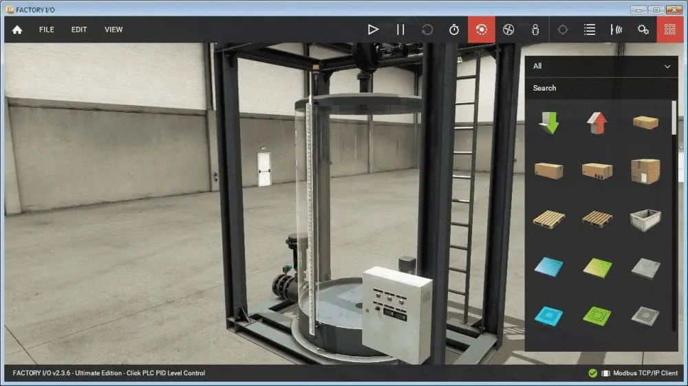
Factory IO (3D)

Factory IO is a 3D training software for PLC programming. You can Practice real-world control tasks with more than 20 scenes inspired by common industrial applications. Creating your own training scenarios is also possible by using a palette of industrial parts.
Start Factory IO and select Scenes.
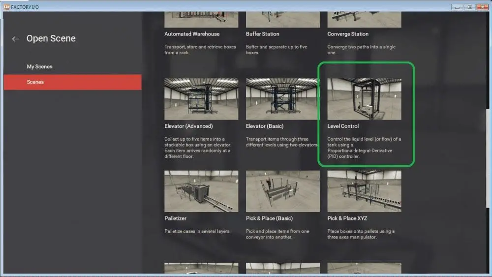
Scroll down to Level Control and double click on this scene. This will now display the level control scene on your software.
Select File | Drivers from the main menu. Alternatively, you could also select F4 to get to the drivers.
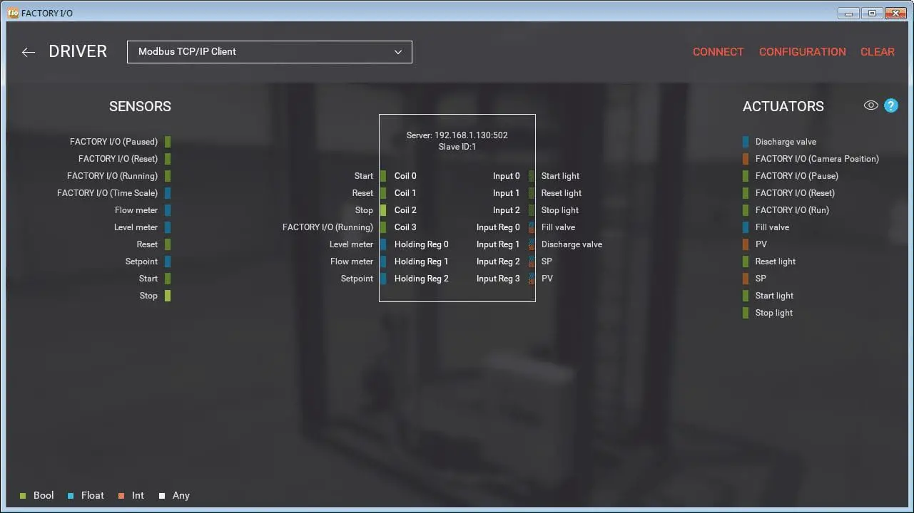
Select Modbus TCP/IP Client next to the Driver. This will set up the IO required for the scene that we have just selected. Select configuration from the top-right main menu.
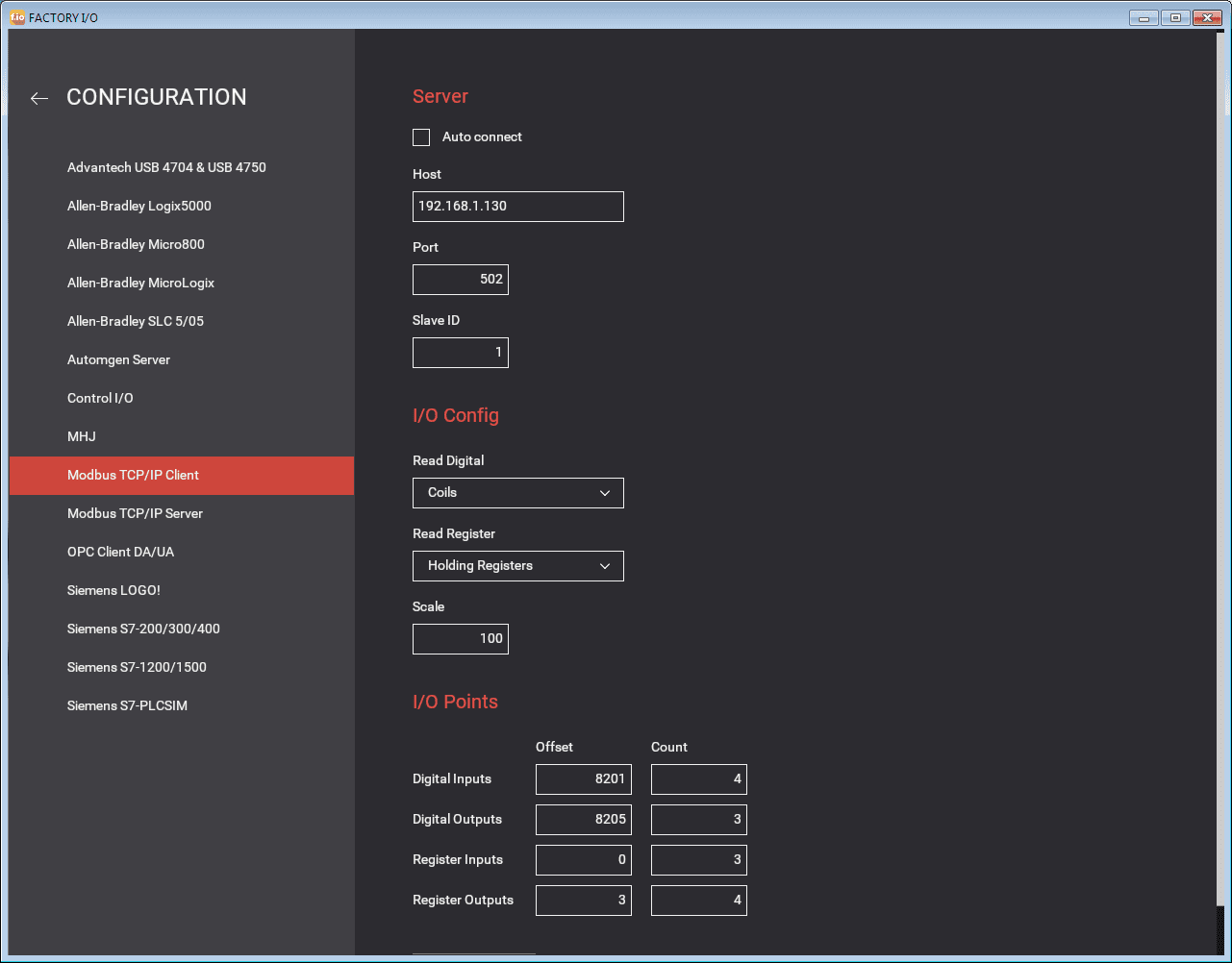
We will use the following parameters for our application. Remember that the Client (Master) will send information and the Server (Slave) will respond to the information sent.
Server
Host – 192.168.1.130
Port – 502 – This is the default port for Modbus TCP
Slave ID – 1
I/O Config
Read Digital – Coils – The Click cannot set an input area as an output. Example: X10 cannot be used as an output. All discrete input/outputs will be in the Y area.
Read Register – Holding Registers – All values used will be in the DS area.
Scale – 100 – Default
I/O Points
Digital Inputs – Offset 8201 – Count 4
Digital Outputs – Offset 8205 – Count 3
Register Inputs – Offset 0 – Count 3
Register Outputs – Offset 3 – Count 4
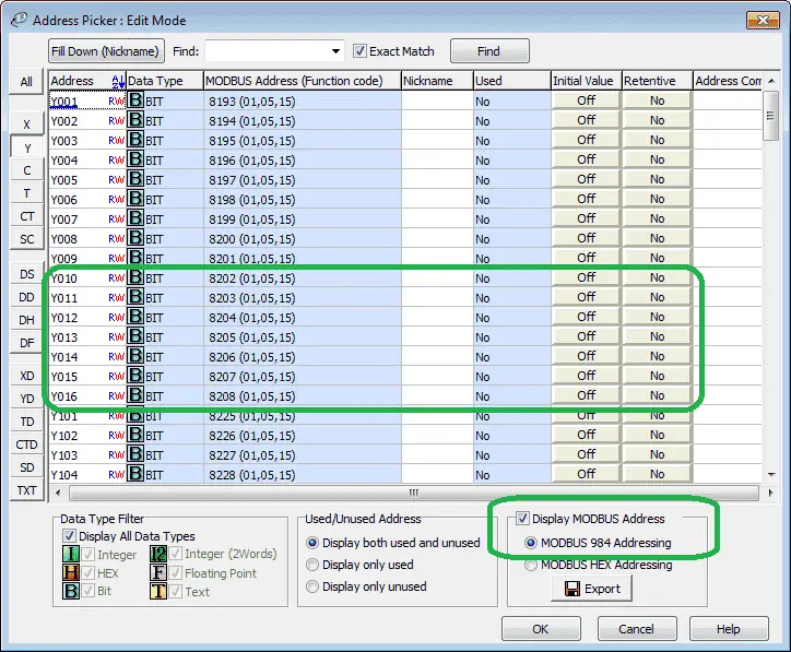
If we call up the address picker in the Click programming software and select display Modbus address, it will show how we obtained the offset values.
Note: The values are also offset by a value of 1 between the Click PLC and Factory IO.
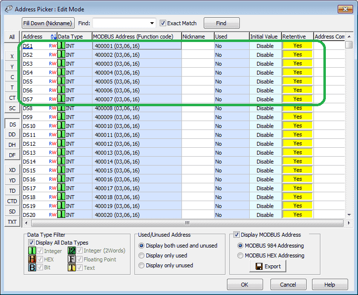
Here is the DS area of the Click PLC showing the Modbus addresses.
In general here is how the addressing works on standard Modbus.
Discrete Output Coils – 00001 – 09999
Discrete Input Coils – 10001 – 19999
Analog Input Registers – 30001 – 39999
Analog Output Holding Registers – 40001 – 49999
Inputs / Outputs – Factory IO
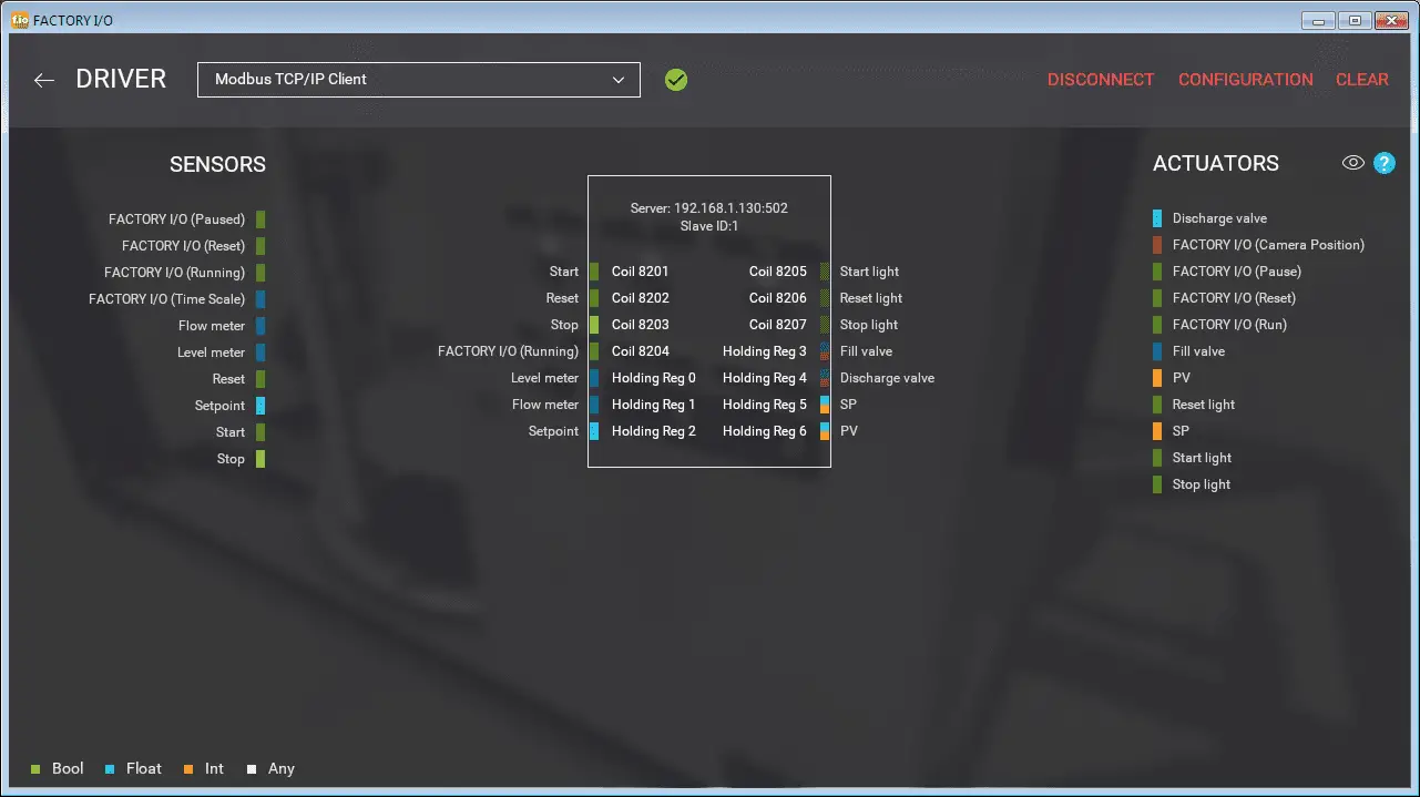
The Click PLC has fixed Modbus addresses. Modbus addresses are offset by 1 in Factory IO for the Click PLC. The following is a summary of our inputs and outputs to the Click PLC.
Start – Coil 8201 – Click Y10 – Modbus 008202
Reset – Coil 8202 – Click Y11 – Modbus 008203
Stop – Coil 8203 – Click Y12 – Modbus 008204
Factory I/O Running – Coil 8204 – Click Y13 – Modbus 008205
Level Meter – Holding Reg 0 – Click DS1 – Modbus 400001
Flow Meter – Holding Reg 1- Click DS2 – Modbus 400002
Setpoint – Holding Reg 2- Click DS3 – Modbus 400003
Start Light – Coil 8205 – Click Y13 – Modbus 008206
Reset Light – Coil 8206 – Click Y14 – Modbus 008207
Stop Light – Coil 8207 – Click Y15 – Modbus 008208
Fill Valve – Holding Reg 3- Click DS4 – Modbus 400004
Discharge Valve – Holding Reg 4- Click DS5 – Modbus 400005
SP Setpoint – Holding Reg 5- Click DS6 – Modbus 400006
PV Present Valve – Holding Reg 6- Click DS7 – Modbus 400007
Select the Connect button to connect to the Server. You will see the IO light up as the input/outputs are energized. Also, note that the checkmark beside the driver means that we are connected.
Start Factory IO
Our driver has been now selected and configured. We now know the addresses of our application.
Select the play button (right arrow) from the main menu to enable the scene to operate.
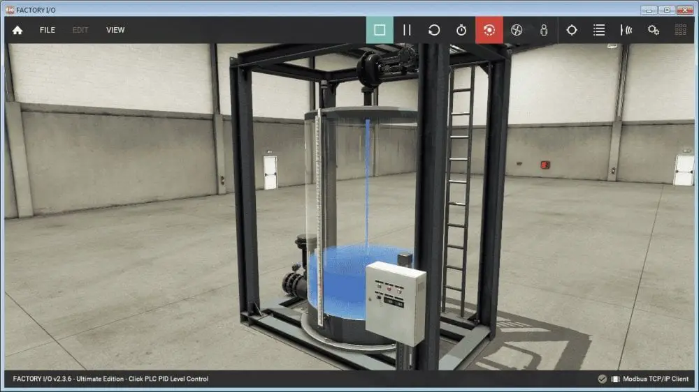
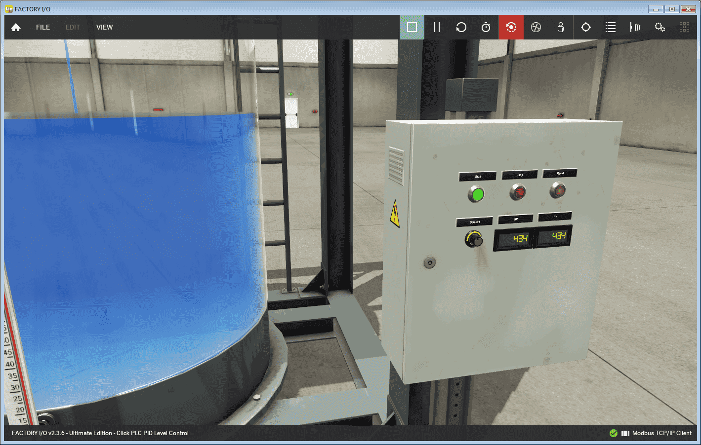
We can now operate the panel based on the IO interaction between Factory IO and the Click PLC. Watch the video below to see the level control program in action on our Click PLC.
Click PLC Hardware
Our hardware includes the following:
C0-11DRE-D – Click CPU with Ethernet
Note: Click Ethernet CPU with analog is also available.
C0-4AD2DA-2 – Click Analog Card 4 inputs / 2 outputs
C0-01AC – Click 24VDC power supply
Ladder Program – PID Math Calculation
The ladder logic and Factory IO scene can be downloaded below.
We will first look at the PID Interrupt routine.
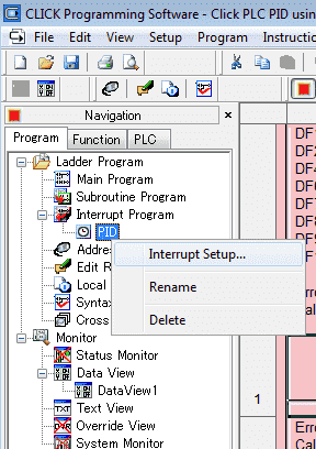
PID is located under the Interrupt Program under the Ladder Program in the Navigation menu.
Right-click the PID interrupt program and select Interrupt Setup…
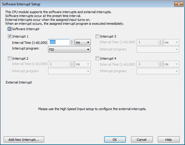
You will see that this is a Software Interrupt 1 that will be executed every 100 ms or 10 times per second. Select OK to close the window.
The following are the parameters used in this interrupt.
DF1 = process variable input
DF2 = set point input
DF4 = calculated control output
DF6 = I max windup input
DF7 = I min windup input
DF8 = P gain input
DF9 = I gain input
DF10 = D gain input
Calculate Error
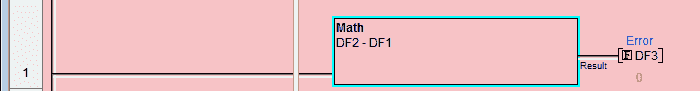
Error is setpoint – position (or the opposite for reverse acting)
Calculate PE: SP – PV -> Store in var ‘PE’
Calculate pTerm
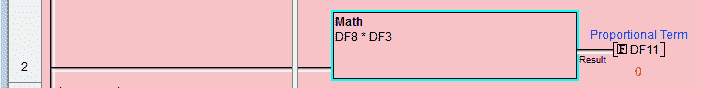
Error * Gain
Calculate pTerm: PE * pGain -> Store in var ‘pTerm’
Calculate iTerm
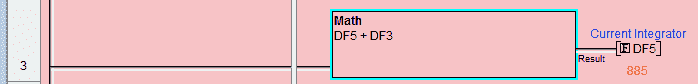 Integrate the error. This is the sum of the error over time.
Calculate Integral= PE + Integral -> Store in var Integral
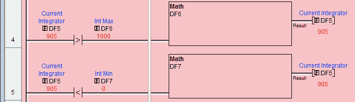
Limit the loop bias. Set the maximum and minimum Integral.
Calculate iTerm = Integral * iGain – Store in var iTerm
Calculate dTerm
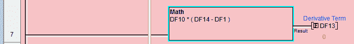
Calculate dTerm = (PV – Derivative) * dGain -> Store in dTerm
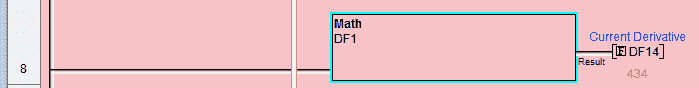
Calculate Derivative: Derivative = PV -> Store in var Derivative
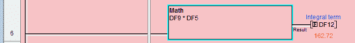
Calculate the PID Control Output
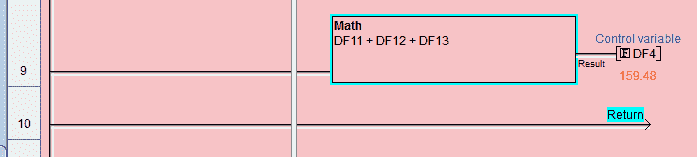
Calculate PID Control Output: pTerm + iTerm – dTerm -> Store in var PIDOUT
Click PLC Main Program
The main program will start and stop the process. This will control the Factory IO scene based on the IO addressing determined above.
Start and stop the PID loop from the buttons on the Factory IO Level Scene.
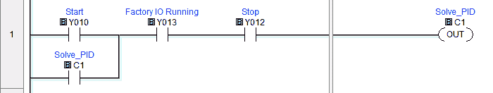
C1 is used to start/stop the output of the PID to the fill valve of the Factory IO scene.

Indication lights on the Factory IO panel.
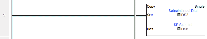
Move the Factory IO panel setpoint dial position into the setpoint display on the factory IO panel.
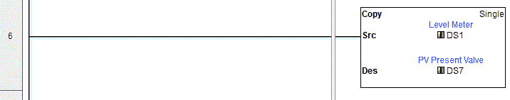
Move the Factory IO level meter position into the present value (PV) display on the factory IO panel.
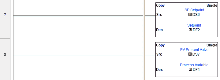
Move the setpoint value (SV) and present value (PV) values into the PID loop parameters.
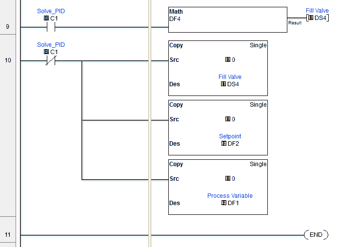
If C1 is on then the fill valve is used to control the water going into the tank based on the PID output. If C1 is off then the fill valve is closed.
Watch the video below to see the PID using Factory IO program in action on our Click PLC.
Download the Click PLC and Factory IO Scene programs here.
Next time we will be using the new PID instruction in the Click PLC. This instruction is available for all Ethernet-based Click controllers running software version 2.50.
Click PLC Support Links
The Click PLC can be programmed using free Click programming software from Automation Direct. Here is a link for the software.
https://support.automationdirect.com/products/clickplcs.html
The following links will help you to install the software and establish communication.
https://accautomation.ca/click-plc-installing-the-software/
https://accautomation.ca/click-plc-establish-communication/
The entire Click PLC series can be found at the following URL:
https://accautomation.ca/series/click-plc/
Watch on YouTube: Click PLC PID using Factory IO
If you have any questions or need further information please contact me.
Thank you,
Garry
If you’re like most of my readers, you’re committed to learning about technology. Numbering systems used in PLC’s are not difficult to learn and understand. We will walk through the numbering systems used in PLCs. This includes Bits, Decimal, Hexadecimal, ASCII and Floating Point.
To get this free article, subscribe to my free email newsletter.
Use the information to inform other people how numbering systems work. Sign up now.

The ‘Robust Data Logging for Free’ eBook is also available as a free download. The link is included when you subscribe to ACC Automation.