We will be demonstrating counter-sequencing logic on the Do-More PLC Simulator and EasyPLC. EasyPLC software suite includes a machine simulator named Machine Simulator (MS). It has a variety of machines that can be programmed and customized. One of these machines is the body car quality verification machine, which utilizes a camera and a collaborative robot (cobot) to check the body and a second cobot to mark the inspection pass. If the inspection fails, a robot will return the car’s body. The virtual machine will be programmed using the Do-More Designer PLC Simulator.
To establish communication between the simulator and the quality verification machine, we will use the Do-More Designer PLC software and connect them via Modbus TCP (Ethernet). This will enable seamless communication and data exchange between the two systems.
To demonstrate the programming of the virtual machine, we will follow the five steps for program development. These steps provide a structured approach to ensure the efficient and effective development of the ladder logic program. By following these steps, we can ensure that the program meets the specifications and functions as intended.
Now, let’s dive into the first step of the program development process. This step involves defining the task of our car body product quality verification. By clearly defining the task, we can establish the objectives and requirements that the program needs to fulfill. This will serve as the foundation for the subsequent steps in the development process.
Learn PLC programming the easy way. See below how to receive a 10% discount on this cost-effective learning tool. Invest in yourself today.
Previously, we have done the following:
Easy PLC Installing the Software – Video
EasyPLC Software Suite – Quick Start – Video
Click PLC – Easy Transfer Line Programming – Video
Productivity PLC Simulator – Chain Conveyor MS – Video
Do-More PLC – EasyPLC Box Selection Program – Video
Click PLC EasyPLC Gantry Simulator – Video
Click PLC Simple Conveyor EasyPLC – Video
EasyPLC Paint Line Bit Shift – BRX Do-More PLC – Video
Click PLC – EasyPLC PLC Mixer Programming – Video
Click PLC EasyPLC Warehouse Stacker Example – Video
– Operation Video
EasyPLC Machine Simulator Productivity PLC Robotic Cell – Video
EasyPLC Simulator Robotic Cell Click PLC – Video
Palletizing Conveyor Programming Do-More PLC – Video
Palletizing Conveyor Programming – Click PLC – Video
Define the task: (Step 1 – Product Quality Verification)
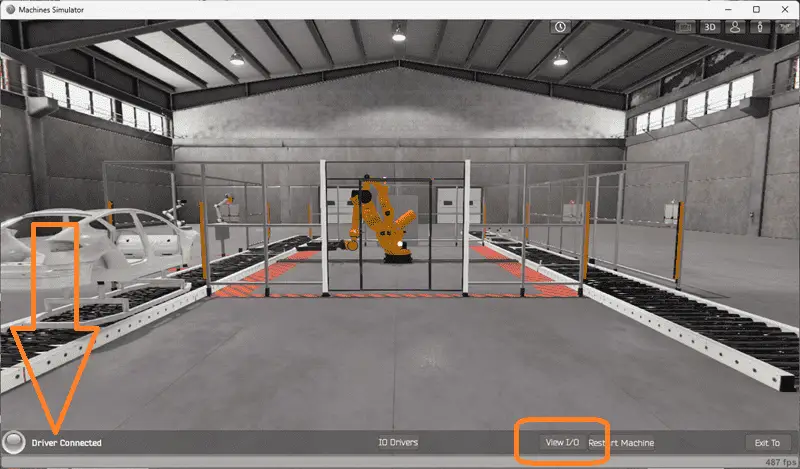
The first step of a Do-More or any PLC program development is determining what must be done. Start the EasyPLC Machine Simulator (MS). Select the start button on the main page or select machines from the main menu at the machines simulator window.
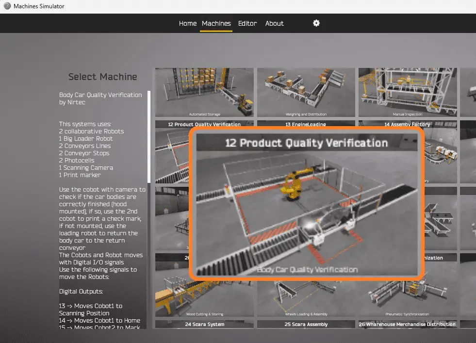
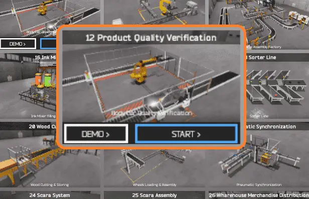
All the available machines will now be displayed. Click on the “12 Product Quality Verification”. This is the example we will be programming. To the left of the screen, information will be displayed on how the car body quality verification machine needs to function. This system uses two collaborative robots, one giant loader robot, two conveyor lines, two conveyor stops, two photocells, one scanning camera, and one print marker. Use the cobot with the camera to check if the car bodies are correctly finished. (Hood mounted) If so, use the second cobot to print a check mark. If not mounted, use the loading robot to return the car body to the return conveyor. The cobots and robots move with digital inputs and output signals.
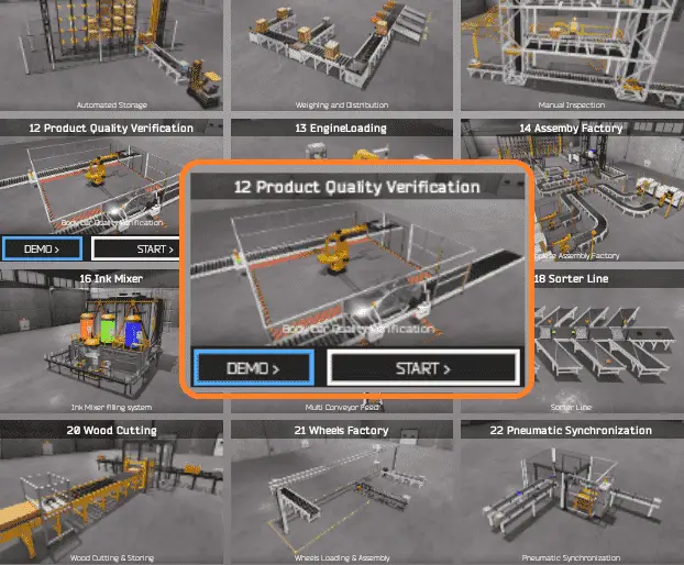
The body car quality verification simulator has a demo mode for this built-in machine. This will allow you to watch the operation of the product quality verification machine. Select the demo mode for quality verification. The demo mode will show you the basics of the quality verification operation.

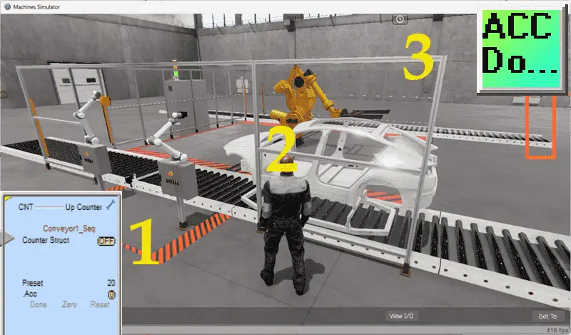
Move around the 3D virtual environment. The icons on the top of the window allow you to move around this 3D environment.
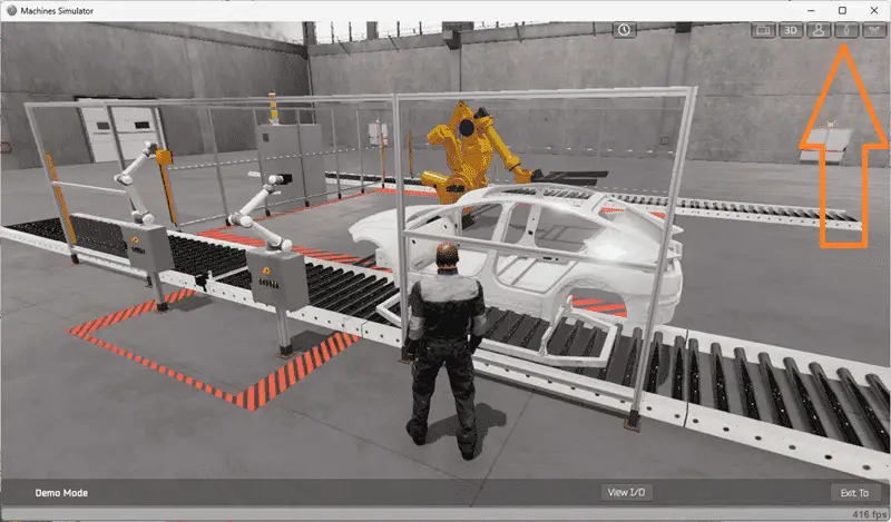
The first icon is the default selection. This will enable you to move around without bumping into the components. The last icon will automatically show you around this virtual environment. The first-person mode will mimic a person in your 3D learning world. The third person will show you an operator and their relationship to the palletizing machine. Once we understand what must be done, we can move on to the next step in developing the Do-More PLC ladder logic program.
Watch the sequence of operation video below.
Define the Inputs and Outputs: (Step 2 – Product Quality Verification)
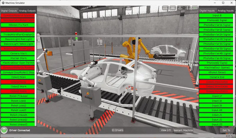
While still in demo mode, select View IO at the bottom of the machine simulator window. This will display the inputs and outputs required for this product quality verification.
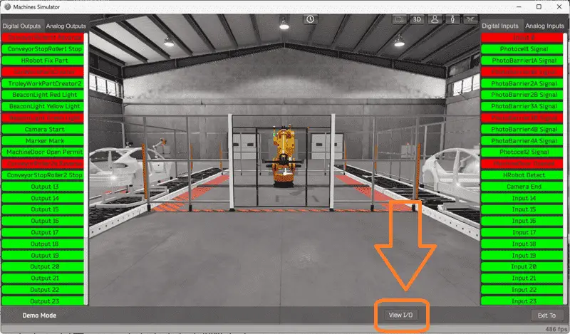
The EasyPLC quality verification Do-More example will require 29 digital outputs and 18 digital inputs.
The camera result will require one analog input to determine if a car hood has been attached or not.
If you are unsure what output or input is doing, start the product quality verification in Start mode. Select the View IO on the bottom middle of the machine simulator window. You can manually run the product quality verification without any control or PLC connection.
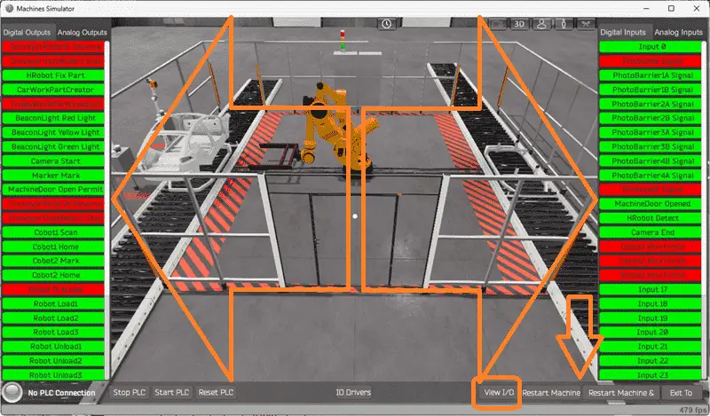
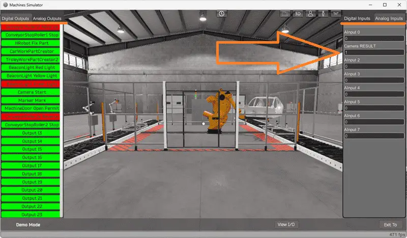
Clicking on the outputs will allow you to turn them on manually. You can then monitor the inputs to see their operation. Move around in the 3D environment and see the IO and items from different angles. Clicking on the analog will call up the analog IO for you to monitor and interact. The restart button on the bottom of the machine simulator window will reset the scene back to the start.
The Do-More Series of PLCs uses a fixed Modbus memory area. This area can be seen in the following chart.
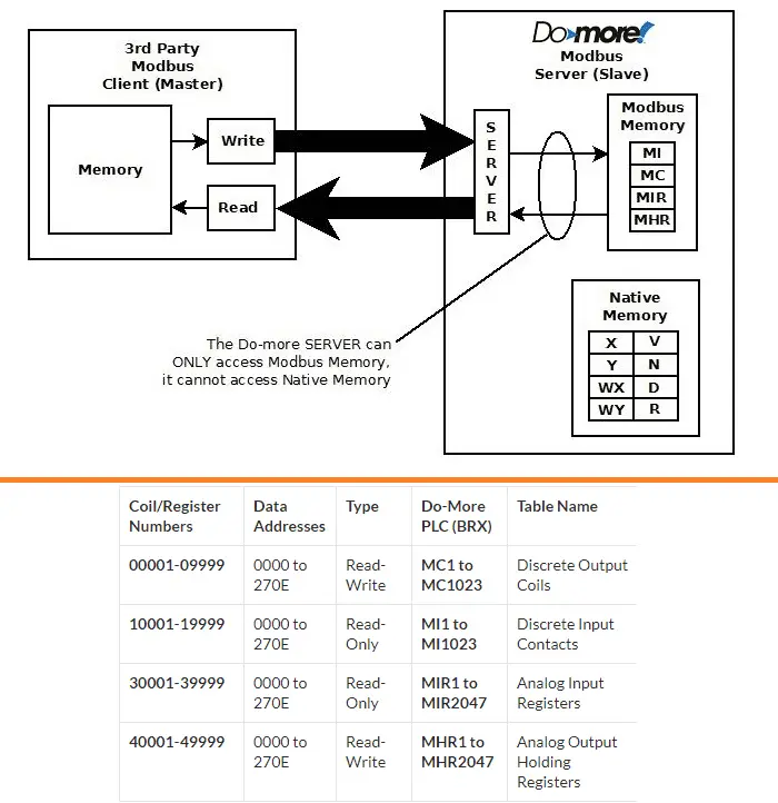
The following table will define the inputs and outputs (IO) and Modbus addresses in the Do-More Designer Simulator we will use for this program.
| Digital Type | Description | Productivity Modbus Address | Machine Simulator Modbus Address |
| PLC Output – MS Input | Conveyor Roller 1F Advance | 10001 – MI1 | 0 |
| PLC Output – MS Input | Conveyor Stop Roller1 | 10002 – MI2 | 1 |
| PLC Output – MS Input | HRobot Fix Part | 10003 – MI3 | 2 |
| PLC Output – MS Input | Car WorkPartCreator | 10004 – MI4 | 3 |
| PLC Output – MS Input | Trolley WorkPartCreator | 10005 – MI5 | 4 |
| PLC Output – MS Input | Red Beacon Light | 10006 – MI6 | 5 |
| PLC Output – MS Input | YellowBeacon Light | 10007 – MI7 | 6 |
| PLC Output – MS Input | Green Beacon Light | 10008 – MI8 | 7 |
| PLC Output – MS Input | Camera Start | 10009 – MI9 | 8 |
| PLC Output – MS Input | Marker Mark | 10010 – MI10 | 9 |
| PLC Output – MS Input | Machine Door Open Permit | 10011 – MI11 | 10 |
| PLC Output – MS Input | Conveyor Roller 2E Reverse | 10012 – MI12 | 11 |
| PLC Output – MS Input | Conveyor Stop Roller2 | 10013 – MI13 | 12 |
| PLC Output – MS Input | Cobot1 Scan | 10014 – MI14 | 13 |
| PLC Output – MS Input | Cobot1 Home | 10015 – MI15 | 14 |
| PLC Output – MS Input | Cobot2 Mark | 10016 – MI16 | 15 |
| PLC Output – MS Input | Cobot2 Home | 10017 – MI17 | 16 |
| PLC Output – MS Input | Robot Preload | 10018 – MI18 | 17 |
| PLC Output – MS Input | Robot Load1 | 10019 – MI19 | 18 |
| PLC Output – MS Input | Robot Load2 | 10020 – MI20 | 19 |
| PLC Output – MS Input | Robot Load3 | 10021 – MI21 | 20 |
| PLC Output – MS Input | Robot Unload1 | 10022 – MI22 | 21 |
| PLC Output – MS Input | Robot Unload2 | 10023 – MI23 | 22 |
| PLC Output – MS Input | Robot Unload3 | 10024 – MI24 | 23 |
| PLC Output – MS Input | Robot Unload4 | 10025 – MI25 | 24 |
| PLC Output – MS Input | Robot Move to Load Position | 10026 – MI26 | 25 |
| PLC Output – MS Input | Robot Move to Unload Position | 10027 – MI27 | 26 |
| PLC Output – MS Input | Robot Move to Home Position | 10028 – MI28 | 27 |
| PLC Output – MS Input | Get Robot X Pos | 10029 – MI29 | 28 |
| PLC Input – MS Output | Input 0 | 1 – MC1 | 0 |
| PLC Input – MS Output | PhotoCell 1 Signal | 2 – MC2 | 1 |
| PLC Input – MS Output | PhotoBarrier 1A Signal | 3 – MC3 | 2 |
| PLC Input – MS Output | PhotoBarrier 1B Signal | 5 – MC5 | 4 |
| PLC Input – MS Output | PhotoBarrier 2A Signal | 6 – MC6 | 5 |
| PLC Input – MS Output | PhotoBarrier 2B Signal | 7 – MC7 | 6 |
| PLC Input – MS Output | PhotoBarrier 3A Signal | 8 – MC8 | 7 |
| PLC Input – MS Output | PhotoBarrier 3B Signal | 9 – MC9 | 8 |
| PLC Input – MS Output | PhotoBarrier 4A Signal | 10 – MC10 | 9 |
| PLC Input – MS Output | PhotoBarrier 4B Signal | 11 – MC11 | 10 |
| PLC Input – MS Output | PhotoCell 2 Signal | 12 – MC12 | 11 |
| PLC Input – MS Output | Machine Door Open | 13 – MC13 | 12 |
| PLC Input – MS Output | HRobot Detect | 14 – MC14 | 13 |
| PLC Input – MS Output | Camera End | 15 – MC15 | 14 |
| PLC Input – MS Output | Cobot1 Move Finish | 16 – MC16 | 15 |
| PLC Input – MS Output | Cobot2 Move Finish | 17 – MC17 | 16 |
| PLC Input – MS Output | Robot1 Move Finish | 18 – MC18 | 17 |
| Analog PLC Input – MS Output | AInput 0 | 40011 – MHR11 | 10 |
| Analog PLC Input – MS Output | Camera Result | 40012 – MHR12 | 11 |
Note: The machine simulator will be offset by one on the Modbus Addresses.
Develop a logical sequence of operation: (Step 3 – Product Quality Verification)
A flow chart or sequence table is used to understand the process that must be controlled fully. It must also answer questions like this:
What happens when electrical power and/or pneumatic air is lost?
What happens when the input/output devices fail?
Do we need redundancy?
This step is where you can save yourself a lot of work by understanding everything about the operation. It will help prevent you from continuously re-writing the PLC program logic. Knowing all of these answers upfront is vital in developing the PLC program.
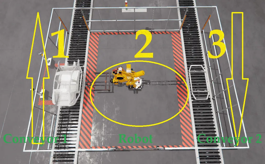
Our Do-More product quality verification machine can be broken down into three sequencers.
1 – Conveyor 1 sequencer will allow car bodies to enter the inspection station. The car body will be positioned at the conveyor one stopper. A camera on a collaborative robot is used to determine if a car hood is present or not. If present, the body is marked by a second collaborative robot and sent out of the inspection station. If the hood is absent, the conveyor one sequencer will wait until a robot picks up the car body and moves to the home position. The camera returns to the home position, and the carrier is sent out of the inspection station.
2 – The robot sequencer will pick up the car body without the hood (defect) and transfer it to the empty carrier on the returning conveyor 2.
3 – The conveyor two sequencer will allow an empty carrier to enter the inspection station. If the robot places a car body onto the carrier and returns to the home position, the carrier with the defective car body will exit the inspection station.
A PLC programmer must know everything about the sequence and operation of the machine before programming.
Ask questions or view existing documentation to ensure you know the logical steps to the machine’s operation.
Develop the Do-More PLC program (Step 4 – Product Quality Verification)
Writing the ladder logic code for the PLC example will be the next step in our program development. Detailed information on the Do-More PLC and simulator can be found here. We will be using the Do-More Simulator with our EasyPLC Machine Simulator.
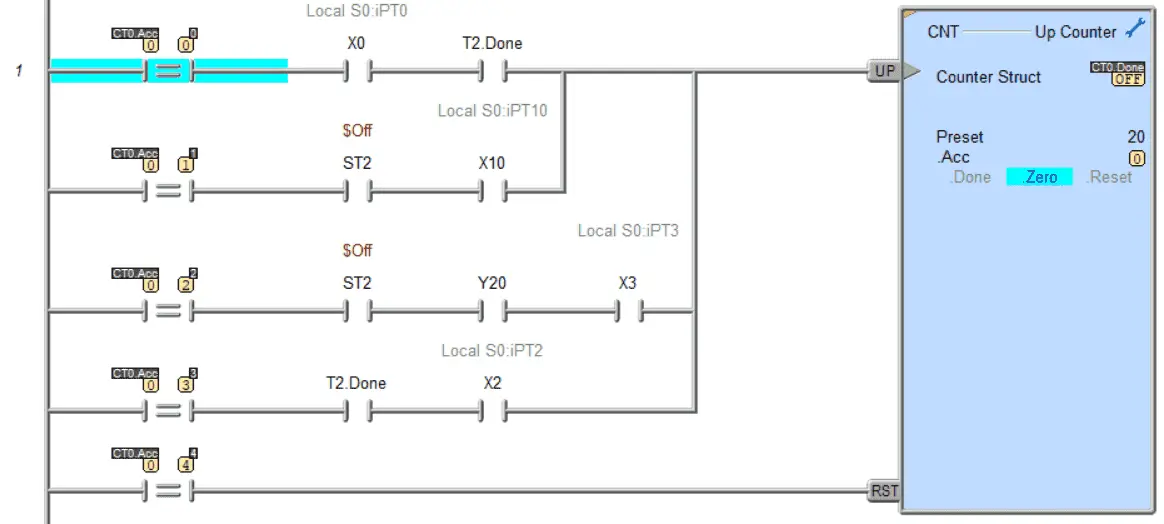
Counters will be used for the sequencers in our ladder logic program example. It is essential to understand how this is achieved so that you can easily read the PLC code. Incrementing the counter is done by comparing the current count value and the conditions (inputs) required to advance the sequencer step. After the last step increment, the counter is reset, which resets the sequence. We can easily control the sequence when developing the ladder logic code by placing the normally off contact so the counter will not advance to the next step.
Outputs are activated by comparing the current step. If the outputs are activated multiple times in the sequence, the comparing steps are placed in parallel.
The following is our Do-More ladder logic programming sample code with three counter sequencers. You will see that the ladder logic does not have many rungs and is easy to troubleshoot and program.
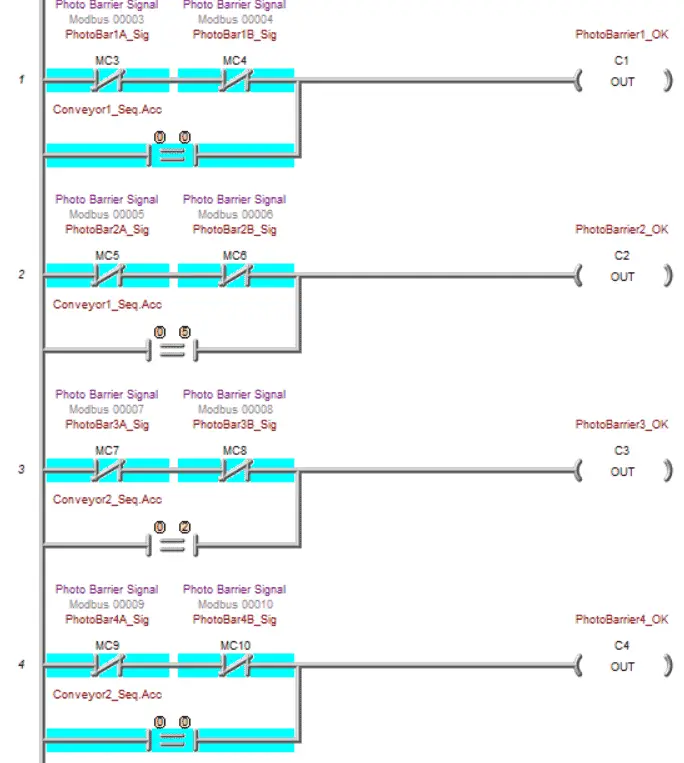
The first four rungs of the Do-More quality verification program will create bits to indicate that the photo barriers are OK. You will see the conveyor sequence step from the counters that will allow the product to pass through.
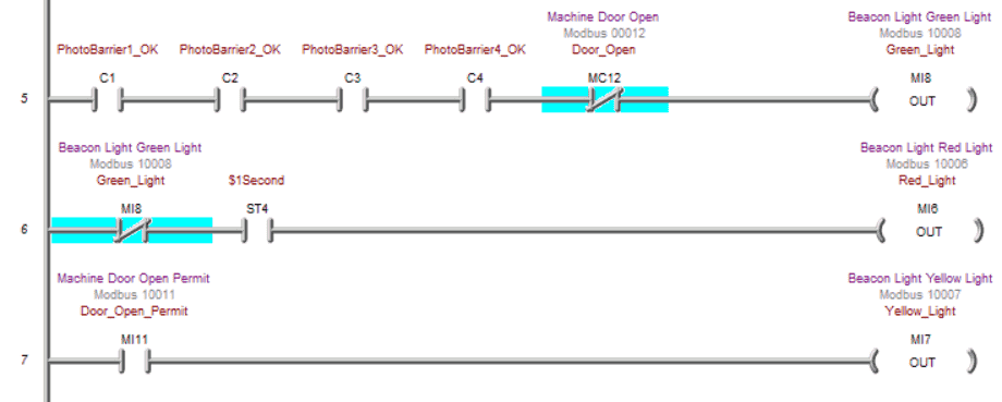
Here are our indication lights for the machine. The green light will be on when the photo barriers and the door of the machine are not open. A flashing 1-second pulse is used for the red light when the green light is not on. Our yellow light is on when the door open permit is energized.
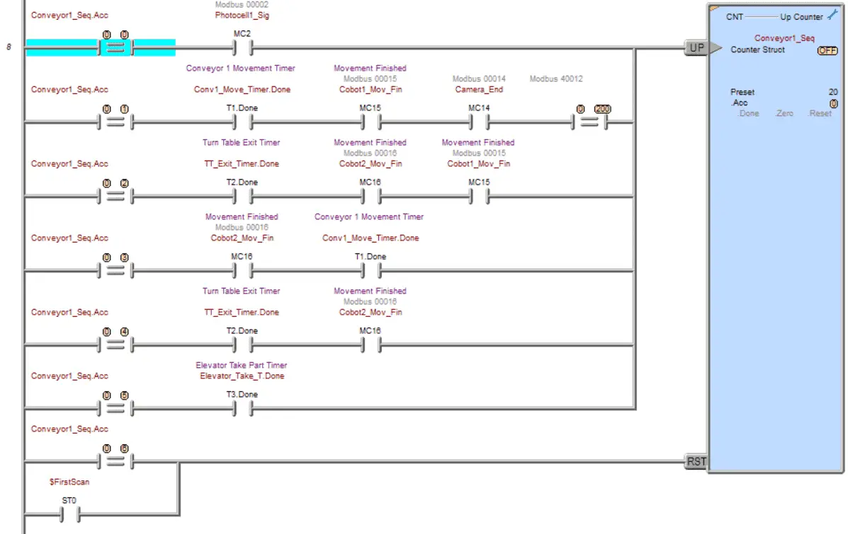
Counter 1 is used for the conveyor one sequencer. When the hood for the car is present, this sequencer will cycle through the six steps without activating the robot or conveyor two sequencers.
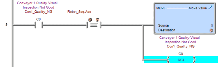
If the quality is not good and the hood is missing, bit C0 will be set internally. When the robot sequence is at step 6, a move instruction is used in the do-more PLC to set the sequence number of conveyor 1. This will send the empty carrier out of the quality inspection station and reset the sequencer.
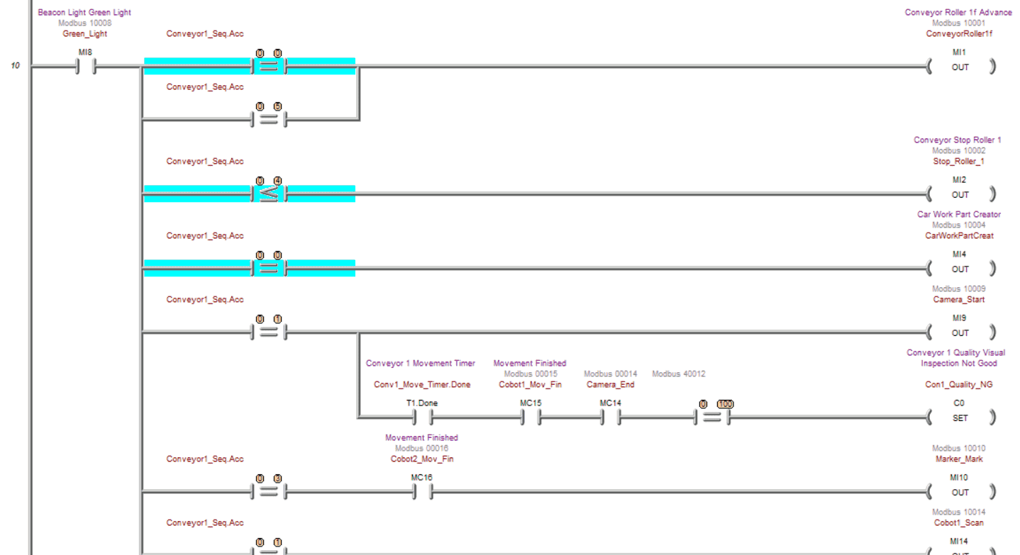
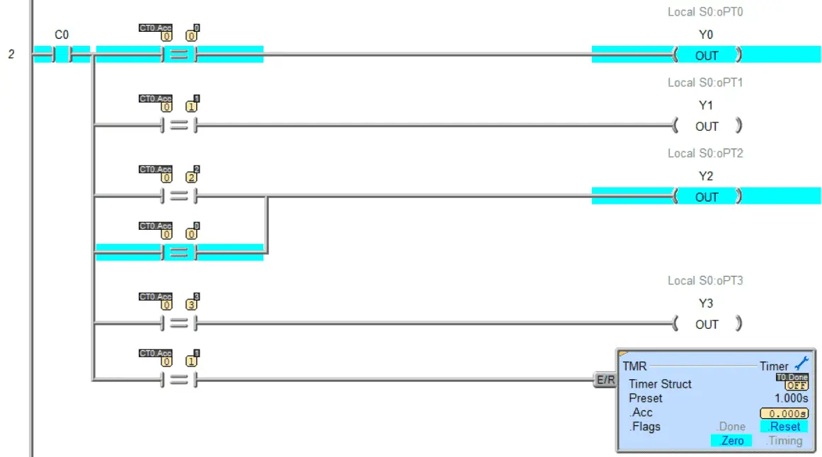
Rung 10 will control the outputs associated with the conveyor one sequencer. You will see this is all based upon the counter one accumulator value, which determines what step we are on. C0 is set if the quality inspection fails to see a hood on the car.
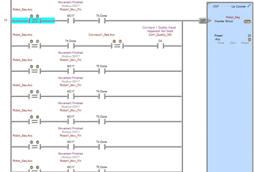
The do-more counter for the robot sequencer will use two timers. This will allow for the movement of the robot to start before looking for the move finished input to the Do-More PLC.
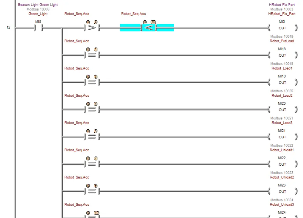
The robot sequencer accumulator controls outputs. You will see that the timers used in the do-more will have multiple parallel rungs for their activation.
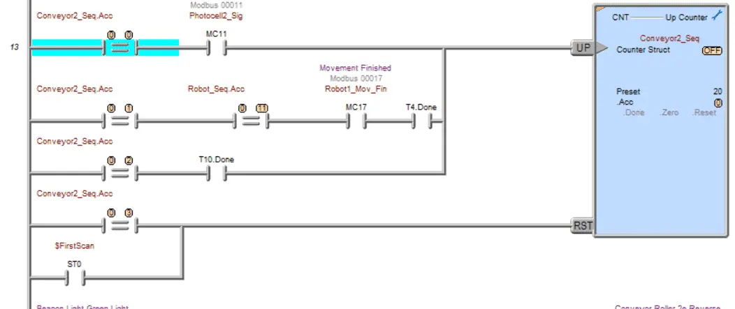
Rung 13 has a counter that controls the conveyor’s two sequences. Note that a first scan flag is used to reset all of the sequencers used in the ladder logic program. The first scan will activate when the power is applied in run mode or the Do-More transitions from program to run mode.
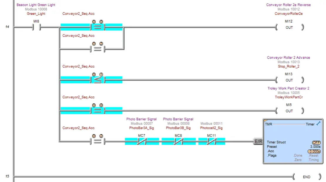
The timer used in the last step is to allow the carrier with the car body to exit through the photo barrier. Our Do-More ladder logic is complete.
Call up the system configuration in the Do-More Designer Software.
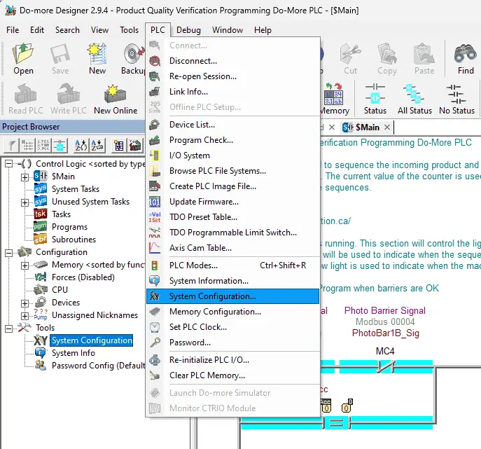
This is done by selecting System Configuration from the main menu | PLC | System Configuration.
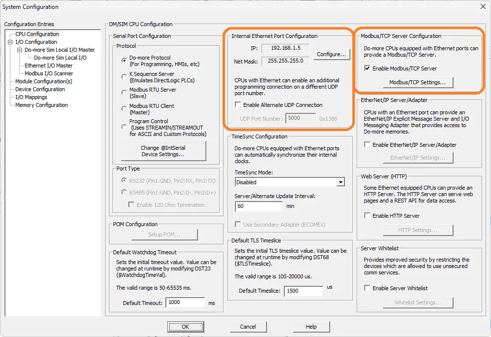
This will show us the current IP address of the Do-More Designer Simulator and will ensure that the Modbus TCP server is enabled. The IP address is the same as the computer it is running on. Ensure that you transfer the program to the Do-More Simulator PLC.
Test the program: (Step 5 – Product Quality Verification)
We will use Modbus TCP on our Do-More PLC simulator to communicate with the EasyPLC Machine Simulator. Call up the product quality verification machine simulator in start mode.
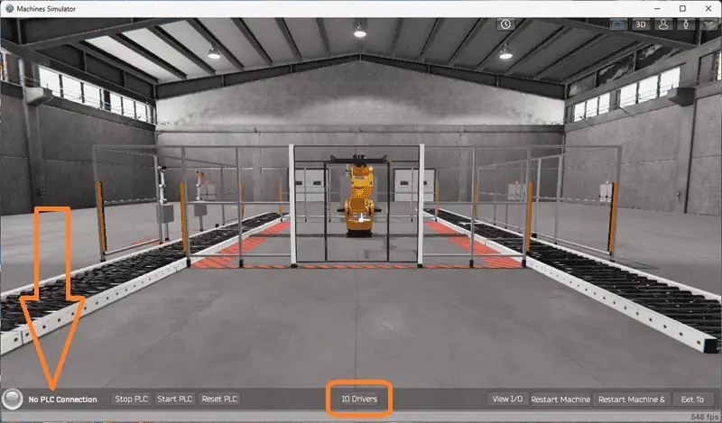
The status of the machine simulator will be at the bottom of the screen. Currently, we have no PLC connected. Select IO Drivers on the bottom middle of the screen.
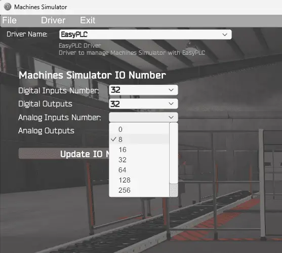
The machine simulator IO number will be displayed. Ensure we select more IO than the number required for our palletizing machine.
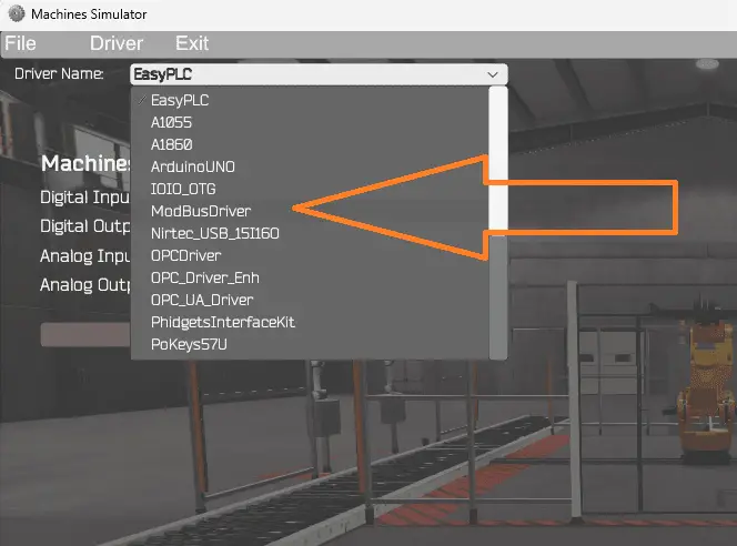
The EasyPLC driver is selected by default. Under the driver pull-down menu, select “ModBusDriver.” This driver will communicate Modbus TCP (Ethernet) and Modbus RTU (Serial).
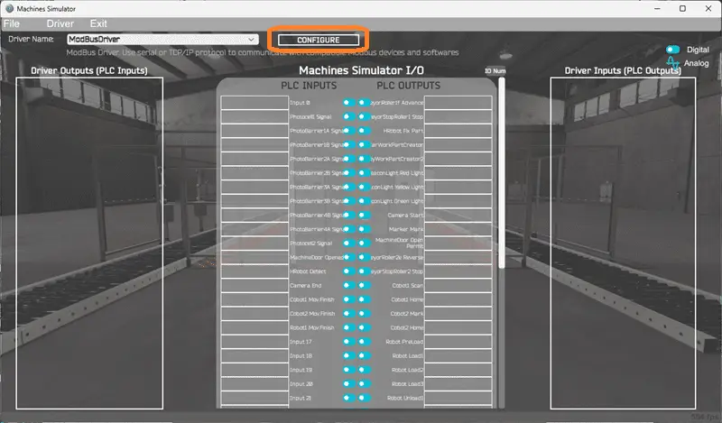
Select the configure button.
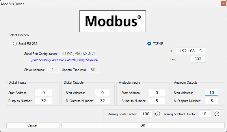
We can now enter the information for our Modbus driver. Select TCP/IP. This means the Ethernet port on the computer will communicate with the Do-More PLC simulator. The digital inputs from MS to the Do-More PLC will be MC1 to MC33. This will start at address 0 due to the offset of 1. Digital outputs from MS to the Do-More PLC will be MI1 to MI33. This will begin at address 0 due to the offset of 1. The analog inputs will start at 0 and be five registers. Analog outputs will begin at ten and also be set for five registers. This means the quality verification number (second output) will be addressed as MHR 12 for the camera output due to the offset of 1. Select the OK button.
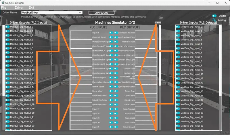
You will now see the inputs and outputs specified for the Modbus driver. We can now manually assign the driver outputs to the PLC inputs and driver inputs to the PLC outputs. However, the automatic assignment works well and will save you time.
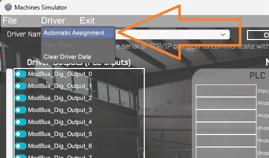
Select Automatic Assignment from the driver option in the main menu. This will automatically assign the PLC IO to the Machine Simulator IO.
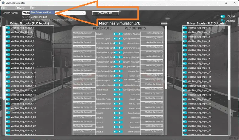
Select Start Driver and exit from the main menu.
On the bottom left side of the window, the driver communicates to the Do-More PLC simulator with the green light. Select view IO to know the input and output status of the machine simulator. Ensure that the Do-More PLC simulator is in run mode. We can see the operation of our palletizing machine.
The digital inputs and outputs of the MS will correspond to the PLC controller.
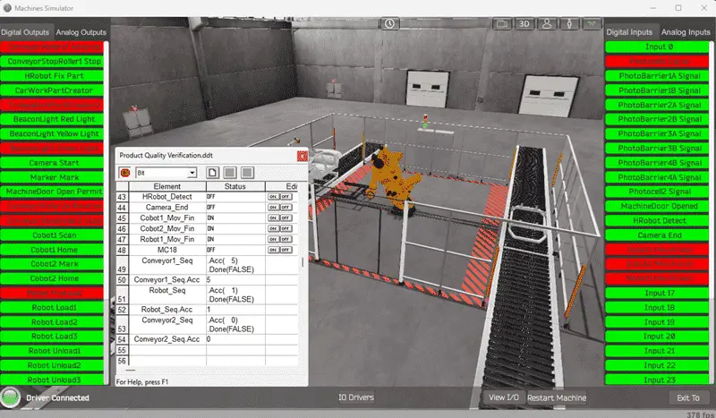
Using the Data View window of the Do-More Designer programming software, we can also watch the inputs and output operations. Using Machine Simulator (MS) to test the program will ensure that our program works. Troubleshooting is quickly done without damage to any physical hardware.
You can practice your modification and debug by modifying the quality visual inspection and Do-More program in the following way:
– Add a control panel with start and stop buttons.
– Add a jog button for each sequencer to the control panel to sequence through the steps.
– Calculate the rate of quality car parts coming out of the quality visual inspection machine in parts per hour.
– Calculate the rate of good vs poor quality car parts per shift.
Let me know how you make out in the comments below.
Download the Do-More PLC sample program here.
Watch the video below on the EasyPLC Product Quality Verification using Do-More counters as sequencers.
EasyPLC Software Suite is a complete PLC, HMI, and Machine Simulator Software package. This PLC learning package includes the following:
Easy PLC – PLC Simulation allows programming in Ladder, Grafcet, Logic Blocks, or Script.
HMI System – Easily create a visual human-machine interface (HMI)
Machine Simulator – A virtual 3D world with real-time graphics and physical properties. PLC programs can be tested using EasyPLC or through other interfaces. (Modbus RTU, TCP, etc.)
Machine Simulator Lite – Designed to run on Android Devices.
Machine Simulator VR – Virtual Reality comes to life so you can test, train, or practice your PLC programming.
Purchase your copy of this learning package for less than USD 95 for a single computer install or less than USD 110 to allow different computers.
Receive 10% off the price by typing in ACC in the comment section when you order. http://www.nirtec.com/index.php/purchase-price/
Learn PLC programming the easy way. Invest in yourself today.
Watch on YouTube: Product Quality Verification! Do-More PLC Sequencer
If you have any questions or need further information, please contact me.
Thank you,
Garry
If you’re like most of my readers, you’re committed to learning about technology. Numbering systems used in PLCs are not challenging to learn and understand. We will walk through the numbering systems used in PLCs. This includes Bits, Decimals, Hexadecimal, ASCII, and Floating Points.
To get this free article, subscribe to my free email newsletter.
Use the information to inform other people how numbering systems work. Sign up now.

The ‘Robust Data Logging for Free’ eBook is also available for free download. The link is included when you subscribe to ACC Automation.