The productivity series of PLCs has a built-in web server. This web server function can make a non-secure (HTTP) connection to the CPU. This is done with your browser. You can then view read-only system tags and open, save or delete files stored on the micro SD drive.
Previously we stored data logged files on the USB (Micro SD) storage device. We will now start and configure the web server function. Look at the files from our data logger and view the system files available. Let’s get started.
Previously in this Productivity 1000 series PLC we have discussed:
System Hardware – Video
Installing the Software – Video
Establishing Communication – Video
First Program – Video
Documenting the Program – Video
Monitoring and Testing the Program – Video
Online Editing and Debug Mode – Video
Numbering Systems and Tag Database – Video
Contact and Coil Instructions – Video
Timer Instructions – Video
Counter Instructions – Video
Math Instructions – Video
Data Handling Instructions Part 1 – Video
Data Handling Instructions Part 2 – Video
Array Functions Part 1 – Video
Array Functions Part 2 – Video
Array Functions Part 3 – Video
Program Control – Video
Drum Sequencer Instructions – Video
Data Logger – Video
Productivity Web Server Configuration

Ensure that you are online with the PLC. Under Setup in the Application Tools menu, select Hardware Config.
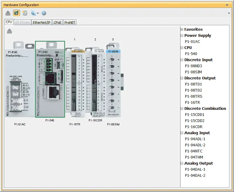
Double-clicking on the CPU module will bring up the CPU Module window. This has four tabs along the top; Options, Ethernet Port, Remote Access, Serial Ports. Configuration of the web server is done here.
Select the Ethernet Port tab.
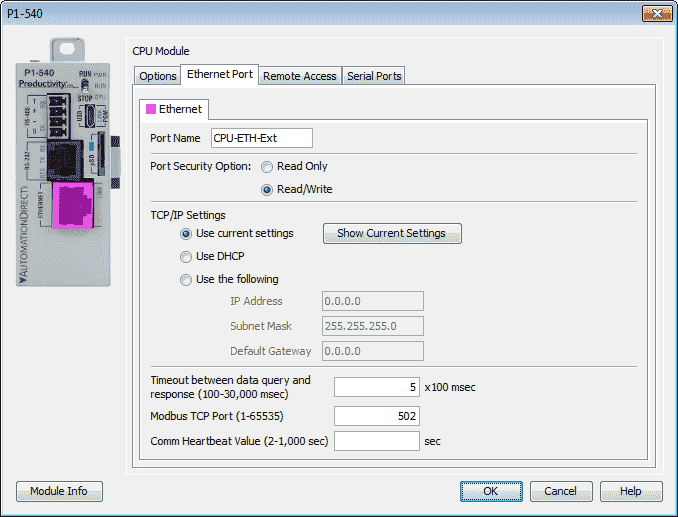
Under the TCP/IP Settings we want to set our addresses for the PLC. This will ensure that the settings will not be changed when accessing the web server. Select the Show Current Settings button.
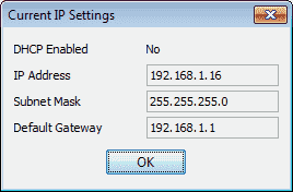
Note the settings and select OK.
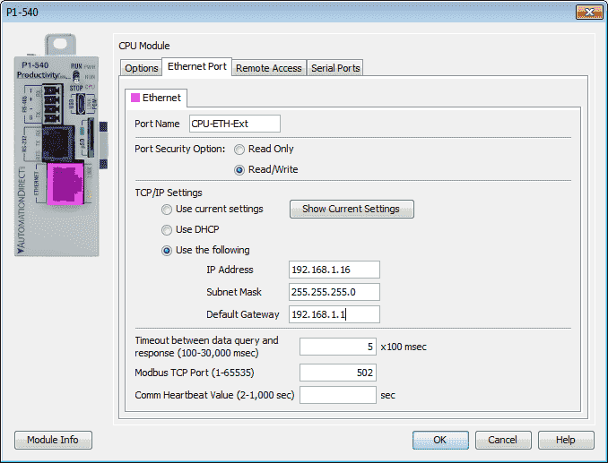
Select the Use the following radio button and enter the settings noted above.
Select the Remote Access tab.
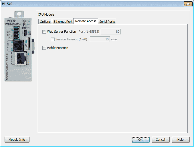
Select the Web Server Function box. We will leave the default port as 80. Port 80 is the port number assigned to commonly used internet communication protocol, Hypertext Transfer Protocol (HTTP).
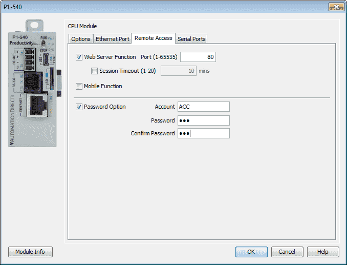
Note: If this was on a network, I would suggest turning on the Session Timeout. This will automatically log the user out after the set amount of minutes.
Select the Password Option. The account name in our example is ACC and the password is acc. Select OK once you have entered the information.
Since we have changed the configuration of the CPU, we perform a program transfer.
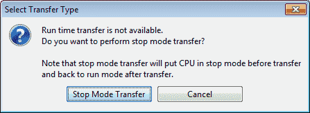
This is a stop mode transfer because our configuration change.
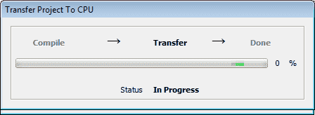
Once the information is transferred, the PLC can be put into run mode. Our web server should now be available through our browser.
Running the Productivity Web Server
Start your browser. In our case, this is Google chrome. Enter the IP address of the web server. (192.168.1.16)
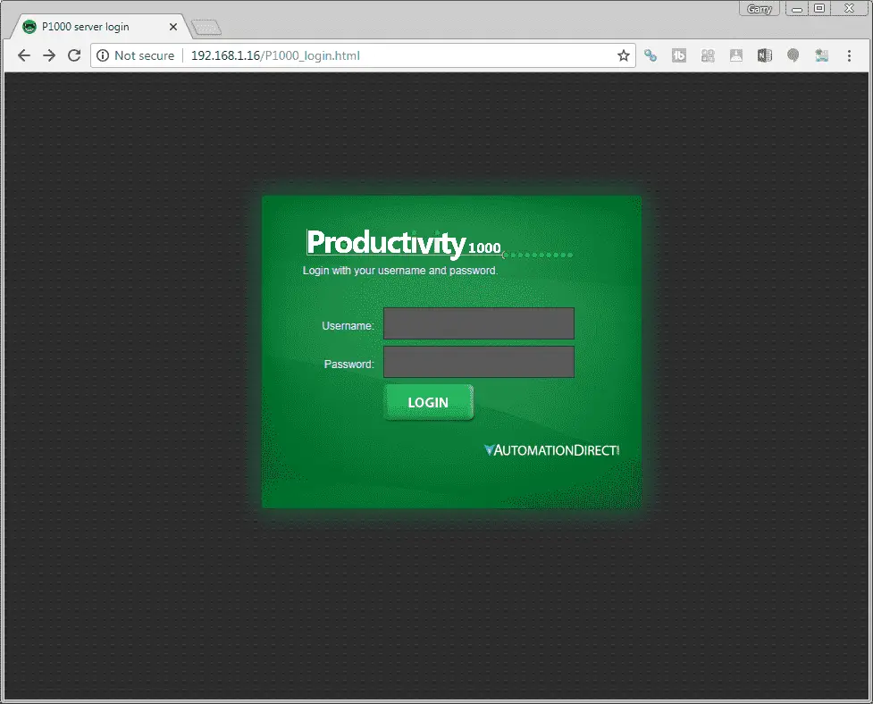
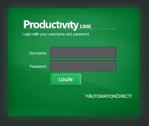
This should automatically show you the login screen.
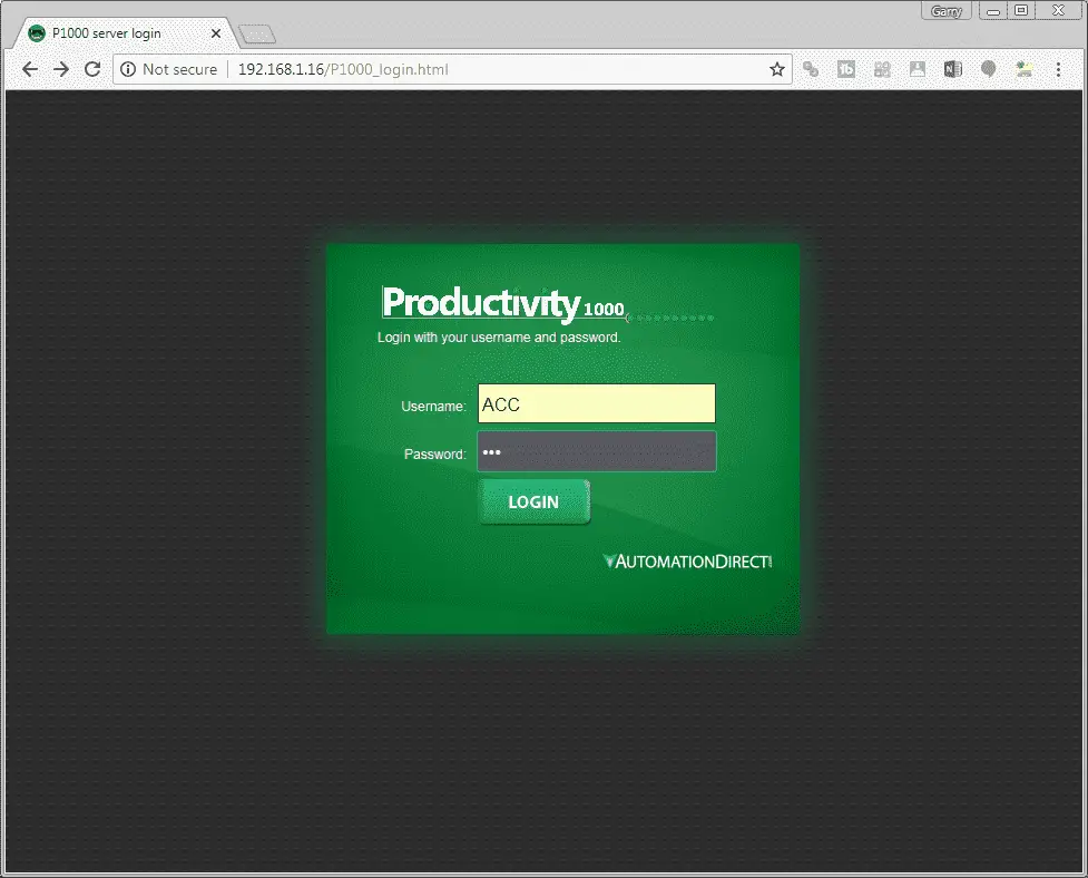
Enter the credentials that we configured for our example. (ACC – acc) Press the LOGIN button.
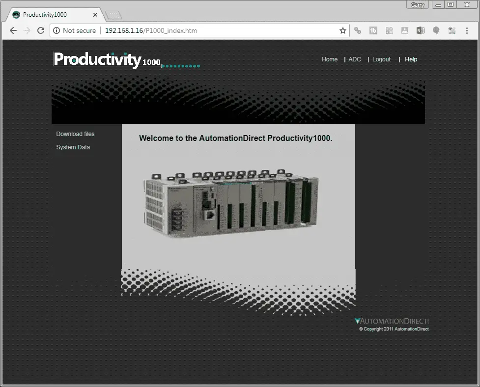
Home – This is the page that you see above.
ADC – This is a link that will open the Automation Direct website.
Logout – This will log you out of the web server.
Help – This is a link that will open the Productivity 1000 User Manual Online
Download Files – This will allow you to open, save or delete files on the micro SD card.
System Data – This is a read only of the system data in the PLC.
Download Files – Productivity Web Server
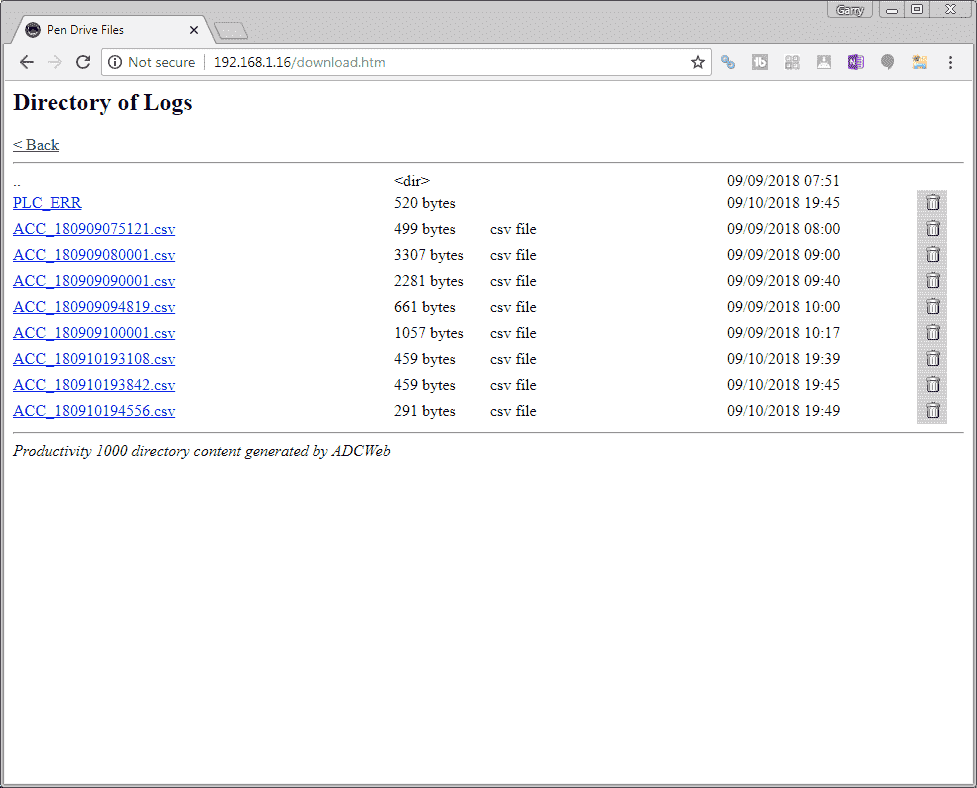
Selecting the download files will open the above web page. Here you can click on the file to download it to your computer. Once downloaded, you can call it up in notepad or excel to read the contents. The garbage can icon to the right of the file will delete the file off of the micro SD card.
The System Data – Productivity Web Server
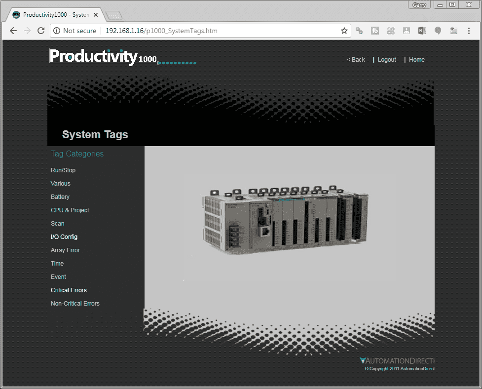
When the system data web page is displayed you can choose several of the read only memory information about the PLC.
Run/Stop – Current status of the PLC
Various – Forces, I/O Error, Watchdog Timeout, Portable Memory Device Ready, Portable memory device Eject
Battery – Information on the battery in the PLC
CPU & Project – Information on the CPU, Firmware, Current Program File Name, Program Memory Size, Ethernet Speeds
Scan – This will give you various information on the PLC scan
I/O Config – This will indicate if you have errors in the input, output configuration
Array Error – This will show errors associated with arrays.
Time – Current real time clock in the PLC.
Event – List of events in the PLC like STOP, RUN and New Programs Transferred.
Critical Errors – Current and previous critical errors that would stop the scan of the PLC.
Non-Critical Errors – Current and previous non-critical errors that would give an alarm on the PLC.
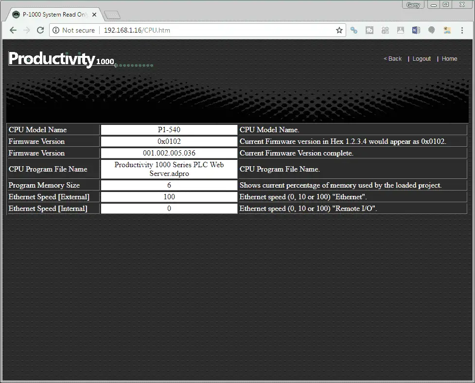
Here is an example of the CPU & Project web page information.
Download the PLC program here.
Watch the video below to see the running and configuration of the web server on our Productivity 1000 Series PLC.
Productivity 1000 Series PLC from Automation Direct
Overview Link (Additional Information on the Unit)
Configuration (Configure and purchase a system – BOM)
User Manual and Inserts (Installation and Setup Guides)
Productivity Suite Programming Software (Free Download Link)
This software contains all of the instruction sets and help files for the Productivity Series.
Next time we will look at serial Modbus RTU communication in the Productivity 1000 Series PLC.
Watch on YouTube: Productivity 1000 Series PLC Web Server
If you have any questions or need further information please contact me.
Thank you,
Garry
If you’re like most of my readers, you’re committed to learning about technology. Numbering systems used in PLC’s are not difficult to learn and understand. We will walk through the numbering systems used in PLCs. This includes Bits, Decimal, Hexadecimal, ASCII and Floating Point.
To get this free article, subscribe to my free email newsletter.
Use the information to inform other people how numbering systems work. Sign up now.
The ‘Robust Data Logging for Free’ eBook is also available as a free download. The link is included when you subscribe to ACC Automation.

