The EasyPLC machining center loading robots will demonstrate sequencing and robot control using a PLC. Two input lines feed blanks to the robot. The robot will alternate taking the blanks and putting them into the CNC (Computer Numerical Control) machine. The robot moves the piece to the finished conveyor when the part has been machined. A three-axis robot loader will pick up the part and place this in a storage box on the roller conveyor.
 Using the five steps for PLC program development, we will discuss and show you how to program this EasyPLC machining center. This will involve all the ladder logic to load and unload using the robot simulator. This PLC simulator will show sequencing and drum instruction programming using timers and events. An Automation Direct BRX Do-More PLC is used for this application, but the general methods can be used for just about any PLC on the market. Let’s get started.
Learn PLC programming the easy way. See below how to receive a 10% discount on this already cost-effective learning tool. Invest in yourself today.
Previously we have done the following:
Easy PLC Installing the Software – Video
EasyPLC Software Suite – Quick Start – Video
Click PLC – Easy Transfer Line Programming – Video
Productivity PLC Simulator – Chain Conveyor MS – Video
Do-More PLC – EasyPLC Box Selection Program – Video
Click PLC EasyPLC Gantry Simulator – Video
Click PLC Simple Conveyor EasyPLC – Video
EasyPLC Paint Line Bit Shift – BRX Do-More PLC – Video
Click PLC – EasyPLC PLC Mixer Programming – Video
Click PLC EasyPLC Warehouse Stacker Example – Video
– Operation Video
EasyPLC Machine Simulator Productivity PLC Robotic Cell – Video
EasyPLC Simulator Robotic Cell Click PLC – Video
EasyPLC Simulator Robotic Cell BRX Do-More PLC – Video
– EasyPLC Factory Editor Robotic Cell Additions Video
4 Way Traffic Light PLC Program EasyPLC – Video
Rock Crusher Plant EasyPLC BRX Do-More – Video
Freight Carrier Weighing and Distribution EasyPLC – Video
Define the task: (Step 1 – EasyPLC Machining Center Robot)
The first step of PLC program development is determining what must be done.
EasyPLC software suite contains this machining center robot example in the machine simulator. This is just one of many machines that come with the software so you can learn and develop your PLC programming skills.
The objective is to feed the machining center robot with blanks of the two input lines, managing the robot and CNC to make parts loading/unloading and machining. Then the parts worked must be sent to the output conveyor to be introduced into the storage boxes using the three-axis loader. (robot)
Start the EasyPLC Machine Simulator (MS). Select the start button on the main page or select machines from the main menu on the top of the machines simulator window.
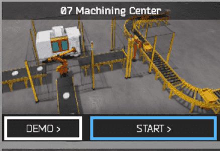
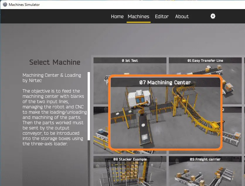 All the available machines will now be displayed. Click on the “07 Machining Center”.
This is the example that we will be programming. To the left of the screen, information will be displayed on how the freight carrier functions.
This is printed above.
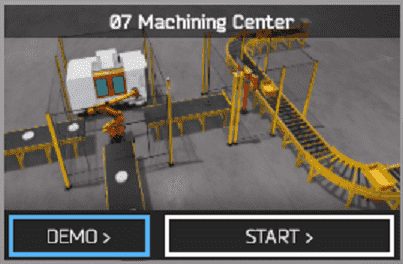 The machine simulator has a demo mode for the built-in machines. This will allow you to watch the operation of the freight carrier. Select the demo mode.
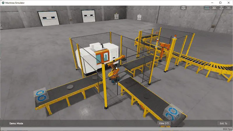 The EasyPLC machining center demo mode on the machine simulator will operate, showing you the basics of operation.
Move around the 3D virtual environment. Three icons on the top of the window will allow you to move around this 3D environment. The first icon is the default selection. This will enable you to move around without bumping into the components. The last icon will automatically show you around this virtual environment. The first-person mode will mimic a person in your 3D learning world. Once we understand what must be done, we can move on to the next step in our PLC program development.
Define the Inputs and Outputs: (Step 2 – EasyPLC Machining Center Robot)
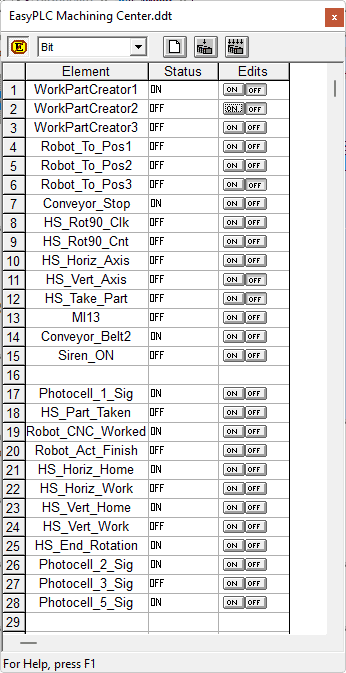
The View IO at the bottom of the machine simulator window will display the inputs and outputs required for this freight carrier example. While still in demo mode, you can see the operation of the inputs and outputs.
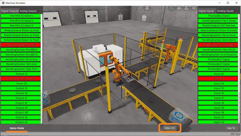 The EasyPLC machining center robot example will require 15 digital outputs and 12 digital inputs.
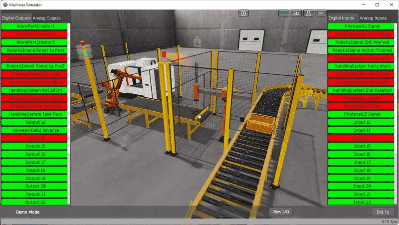 The EasyPLC start mode will allow you to control the machining center simulator manually.
 This is ideal if you are unsure what output or input is doing.
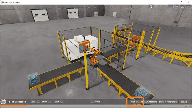 Select the View IO on the bottom middle of the machine simulator window. You can manually run the robotic cell without any control or PLC connected.
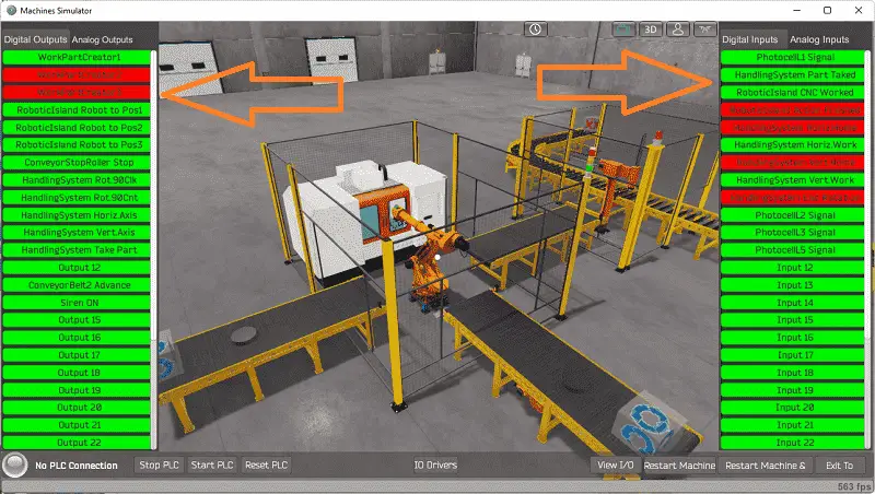 You can now use select and start the freight carrier digital outputs on the left side of the screen by clicking on them with the mouse. The right side will show you the corresponding digital inputs. The restart button on the bottom of the machine simulator window will reset the scene back to the start.
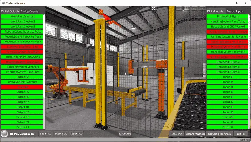 Move around the 3D environment and ensure you know what each input and output represents.
The following table will define the inputs and outputs (IO) and Modbus addresses in the BRX Do-More PLC we will use for this program.
| Digital Type | Description | BRX Do-More PLC Modbus Address | Machine Simulator Modbus Address |
| PLC Output – MS Input | Work Part Creator 1 – Storage Box | MI1 – 10001 | 0 |
| PLC Output – MS Input | Work Part Creator 2 – Conveyor 1 | MI2 – 10002 | 1 |
| PLC Output – MS Input | Work Part Creator 3 – Conveyor 3 | MI3 – 10003 | 2 |
| PLC Output – MS Input | Robot to Position 1 | MI4 – 10004 | 3 |
| PLC Output – MS Input | Robot to Position 2 | MI5 – 10005 | 4 |
| PLC Output – MS Input | Robot to Position 3 | MI6 – 10006 | 5 |
| PLC Output – MS Input | Conveyor Stop Roller | MI7 – 10007 | 6 |
| PLC Output – MS Input | Handling System Rotate 90 Clock Wise | MI8 – 10008 | 7 |
| PLC Output – MS Input | Handling System Rotate 90 Counter Clock Wise | MI9 – 10009 | 8 |
| PLC Output – MS Input | Handling System Horizontal Axis | MI10 – 10010 | 9 |
| PLC Output – MS Input | Handling System Vertical Axis | MI11 – 10011 | 10 |
| PLC Output – MS Input | Handling System Take Part | MI12 – 10012 | 11 |
| PLC Output – MS Input | Output 12 – Not Used | MI13 – 10013 | 12 |
| PLC Output – MS Input | Conveyor Belt 2 Advance | MI14 – 10014 | 13 |
| PLC Output – MS Input | Siren On – Three-Axis Robot | MI15 – 10015 | 14 |
| PLC Input – MS Output | Photocell 1 – Conveyor 1 | MC1 – 1 | 0 |
| PLC Input – MS Output | Handling System Part Taken | MC2 – 2 | 1 |
| PLC Input – MS Output | CNC Work Complete | MC3 – 3 | 2 |
| PLC Input – MS Output | Robot Action Finished | MC4 – 4 | 3 |
| PLC Input – MS Output | Handling System Horizontal Home | MC5 – 5 | 4 |
| PLC Input – MS Output | Handling System Horizontal Work | MC6 – 6 | 5 |
| PLC Input – MS Output | Handling System Vertical Home | MC7 – 7 | 6 |
| PLC Input – MS Output | Handling System Vertical Work | MC8 – 8 | 7 |
| PLC Input – MS Output | Handling System End Rotation | MC9 – 9 | 8 |
| PLC Input – MS Output | Photocell 2 – Conveyor 3 | MC10 – 10 | 9 |
| PLC Input – MS Output | Photocell 3 – Conveyor 2 | MC11 – 11 | 10 |
| PLC Input – MS Output | Photocell 5 – Storage Box Conveyor | MC12 – 12 | 11 |
Note: The machine simulator will be offset by one on the Modbus Addresses. See the video below for the demo mode and determining inputs and outputs.
See the video below for the demo mode and determining inputs and outputs.
Develop a logical sequence of operation: (Step 3 – EasyPLC Machining Center Robot)
A PLC programmer must know how everything about the sequence and operation of the machine before programming. The machining center robot is an excellent way to learn to program. A flow chart or sequence table is used to understand the process that needs to be controlled thoroughly. It must also answer questions like the following:
What happens when electrical power or pneumatic air is lost? What happens when the input/output devices fail? Do we need redundancy?
This step is where you will spend most of your time. Understanding everything about the operation will save you time. It will help prevent you from continuously re-writing the PLC program logic. Knowing all these answers to how the system is to react is vital in developing the PLC program.
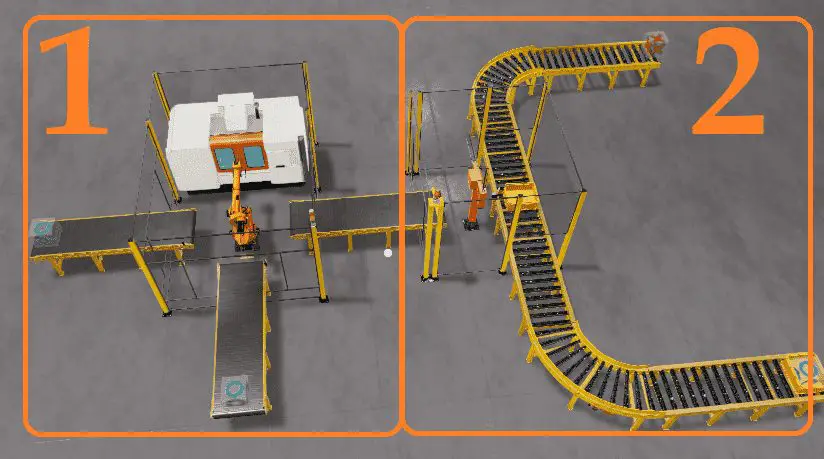
Our EasyPLC machining center machine is split up into two different sections. We will walk through the logical sequence of operation.
 Splitting the requirements up into smaller sections will allow you to concentrate on the task and not get distracted by other parts of the program that are unrelated.
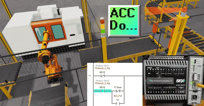
Section 1 of the logic will alternate taking blanks off of conveyors 1 and 3. The robot to position one will take a blank part off conveyor one and place it into the CNC machine. The robot to position three will take a blank part off conveyor three and put it into the CNC machine. Once the CNC worked input turns on, the activating robot to position two will remove the finished part and place it on conveyor 2.
Section 2 of the logic will ensure a storage box in front of photocell 5. This will happen when part creator one is turned on. The storage box will stop due to the conveyor stop roller that will be set. Once the storage box is in position and a machined part is at the end of the conveyor belt, the three-axis robot can transfer the part.
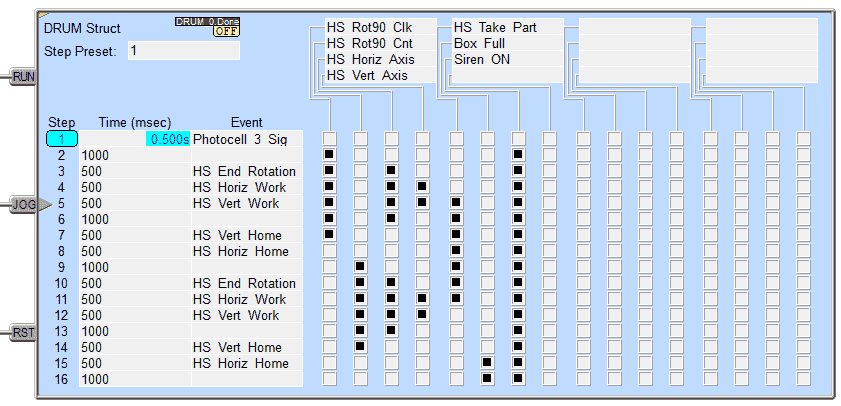 We will use a DRUM instruction in the PLC to control the three-axis robot. As you can see, this is just a matter of filling in the inputs and timing for the sequence. The outputs are controlled individually by selecting them at each of the steps. The PLC’s drum instructions (sequencing) make this a straightforward step. We set an internal bit (C1) when the box has a machined product. This can then trigger the box to move along the conveyor.
A PLC programmer must know how everything about the sequence and operation of the machine before programming.
Ask questions or View existing documentation to ensure that you know the logical steps to the machine operation. Writing out what is supposed to happen will help to clarify what is required in the PLC program. This is just another method like flow charts and sequence tables.
Develop the BRX Do-More PLC program: (Step 4 – EasyPLC Machining Center Robot)
Using the information from the previous step, we can now program our BRX Do-More PLC. The BRX Do-More PLC Series will take you through installing the program, communicating to the controller instructions, and addressing the controller.
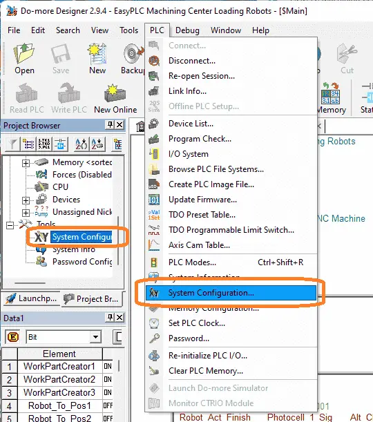 Select the system configuration under PLC on the main menu. You can also call this up by selecting system configuration under the tools menu in the project browser window.
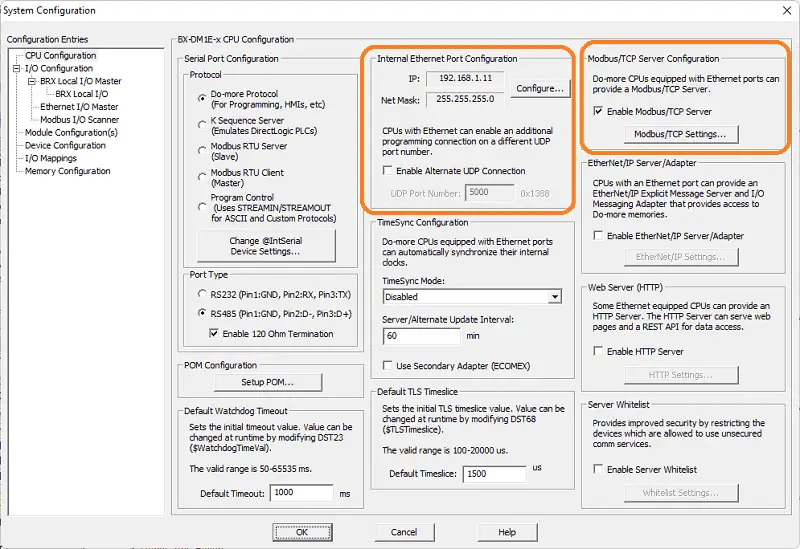 Select the configure button under the internal Ethernet port configuration.
 We will use a static IP address for the Ethernet port. Here are our settings for the Ethernet port. Select OK.
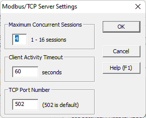 In the system configuration window, select Modbus TCP settings and ensure that the enable Modbus / TCP Server is set. This is on by default, with port 502 as the default number. Everything is left as the default. We can change some of these settings if communication can not be established reliably. Our PLC is now a Modbus TCP Server to the EasyPLC Modbus TCP Client. Please make a note of the static IP address that we are using for the BRX Do-More PLC. This will be used later to connect to the EasyPLC machine simulator.
Ladder Logic Program – Section 1
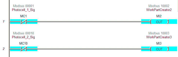 The first two rungs of the program will allow the parts to be created on conveyors 1 and 3. The pieces are made if the photocells do not see any product.
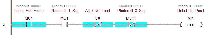 This rung will control loading the CNC with the robot from position 1. You will see the internal bit C0. This will be used to alternate between the two loading conveyors.
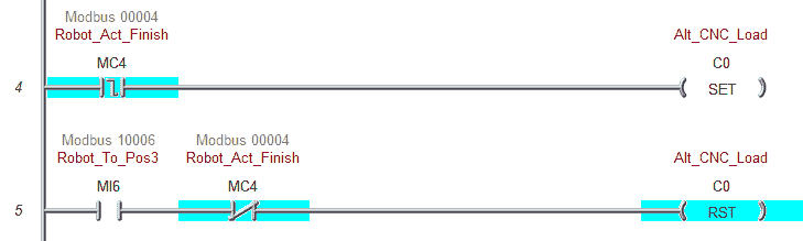 These two rungs will control C0 and the selection of the robot to conveyors 1 and 3.
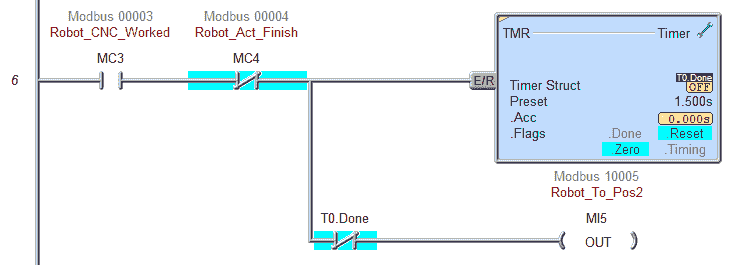 Robot position two will be controlled when the CNC work is done. A timer is used so that a pulse is given to the robot to unload the machine part.
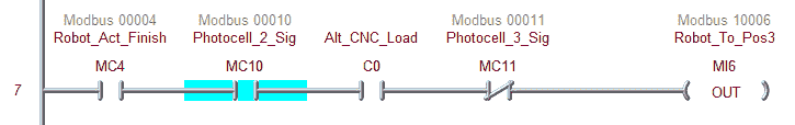 This rung will control the robot position 3. It will load the blank from conveyor three and put it in the CNC machine.
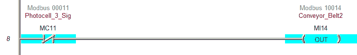 If the finished conveyor does not have a part, then the conveyor will operate.
This is the end of section 1. You can save, download and try the operation to ensure that this section works correctly. Once it is, you can move on to the next area of the program.
Section 2 – Three-Axis Robot
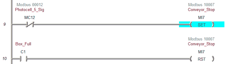 These rungs will control the conveyor stop. It will be on when there is no signal from the photocell and off when the storage box contains a machined part.
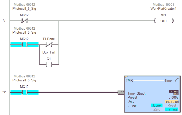 The storage box is created when there is no box at the photocell or when the box is full. A timer ensures that the storage box is flush with the conveyor stopper. You will see it straighten itself up during this time.
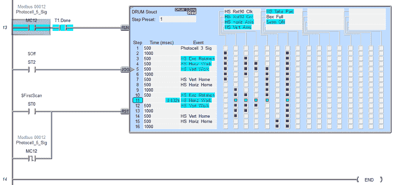 A Drum instruction is used to sequence the three-axis. The drum sequence will reset on the PLC’s first scan or the photocell’s trailing edge. It will run when a storage box is present on the conveyor.
Our ladder logic program is complete. Download the program to the BRX D0-More PLC. Ensure that the controller is in run mode.
Watch the video below to see this BRX Do-More PLC program in action
Test the program: (Step 5 – EasyPLC Machining Center Robot)
We will use Modbus TCP on our BRX D0-More PLC to communicate to the EasyPLC Machine Simulator.
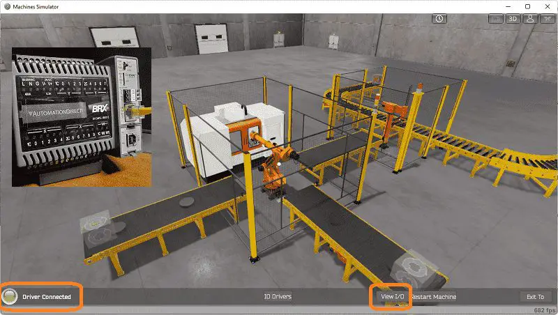
Call up the machining center in start mode.
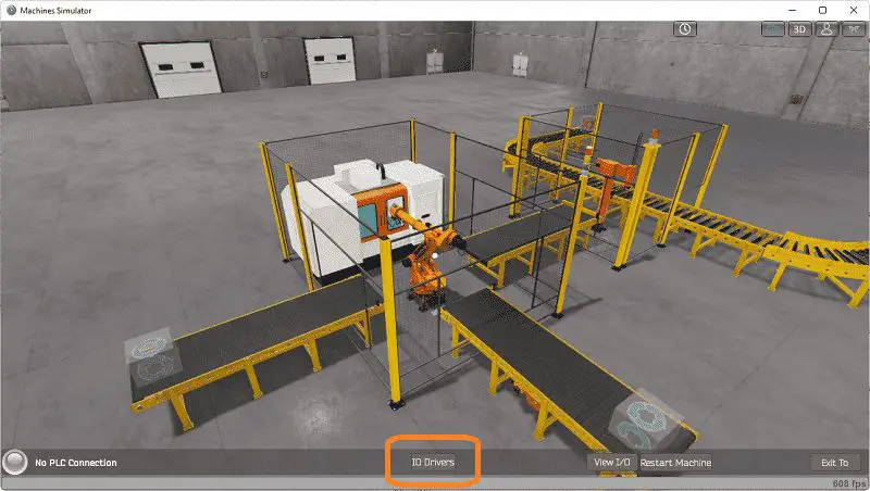 The status of the machine simulator will be along the bottom of the screen. Currently, we have no PLC connected. Select IO Drivers on the bottom middle of the screen.
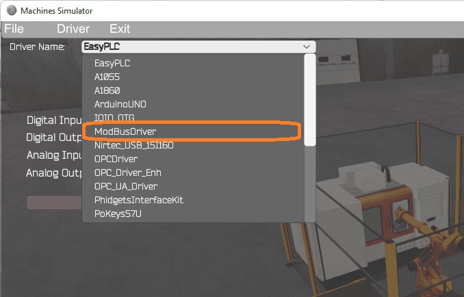 The EasyPLC driver is selected by default. Under the driver pull-down menu, select “ModBusDriver.” This driver will communicate Modbus TCP (Ethernet) and Modbus RTU (Serial). Select the down arrow on the driver’s name.
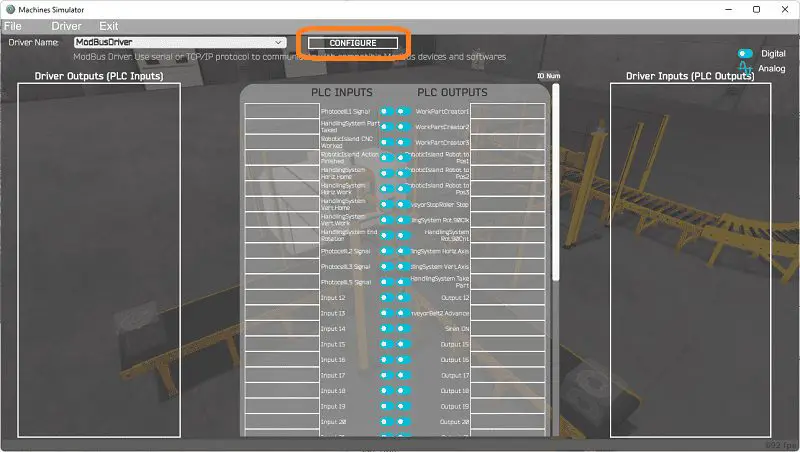 Select the configure button.
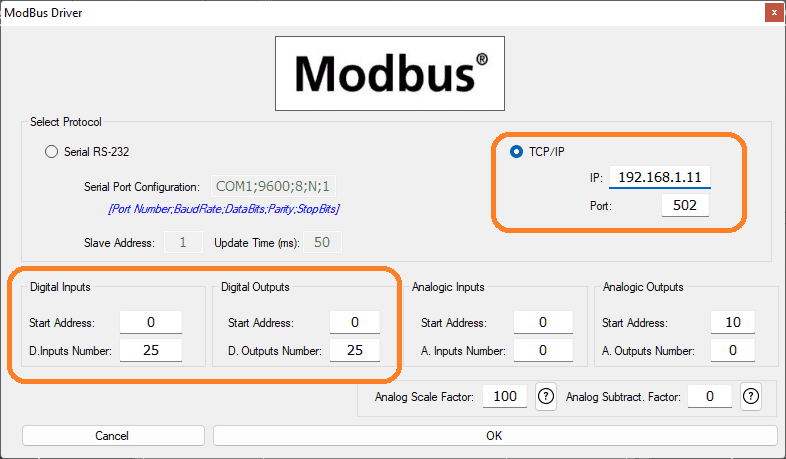 We can now enter the information for our Modbus driver. Select TCP/IP. This means the Ethernet port on the computer will communicate to the PLC.
The digital inputs from MS to the BRX Do-More PLC will be MC1 to MC12. This will start at address 0 due to the offset of 1, and the first input is not used. Digital outputs from MS to the BRX Do-More PLC will be MI1 to MI15. This will start at address one due to the offset of 1, and the first input is not used. Select the OK button.
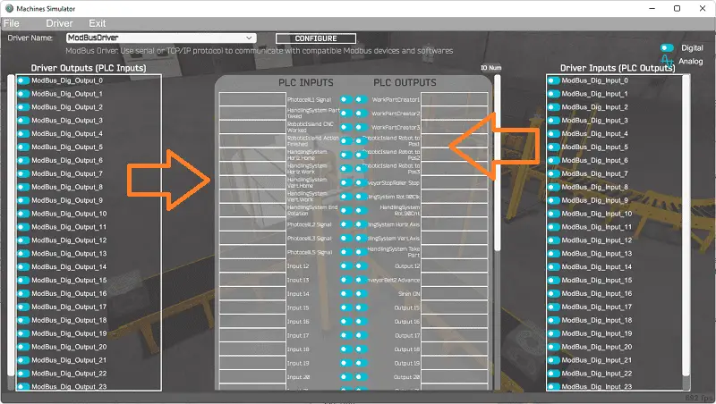 You will now see the inputs and outputs specified for the Modbus driver. We can manually assign the driver outputs to the PLC inputs and the driver inputs to the PLC outputs. However, the automatic assignment works well and will save you time.
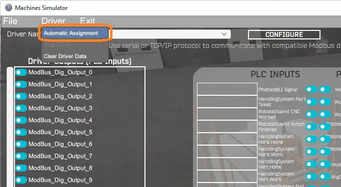 Select Automatic Assignment from the driver option in the main menu.
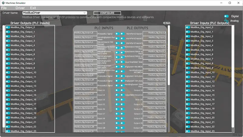 This will automatically assign the PLC IO to the Machine Simulator IO.
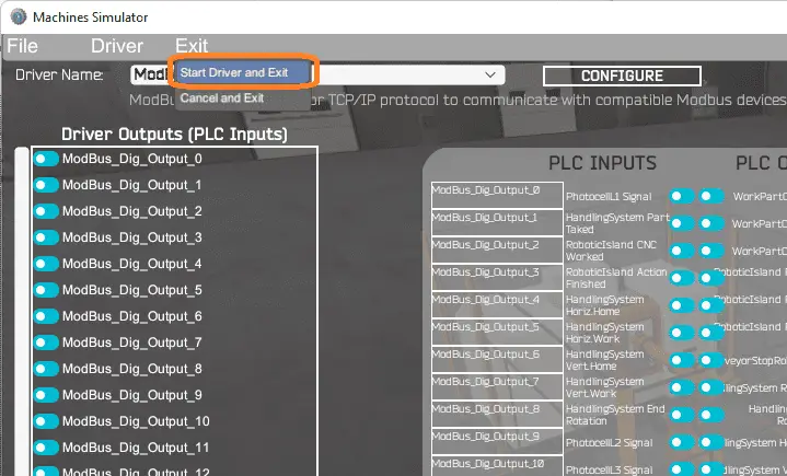 Select start driver and exit from the main menu.
 On the bottom left side of the window, you will see that the driver communicates to the PLC by the green light. Select view IO to know the input and output status of the machine simulator.
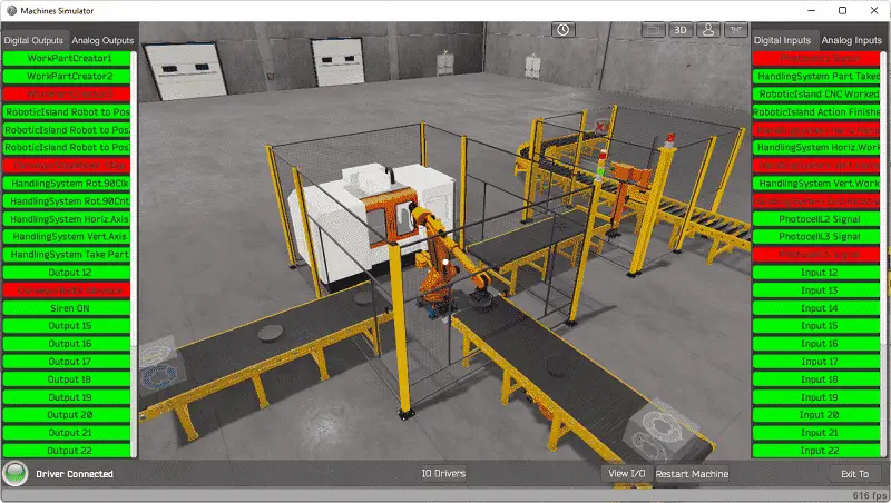 Ensure that the PLC is in run mode. We can see the operation of our EasyPLC machining center robot.
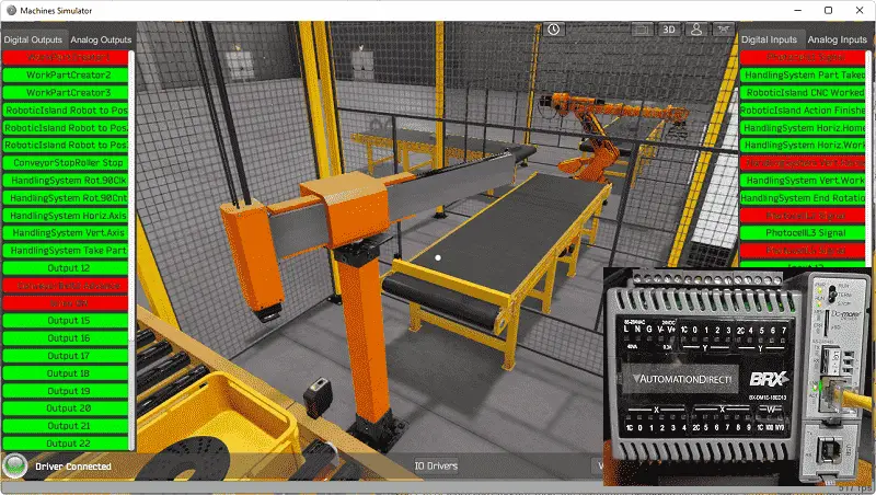
 Using the Data View window of the Do-More Designer programming software, we can also watch the inputs and output operations.
Watch the video below to see this operation.
If your program works correctly, it’s time to move on. If not, you’ll need to debug. This can be as simple as re-downloading and re-uploading your program or as complicated as redesigning your logic altogether. When using EasyPLC, debugging is quickly done with no damage to any equipment. You may modify your logic several times before you get everything right! That’s okay—it’s all part of learning. After all: trial and error are often easier said than done! To learn more about developing logic, check out our tutorials on the five steps to PLC program development.
You can practice your modification and debug by modifying the machining center in the following way:
– Change the times and make the drum instruction work faster
– Put in a control panel with a stop, start and jog circuit for the three-axis robot.
Let me know how you make out in the comments below.
Download the BRX Do-More PLC sample program here.
Watch the video below to see the five steps of program development applied to the machining center robot. The machine simulator is one of the best applications to help you learn PLC programming.
EasyPLC Software Suite is a complete PLC, HMI, and Machine Simulator Software package. This PLC learning package includes the following:
Easy PLC – PLC Simulation allows programming in Ladder, Grafcet, Logic Blocks, or Script.
HMI System – Easily create a visual human-machine interface (HMI)
Machine Simulator – A virtual 3D world with real-time graphics and physical properties. PLC programs can be tested using the EasyPLC or through other interfaces. (Modbus RTU, TCP, etc.)
Machine Simulator Lite – Designed to run on Android Devices.
Machine Simulator VR – Virtual Reality comes to life so you can test, train or practice your PLC programming.
Purchase your copy of this learning package for less than USD 75 for a single computer install or less than USD 100 to allow different computers.
Receive 10% off the price by typing in ACC in the comment section when you order. http://www.nirtec.com/index.php/purchase-price/
Learn PLC programming the easy way. Invest in yourself today.
Watch on YouTube: EasyPLC Machining Center Loading Robots
If you have any questions or need further information, please contact me.
Thank you,
Garry
If you’re like most of my readers, you’re committed to learning about technology. Numbering systems used in PLCs are not challenging to learn and understand. We will walk through the numbering systems used in PLCs. This includes Bits, Decimal, Hexadecimal, ASCII, and Floating Point.
To get this free article, subscribe to my free email newsletter.
Use the information to inform other people how numbering systems work. Sign up now.

The ‘Robust Data Logging for Free’ eBook is also available for free download. The link is included when you subscribe to ACC Automation.