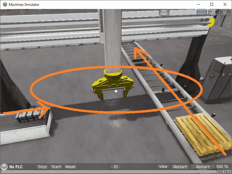
The Machine Simulator (MS) is part of the EasyPLC software suite. It has many built-in machines that can be programmed. The gantry loader is one of these machines. It will pick up metal boxes from a conveyor and place two on a wooden pallet. The Click PLC will be used to program this virtual machine.
 Using the Click Plus PLC, we will connect the simulator to the gantry loader machine. This will be done using Modbus TCP (Ethernet) for communications. Using the five steps for program development we will show how this is programmed. The logical sequence step will include a flow chart and a sequence of operations. The sequence of operations will be done using indirect addressing in the Click PLC. Let’s get started.
The Machine Simulator (MS) is part of the EasyPLC Software Suite. This is a complete PLC, HMI, and Machine Simulator Software package. This PLC learning package includes a Machine Simulator (MS). This virtual 3D world with real-time graphics and physical properties can communicate to several different programmable logic controllers. (PLC) See below to receive a 10% discount off of this PLC learning package. Invest in yourself today.
Previously we have done the following:
Easy PLC Installing the Software – Video
Click PLC – Easy Transfer Line Programming – Video
Productivity PLC Simulator – Chain Conveyor MS – Video
Do-More PLC – EasyPLC Box Selection Program – Video
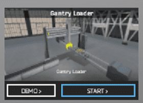
Define the task: (Step 1 – Click Gantry Loader)
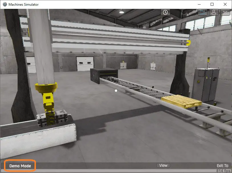
The machine simulator has a demo mode for the built-in machines. This will allow you to watch the operation of the gantry loader. This will help you see what has to be done.
 There is also a written version of the sequence on the left-hand side of the machine.
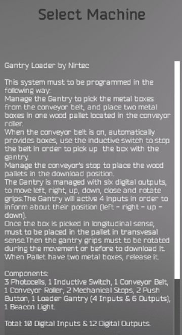 Manage the gantry to pick the metal boxes from the conveyor belt and place two metal boxes on one wood pallet. The wood pallet is located in the conveyor roller. When the conveyor belt is on it will provide boxes. Use the inductive switch to stop the belt in order to pick up the box with the gantry. Manage the conveyors stop to place the wood pallets in the download position.
The gantry is operated with six digital outputs to move left, right, up, down, close, and rotate. 4 inputs are used to inform you of the gantry position. (Left, right, up, and down)
Once the box is picked up in the longitudinal sense, it must be placed on the pallet in the transversal sense. So the gantry grips must be rotated during the movement or before to place on the pallet. When the pallet has two metal boxes it can be released.
 Watch the sequence of operations in the video below.
Define the Inputs and Outputs: (Step 2 – Click Gantry Loader)
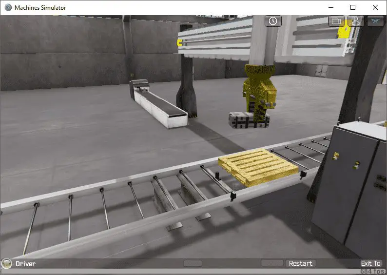
Start the gantry loader in start mode.
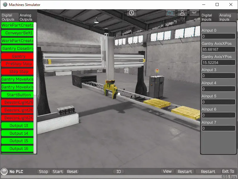
 The gantry loader simulator will load. Status is shown on the bottom and controls for the time frame and viewing area control on the top left of the window.
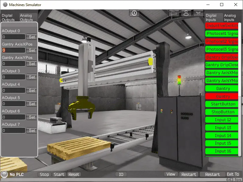
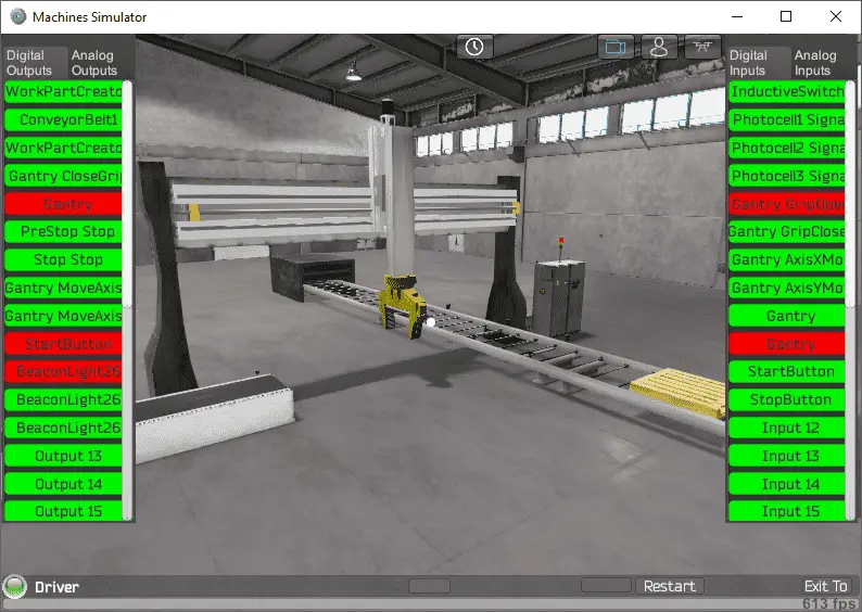
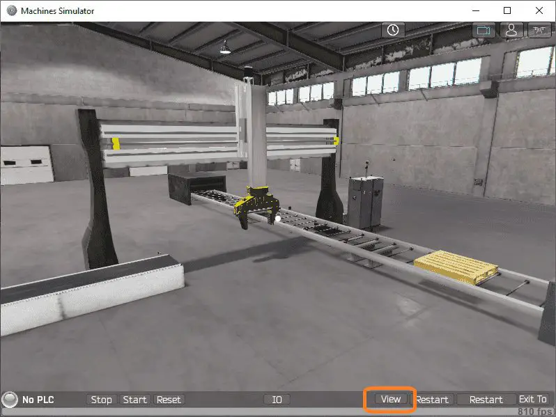 Select the View IO to display the inputs and outputs required for this machine. The digital IO is displayed as default.
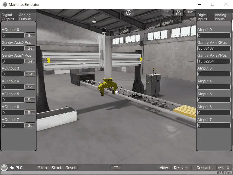
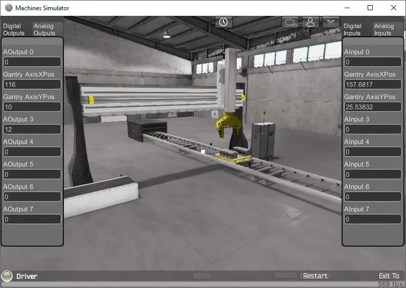
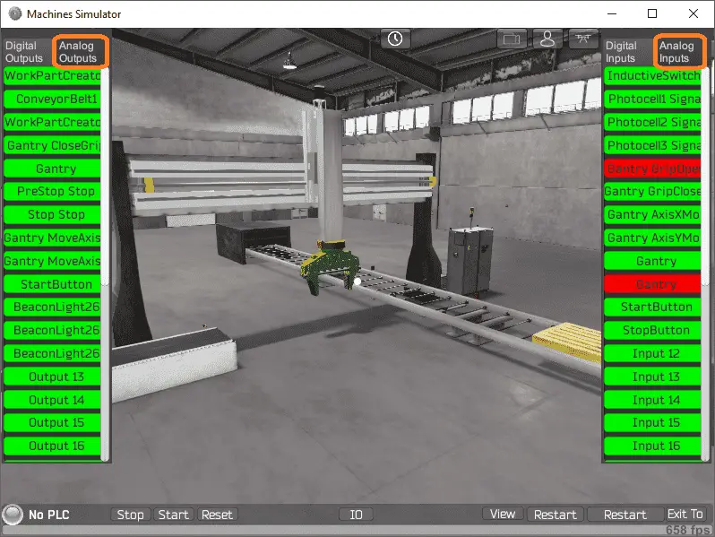 Select the analog outputs to view them.
 The gantry loader will require 12 digital outputs and 10 digital inputs. It will also require 2 analogs in and out. This will set the positions for the X and Y axis on the gantry.
Clicking on the digital outputs will activate it. Spend some time to fully understand the IO (inputs and outputs) functions.
 You can move around in the 3D environment and see the IO and items at different angles.
 The following table will define the inputs and outputs (IO) and Modbus addresses in the Click Plus PLC that we will use for this program.
| Digital Type | Description | Click PLC Modbus Address | Machine Simulator Modbus Address |
| PLC Output – MS Input | WorkPartCreator_Pallet | 8225 – Y101 | 8224 |
| PLC Output – MS Input | ConveyorBelt1 Start | 8226 – Y102 | 8225 |
| PLC Output – MS Input | WorkPartCreator_Box | 8227 – Y103 | 8226 |
| PLC Output – MS Input | Gantry Close Grip | 8228 – Y104 | 8227 |
| PLC Output – MS Input | Gantry Rotate Grip | 8229 – Y105 | 8228 |
| PLC Output – MS Input | PreStop Stop | 8230 – Y106 | 8229 |
| PLC Output – MS Input | Stop Stop | 8231 – Y107 | 8230 |
| PLC Output – MS Input | Gantry Move Axis X | 8232 – Y108 | 8231 |
| PLC Output – MS Input | Gantry Move Axis Y | 8233 – Y109 | 8232 |
| PLC Output – MS Input | Start Button Flashing | 8234 – Y110 | 8233 |
| PLC Output – MS Input | BeaconLight26 Red Light | 8235 – Y111 | 8234 |
| PLC Output – MS Input | BeaconLight26 Yellow | 8236 – Y112 | 8235 |
| PLC Output – MS Input | BeaconLight26 Green | 8237- Y113 | 8236 |
| Analog PLC Output – MS Input | Gantry Axis X Set Pos | 400101 – DS101 | 100 |
| Analog PLC Output – MS Input | Gantry Axis Y Set Pos | 400102 – DS102 | 101 |
| PLC Input – MS Output | Inductive Switch1 Signal | 100033 – X101 | 32 |
| PLC Input – MS Output | Photocell 1 Signal | 100034 – X102 | 33 |
| PLC Input – MS Output | Photocell 2 Signal | 100035 – X103 | 34 |
| PLC Input – MS Output | Photocell 3 Signal | 100036 – X104 | 35 |
| PLC Input – MS Output | Gantry Grip Open | 100037 – X105 | 36 |
| PLC Input – MS Output | Gantry Grip Close | 100038 – X106 | 37 |
| PLC Input – MS Output | Gantry Axis X Moving | 100039 – X107 | 38 |
| PLC Input – MS Output | Gantry Axis Y Moving | 100040 – X108 | 39 |
| PLC Input – MS Output | Gantry Part Detect | 100041 – X109 | 40 |
| PLC Input – MS Output | Gantry Stop Rotate | 100042 – X110 | 41 |
| PLC Input – MS Output | Start Button | 100043 – X111 | 42 |
| PLC Input – MS Output | Stop Button | 100044 – X112 | 43 |
| Analog PLC Input – MS Output | Gantry Axis X Position | 400111 – DS111 | 109 |
| Analog PLC Input – MS Output | Gantry Axis Y Position | 400112 – DS112 | 110 |
Note: The machine simulator will be offset by one on the Modbus Addresses.
When communicating to the machine simulator using Modbus, the real numbers used in the X and Y-Axis will not work. The scaling can be changed for positioning to be a 16-bit positive number only. The script code for the Gantry component can be downloaded below.
Place this in the following location:
C:\Nirtec\Machines Simulator 3\ms3bin_Data\UserDefinedComponents\GantryTwoAxis.udc
The X axis will go from 0 (left) to 140 (right) and the Y-axis from 12 (up) to 0 (down).
Develop a logical sequence of operation: (Step 3 – Click Gantry Loader)
A flow chart or sequence table is used to fully understand the process the needs to be controlled. It must also answer questions like the following:
What happens when electrical power and/or pneumatic air is lost? What happens when the input/output devices fail? Do we need redundancy?
This step is where you can save yourself a lot of work by understanding everything about the operation. It will help prevent you from continuously re-writing the PLC program logic. Knowing all of these answers upfront is vital in the development of the PLC program.
Our Click PLC Gantry Loader can be seen as three different operations. Box Conveyor, Pallet Conveyor, and Gantry Operation.
A conveyor for the box will produce a box and have it present at the end of the conveyor for the gantry to pick up and place on the pallet.
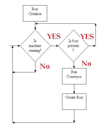 Here is a simple flow chart on how this is achieved for the box conveyor.
The pallet conveyor will stop the pallet using a stopper. Once the gantry places two boxes on the pallet the pallet will be released and another pallet will be placed in the fill position.
The Gantry will move the X and Y axis to pick up and place two boxes, one at a time on the pallet.
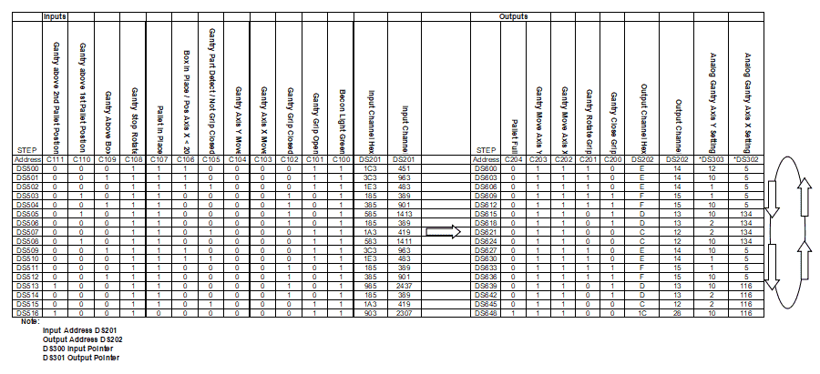 Here is a sequence table for the Gantry. If the inputs are correct then the corresponding outputs are set. This includes the X and Y-axis positions for the Gantry. Using a sequence table for the gantry will help you to fully understand the operation of the Gantry Loader.
A PLC programmer must know how everything about the sequence and operation of the machine before programming.
Spend your time with this step of PLC programming. Understanding the entire sequence of operations, prior to writing and testing your program will save you a lot of work and time.
Develop the PLC program: (Step 4 – Click Gantry Loader)
Writing the Click PLC ladder logic code for the Gantry Loader PLC example will be the next step in our program development.
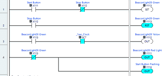 Here is the PLC code for the operation of the lights and controls.
The start pushbutton light will flash when the machine is ready to start. The red beacon light will be lit. When the start pushbutton is selected the red beacon is turned off and the green is lit. Flashing yellow beacon light is used to warn operators in the area that the machine is running.
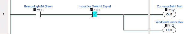 Next, we have the Click ladder logic for the box position at the end of the conveyor. This logic can be compared to the flow chart listed above.
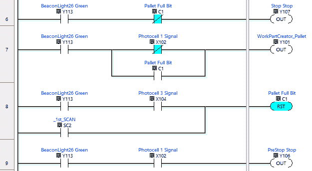 Here is the pallet operation in our Click PLC. This will control the conveyor and pallet positions.
 Our gantry input is now programmed. This has all of the input conditions that must be met in order for the gantry sequence to operate.
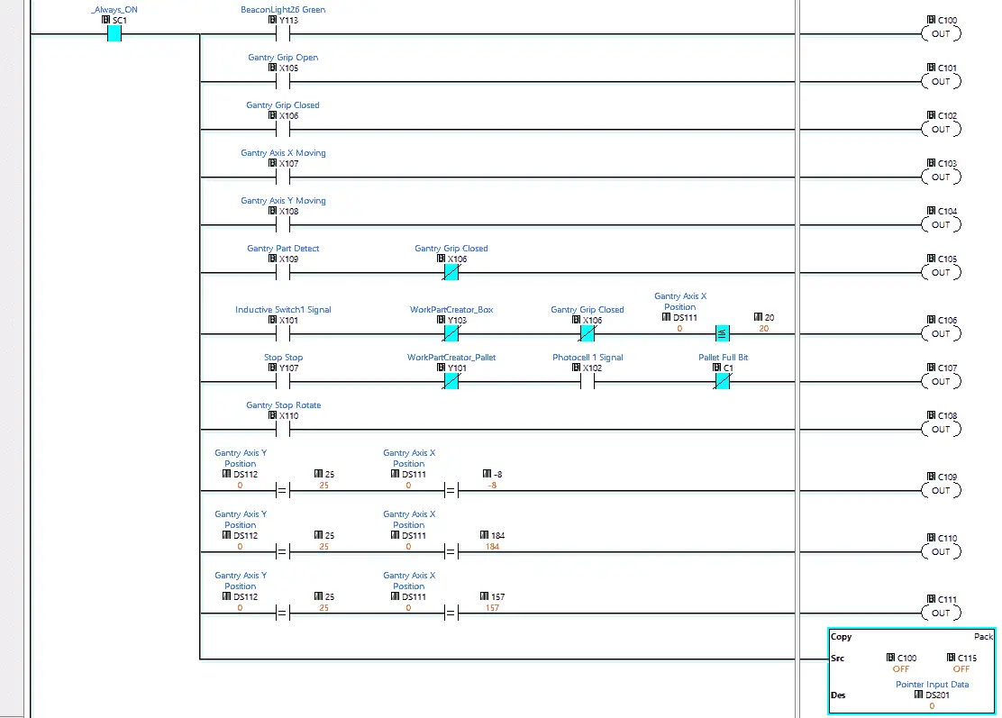
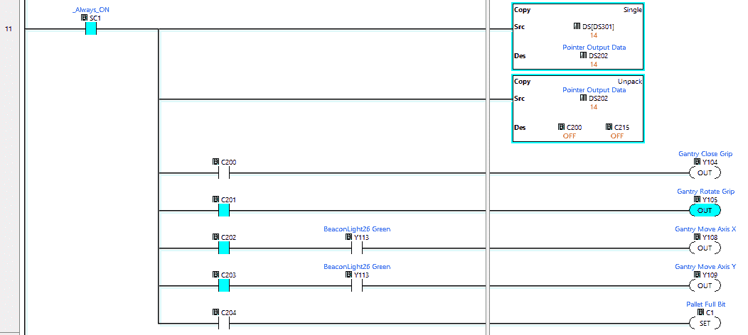 Our gantry output is now programmed. These are the output signals that will control the gantry sequencing.
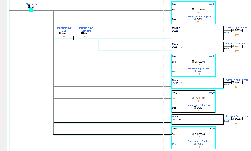 Indirect addressing (Pointers) in the Click PLC are used with the copy instruction. We compare the physical inputs to the sequence table and then set the outputs, X-Axis, and Y-Axis for the next step.
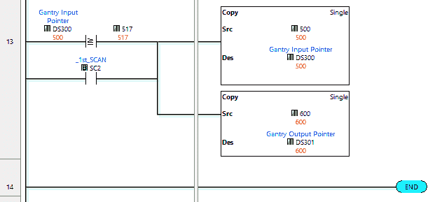 Our final rungs will initialize the sequencer in the Click PLC. This will happen upon power-up (first scan) of the PLC or when the end of the sequence has occurred.
See below to download the Click PLC program. Also, watch the video below for an explanation of the Gantry program.
Test the program: (Step 5 – Click Gantry Loader)
We will be using Modbus TCP on our Click PLC to communicate to the machine simulator.
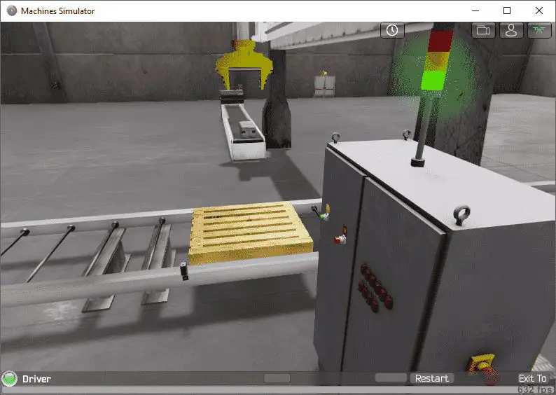
Call up the Gantry Loader in start mode.
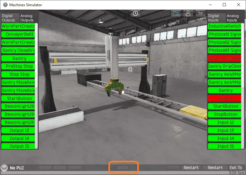 The status of the machine simulator will be along the bottom of the screen. Currently, we have no PLC connected. Select IO on the bottom middle of the screen.
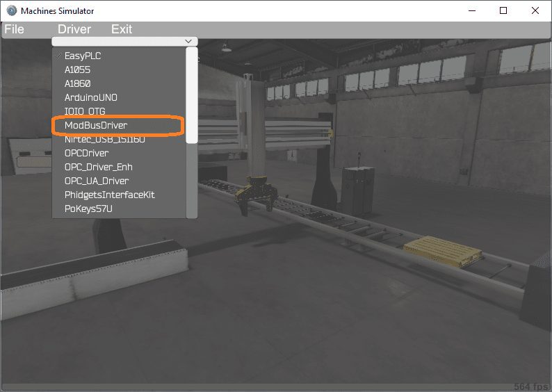 Under the driver pull-down menu, select “ModBusDriver”.
 This driver will communicate Modbus TCP (Ethernet) and Modbus RTU (Serial).
Select the configure button.
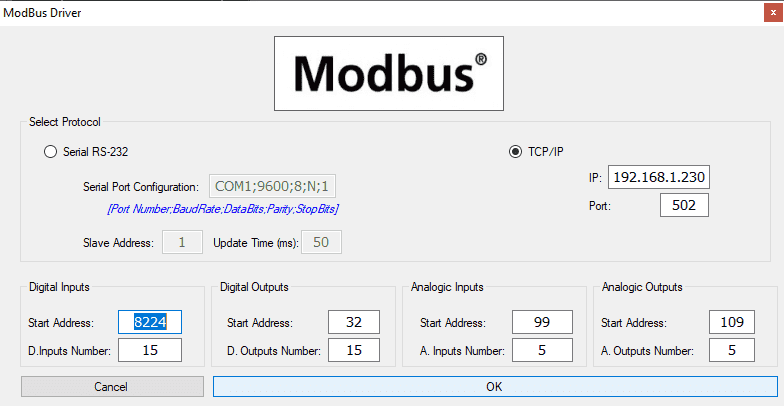 We can now enter the information for our Modbus driver. Select TCP/IP. This really means the Ethernet port on the computer that will communicate to the PLC.
The digital inputs from MS to the Click PLC will be Y101 to Y115. This will start at address 8224 due to the offset of 1. Digital outputs from MS to the Click PLC will be X101 to X115. This will start at address 32 due to the offset of 1.
Analog inputs from MS to the Click PLC will start at DS100 to DS105. This will start at address 99. MS to the Click PLC Analog outputs will be DS110 to DS115. The starting address will be 109 due to the offset of 1.
Select the OK button.
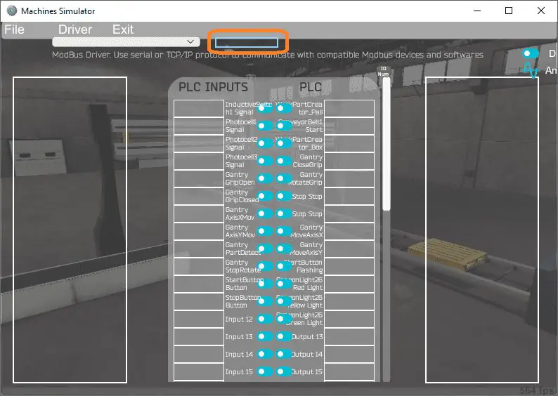
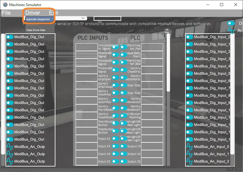 You will now see the inputs and outputs that we have specified for the Modbus driver. We can now manually assign the driver outputs to the PLC inputs and the driver inputs to the PLC outputs.
Select Automatic Assignment from the driver option in the main menu. This will automatically assign the PLC IO to the Machine Simulator IO.
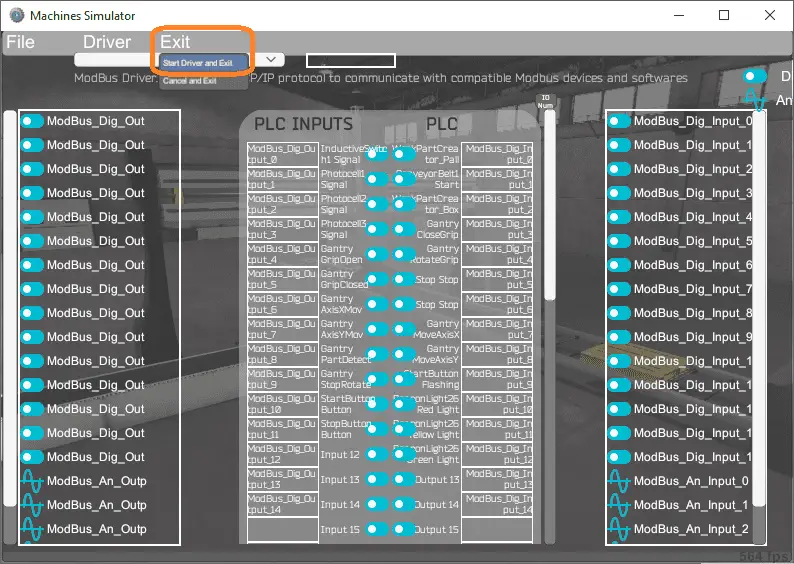 Select start driver and exit from the main menu.
 You will see on the bottom left side of the window that the driver is operating. Select view IO to see the input and output status of the machine simulator.
Ensure that the Click PLC is in run mode. We can now operate the Gantry machine simulator through the control panel.
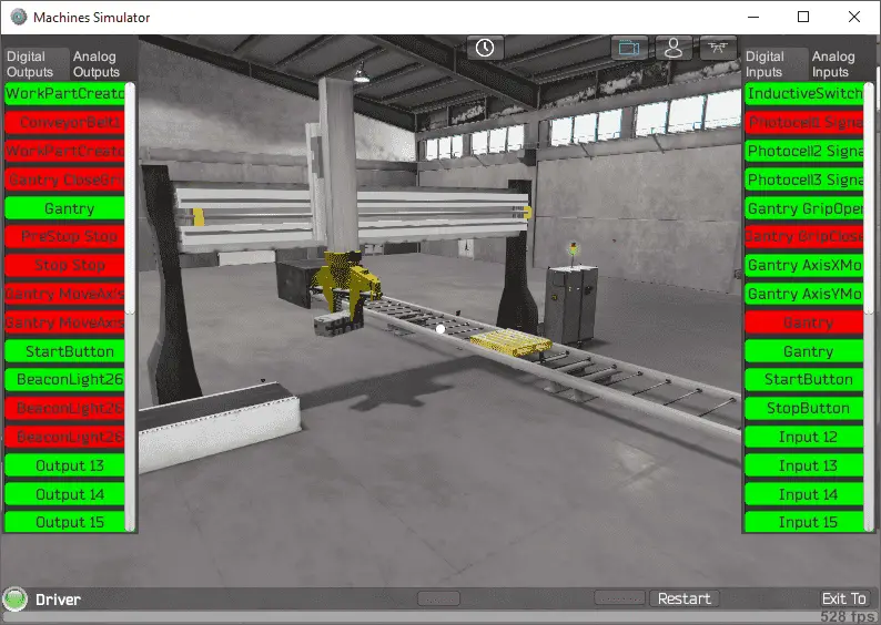
 Move around the EasyPLC Machine Simulator to view the machine operation at different angles.
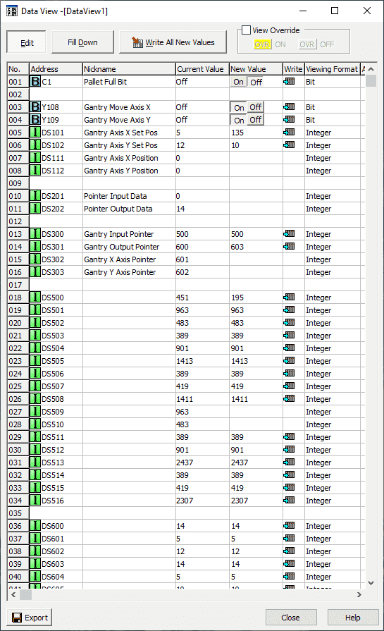
 Using the Data View window of the Click programming software we can also watch the inputs and output operations.
 Using Machine Simulator (MS) to test the program will ensure that our program works.
Watch the video below to see the five steps of program development applied to the gantry loader. The machine simulator is one of the best applications to help you learn PLC programming.
Download the Click PLC sample program, Gantry Script, flow chart, and sequence chart for the Gantry Loader.
Note: Place the gantry script in the following location. C:\Nirtec\Machines Simulator 3\ms3bin_Data\UserDefinedComponents\GantryTwoAxis.udc See the notes above.
EasyPLC Software Suite is a complete PLC, HMI, and Machine Simulator Software package. This PLC learning package includes the following:
Easy PLC – PLC Simulation that will allow programming in Ladder, Grafcet, Logic Blocks, or Script.
HMI System – Easily create a visual human-machine interface (HMI)
Machine Simulator – A virtual 3D world with real-time graphics and physical properties. PLC programs can be tested using the EasyPLC or through other interfaces. (Modbus RTU, TCP, etc.)
Machine Simulator Lite – Designed to run on Android Devices.
Machine Simulator VR – Virtual Reality comes to life so you can test, train or practice your PLC programming.
Purchase your copy of this learning package for less than $75 USD for a single computer install, or less than $100 USD to allow different computers.
Receive 10% off the price by typing in ACC in the comment section when you order. http://www.nirtec.com/index.php/purchase-price/
Learn PLC programming the easy way. Invest in yourself today.
Watch on YouTube: Click PLC EasyPLC Gantry Simulator
If you have any questions or need further information please contact me.
Thank you,
Garry
If you’re like most of my readers, you’re committed to learning about technology. Numbering systems used in PLCs are not difficult to learn and understand. We will walk through the numbering systems used in PLCs. This includes Bits, Decimal, Hexadecimal, ASCII, and Floating Point.
To get this free article, subscribe to my free email newsletter.
Use the information to inform other people how numbering systems work. Sign up now.

The ‘Robust Data Logging for Free’ eBook is also available as a free download. The link is included when you subscribe to ACC Automation.