The Click PLC family has been updated, and now has the ability to use high speed counting. This is available on all of the Ethernet units that have DC inputs. The faster processor on the Ethernet unit (3 to 10 times faster than the basic unit) allows this capability. There are seven (7) different modes of operation for the high speed counter available so adaption to your automation solution is easy. The input can count Up, Down, Up/Down, Pulse/Direction or Quadrature (with Z). Maximum speed on the high speed counter inputs are 100 kHz. That is 100,000 pulses per second.
We will be looking at the different high speed counter modes available in the click. This is all setup through a user friendly graphical user interface. Let’s get started!
Previously in this series we have discussed:
System Hardware – Video
Installing the Software – Video
Establish Communication – Video
Numbering System and Addressing – Video
Timers and Counters
– Counter Video
– Timer Video
Compare and Math Instructions – Video
Program Control Instructions – Video
Shift Register – Video
Drum Instruction – Video
Send and Receive Instructions – Video
AdvancedHMI Communiation – Video
Firmware Update – Video
HMI Rotary Encoder Dial Input – Video
Our entire series can be found here.
https://accautomation.ca/series/click-plc/
Create an Analog Voltage Input Tester for a PLC – Video
Wiring Testing Analog PLC Input Click – Video
Modbus RTU Click PLC Master to BRX PLC Slave Communication – Video
The programming software and manuals can be downloaded from the Automation Direct website free of charge.
Click PLC High Speed Input Hardware
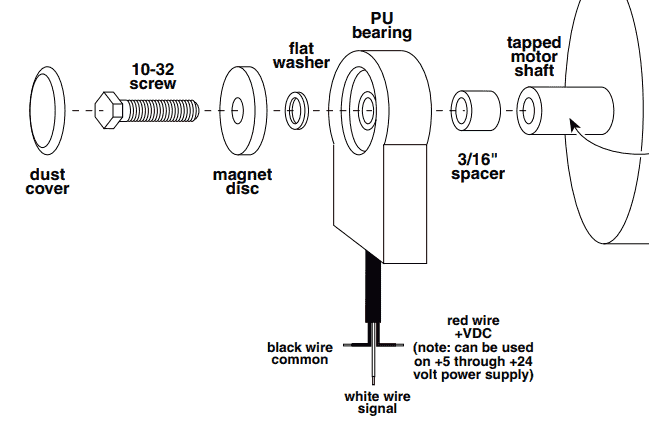
The Dart PU Series pick-up is an economical and reliable way to monitor motor speed. Its unique design provides ease of installation in otherwise difficult to reach areas.
The PU pick-up operates at a 5 to 24 volt level producing a sharp square wave output, which may be fed into Dart’s field programmable tachometer, closed-loop control, counter, or any other digital device.
There are two versions of the product: The PU-E is rated for indoor industrial applications. The NEW PU-R is rated NEMA 4 for outdoor applications where temperature, humidity, rain and dust are present. The PU-R is also recommended for applications where water washdown is expected.
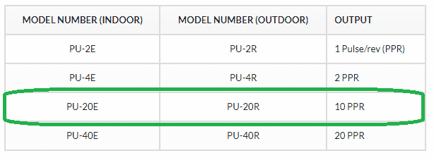
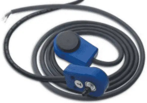
Completely self contained, the PU Series eliminates the alignment hassle found with other devices. Encapsulated sensor head is dust and dirt resistant. Includes 6 feet of highly flexible, UV resistant cable. An excellent ‘Motor Not Running’ feedback device to plc/SCADA systems. We will be wiring the dart PU-20E into our Click PLC. This will provide 10 pulses per revolution.
Purchase on Ebay
Wiring the PU-20E to the Click PLC
The Dart PU Series pick-up can be wired as a sinking encoder (open collector) or a sourcing encoder. This will allow you to match the existing wiring of your control circuit. We will wire our PU-20E as a sinking encoder input to the Click PLC.
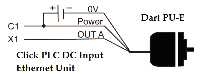
In our example C1 is wired to the +24VDC supply along with the red wire of the PU-20E. The black wire of the PU-20E is connected to the 0VDC and the white (switching) wire is wired to our first input X1.
Programming the High Speed Counter
You must have Click Software 2.30 or higher along with the updated firmware of the Ethernet unit with DC inputs to program the high speed counter(s).
Firmware Update – Video
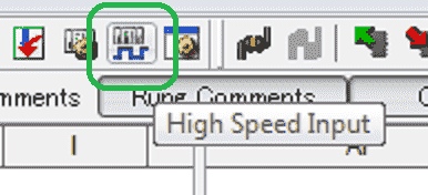
Select the High Speed Input Icon from the main menu to get to the High Speed Input Configuration window.
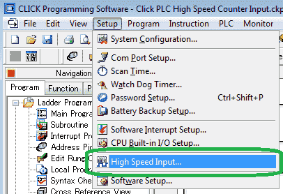
You can also select High Speed Input… from the main menu | Setup.
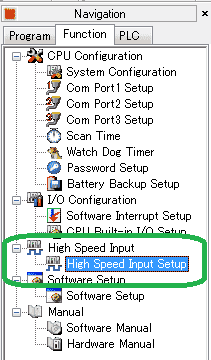
A third way to get to the High Speed Input Configuration window is to select High Speed Input Setup under the High Speed Input heading in the Function tab of the Navigation window.
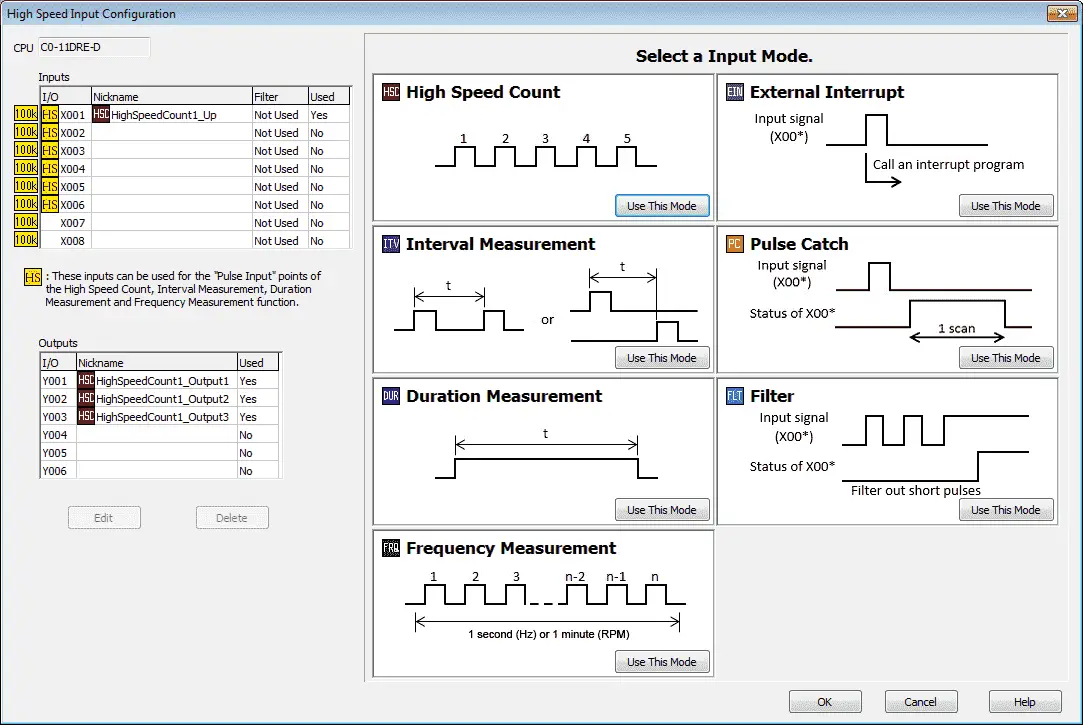
The High Speed Input Configuration window will now be displayed. This is where you will program all of the functions related to the high speed counter.
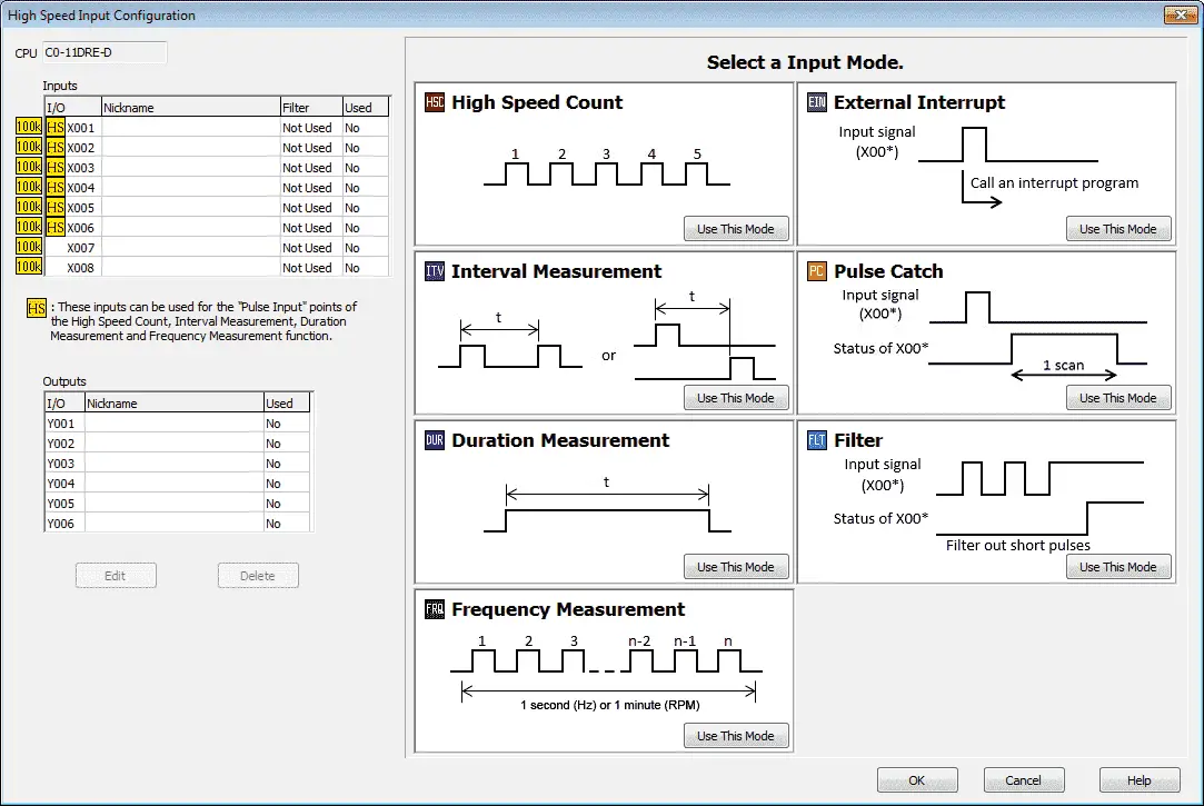
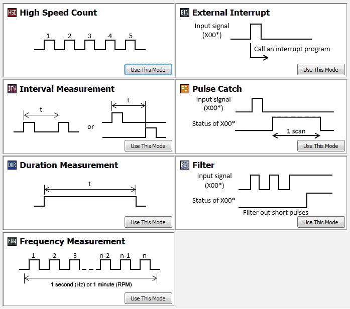
You will see the CPU inputs available for the high speed counter modes on the top left corner of the window. This is based on the selection of the Click CPU model number. Below them you will see the outputs available. All seven of the input modes for the high speed counter are indicated to the right along with a timing chart of the function.
Note: HS indication means that you can use all of the modes including the High Speed Count, Interval Measurement, Duration Measurement and Frequency Measurement functions on these inputs. Inputs not marked with HS can use the External Interrupt, Pulse Catch and Filter modes only.
High Speed Count Mode
The High Speed Count mode operates independently of the CPU program scan. Up to 6 Single-Input Counters or 3 Dual-Input Counters can be configured. Outputs can be directly controlled based upon the set points programmed.
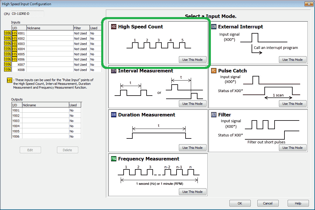
Select the ‘Use This Mode’ under the High Speed Count on the High Speed Input Configuration window.
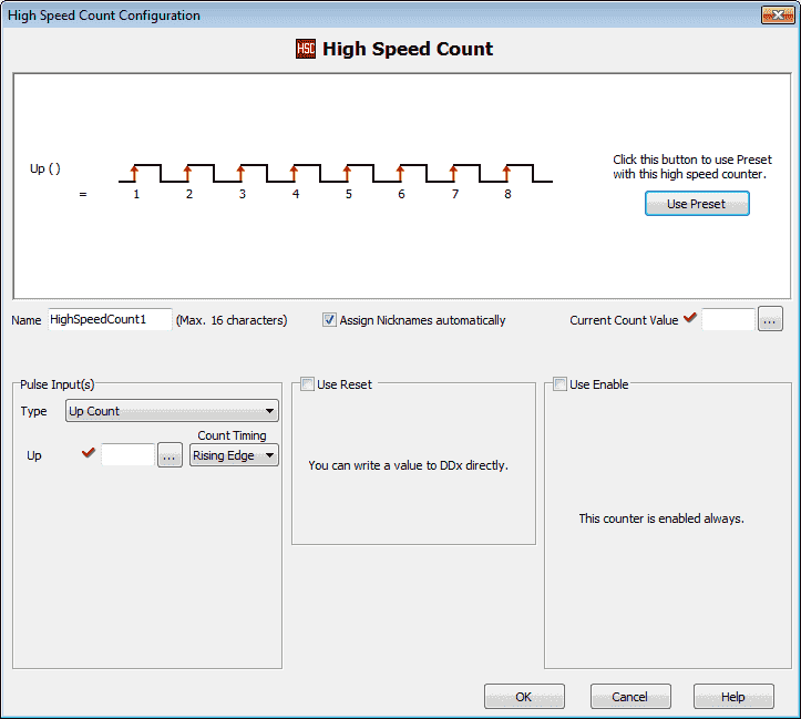
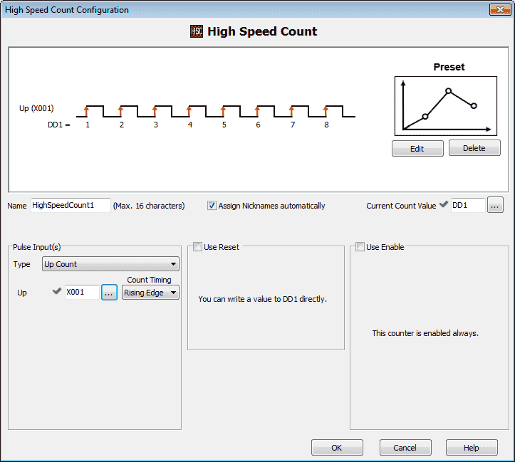
You will now see the High Speed Count mode menu. A timing chart is displayed indicting the way in which this mode will operate based on the current selections. We will be leaving most of these settings as default.
Name : This is the default name for the high speed count. HighSpeedCount1.
Assign Nicknames automatically – leave checked
Current Count Value – Set to DD1 – This is the current (PV) present value of the high speed counter. The red checkmark indicates on this screen that the option must be set.
Pulse Input(s)
Type – Select Up Count. This is where we would select all of the different modes for this mode of counter.
Up – Set to X1 Rising Edge. This setting is dependent on the selection of the type. It indicates what physical inputs will be used.
Use Reset – Select this if you want to indicate a bit to reset the count. We will leave this off.
Use Enable – Select this if you want a bit to enable the counting. We will leave this off.
Select ‘Use Preset’
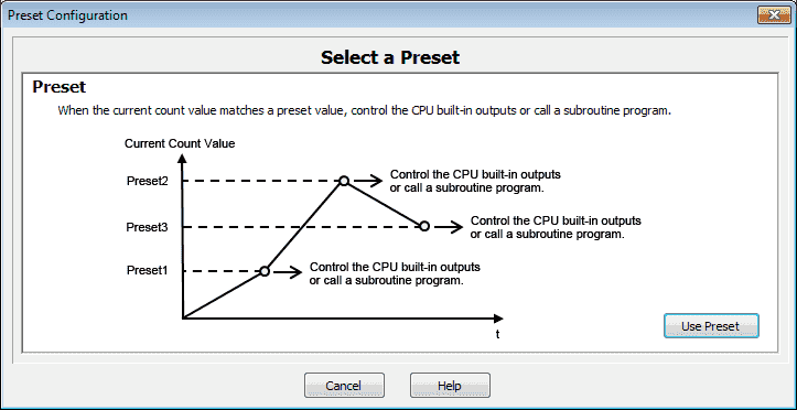
The preset configuration window will now be displayed. Presets enable us to control the CPU built in outputs or call a subroutine program based upon a value that matches the count value. Select ‘Use Preset’.
Our preset configuration window will not be displayed. A picture representing the timing chart will be shown based upon the parameters set.
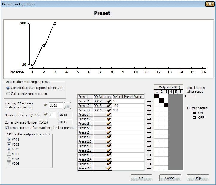
Action after matching a preset – select Control discrete outputs built in CPU.
Starting DD address to store parameters – Select DD10
Number of Presets – We will program in 3 preset values. This is the first parameter word DD10 set above.
Current Preset Number (1 – 16) – This is shown so you know where to look for the information. (DD11)
Reset counter after matching the last preset – Select this option so the count will reset automatically for us instead of writing some ladder logic to do this operation.
CPU built in outputs to control – We can select the first three outputs on the CPU to control.
Preset 1 – DD12 – Set for a value of 10
Preset 1 – DD13 – Set for a value of 100
Preset 1 – DD14 – Set for a value of 200
We can now click on the outputs to indicate when they will be turned on/off in relationship to the preset values set above. In our case Y1 will turn on when the count is reset to the count value of 10. Y2 will be on when the count value is between 10 and 100. Y3 is turned on when the count value is between 100 and 200.
Select OK to save and exit the preset configuration window. Watch the video below to see this mode in action.
Here is our completed High Speed Count mode window. Select OK to save and exit.
Here is our completed High Speed Input Configuration window. You can quickly see that we have used X1 for out count and the first three outputs for control.
Watch on YouTube : Click PLC High Speed Count Mode Video
Interval Measurement Mode
The Interval Measurement measures the time between two edges. The two edges can be of a single input, or edges from two different inputs.
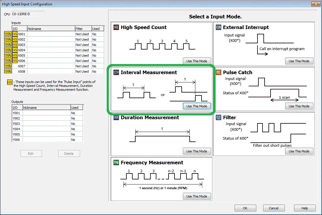
Select the ‘Use This Mode’ under the Interval Measurement on the High Speed Input Configuration window.
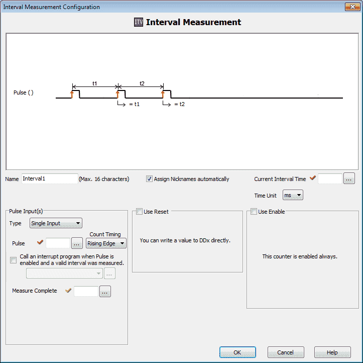
You will now see the interval measurement configuration mode menu. A timing chart is displayed indicting the way in which this mode will operate based on the current selections. We will be leaving most of these settings as default.
Name : This is the default name for the high speed count. Interval1.
Assign Nicknames automatically – leave checked
Current Interval Time – Set to DD1 – This is the current time interval measured. The red checkmark indicates on this screen that the option must be set.
Time Unit – This is the units that the interval will be measured. Set to us (microseconds).
Pulse Input(s)
Type – Select Single Input. This can be set for Single or Dual input measurement.
Pulse – Set to X1 Rising Edge. This setting is dependent on the selection of the type. It indicates what physical inputs will be used.
Use Reset – Select this if you want to indicate a bit to reset the measurement. We will leave this off.
Use Enable – Select this if you want a bit to enable the measurement. We will leave this off.
Call an Interrupt program when Pulse is enabled and a valid interval was measured – use this option to select the interrupt program to run. We will leave this off.
Measure Complete – This bit is Set after each measurement. Rung logic should be used to Reset the bit. We will not set a bit.
Watch the video below to see the interval measurement in action.
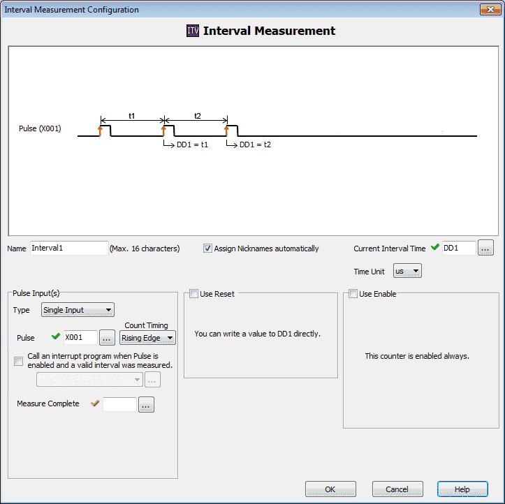
Here is the completed interval measurement configuration window. Select OK to save and return to the High Speed Input Configuration window.
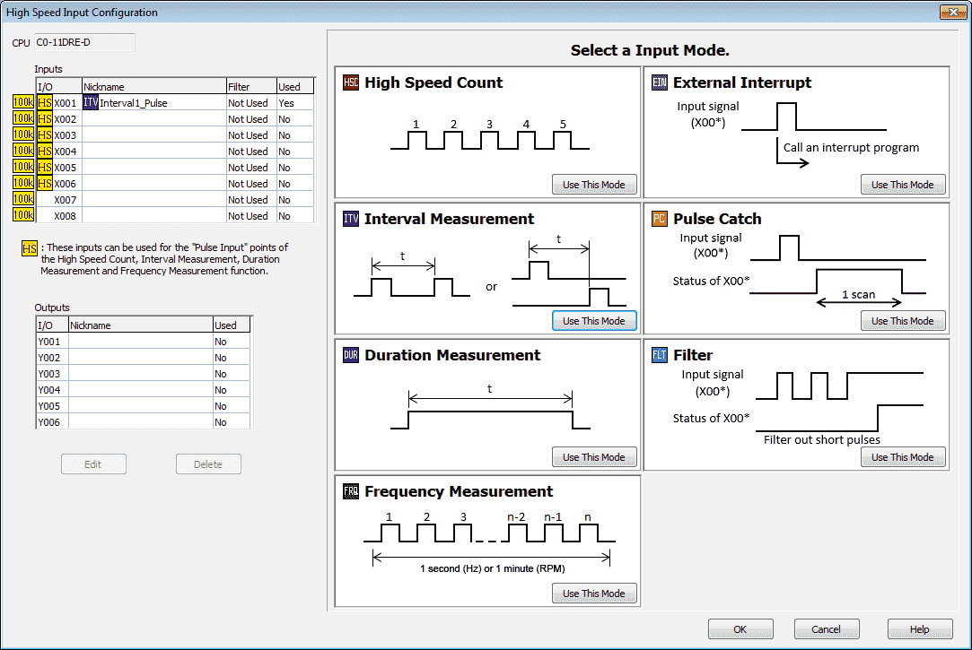
You can quickly see that we are using X1 as our input for the Interval Measurement.
Watch on YouTube : Click PLC Interval Measurement Mode Video
Duration Measurement Mode
The Duration Measurement measures either the On or Off length of a pulse
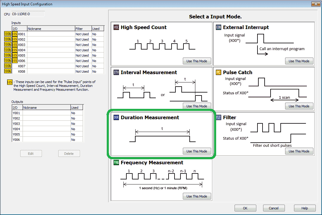
Select the ‘Use This Mode’ under the Duration Measurement on the High Speed Input Configuration window.
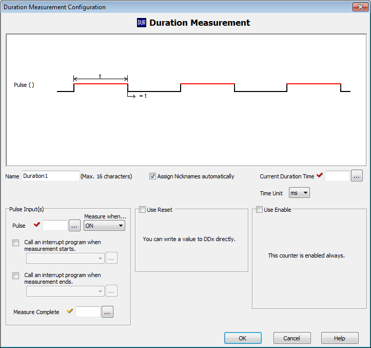
You will now see the duration measurement configuration mode menu. A timing chart is displayed indicting the way in which this mode will operate based on the current selections. We will be leaving most of these settings as default.
Name : This is the default name for the high speed count. Duration1.
Assign Nicknames automatically – leave checked
Current Duration Time – Set to DD1 – This is the current time duration measured. The red checkmark indicates on this screen that the option must be set.
Time Unit – This is the units that the interval will be measured. Set to us (microseconds).
Pulse Input(s)
Pulse – Set to X1. This indicates what physical input will be used.
Measured when… – This will determine if you are measuring the input pulse on or off. Leave this as the default ON.
Use Reset – Select this if you want to indicate a bit to reset the time measured. We will leave this off.
Use Enable – Select this if you want a bit to enable the time measured. We will leave this off.
Call an Interrupt program when measurement starts – use this option to select the interrupt program to run. We will leave this off.
Call an Interrupt program when measurement ends – use this option to select the interrupt program to run. We will leave this off.
Measure Complete – This bit is Set after each measurement. Rung logic should be used to Reset the bit. We will not set a bit.
Watch the video below to see the duration measurement in action.
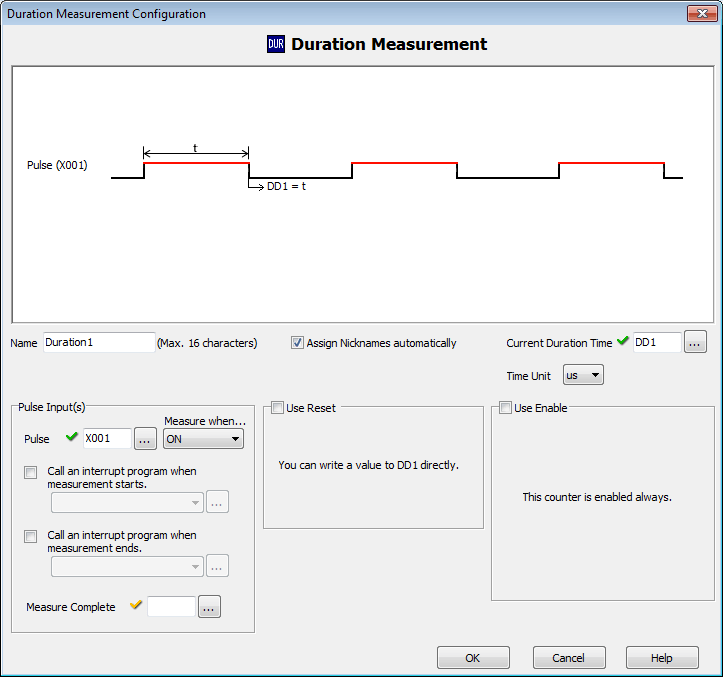
Here is the completed duration measurement configuration window. Select OK to save and return to the High Speed Input Configuration window.
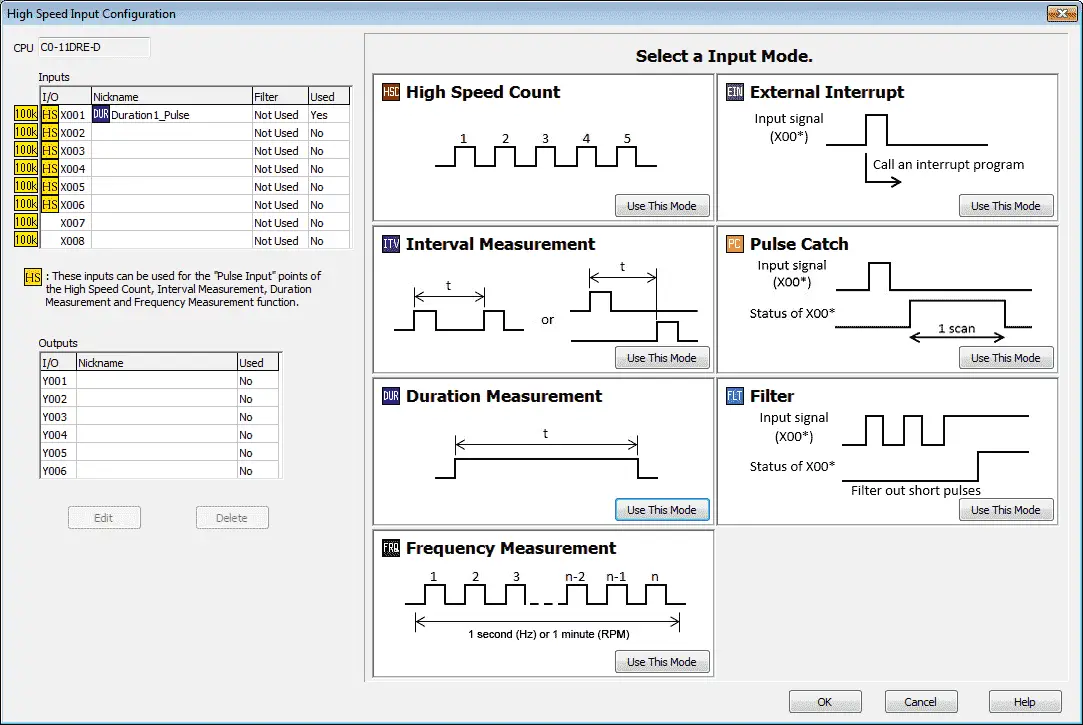
You can quickly see that we are using X1 as our input for the Duration Measurement.
Watch on YouTube : Click PLC Duration Measurement Mode Video
Frequency Measurement Mode
The Frequency Measurement is selectable for either Hz or RPM. Hertz is the number of pulses counted during 1 Second. The actual value provided is a moving average (16 times) by measuring the number of pulses for 100ms. RPM is the number of revolutions during 1 Minute.
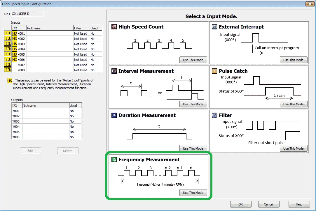
Select the ‘Use This Mode’ under the Frequency Measurement on the High Speed Input Configuration window.
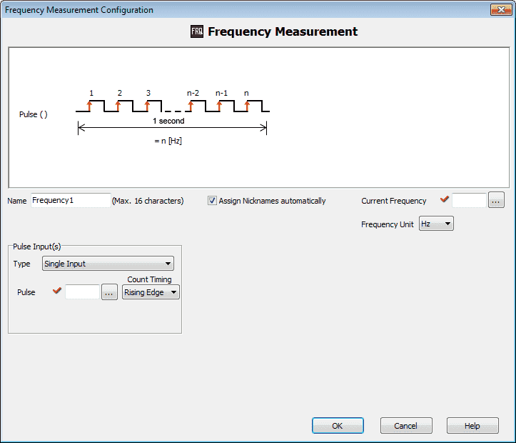
You will now see the frequency measurement configuration mode menu. A timing chart is displayed indicting the way in which this mode will operate based on the current selections. We will be leaving most of these settings as default.
Name : This is the default name for the high speed count. Frequency1.
Assign Nicknames automatically – leave checked
Current Frequency – Set to DD1 – This is the current frequency measured. The red checkmark indicates on this screen that the option must be set.
Frequency Unit – This will indicate the number of pulses per second. (Hz) You can also select RPM. Revolutions per minute will calculate the number of pulses received every minute.
Pulse Input(s)
Type – This determines if we have a single input or quadrature. We will leave this as a single input.
Pulse – Set to X1. This indicates what physical input will be used.
Count Timing – Rising Edge or Trailing Edge can be configured for the timing. We will leave this as the default rising edge.
Watch the video below to see the frequency measurement in action.
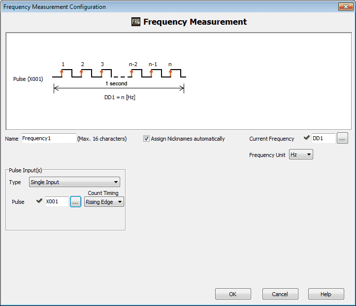
Here is the completed duration measurement configuration window. Select OK to save and return to the High Speed Input Configuration window.
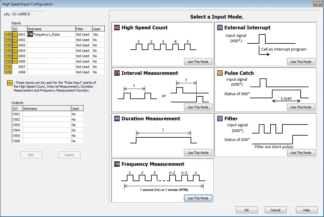
You can quickly see that we are using X1 as our input for the Frequency Measurement.
We will add the following line to turn on an output when the frequency measurement is zero. This indicates that the pulses (motor) have stopped.
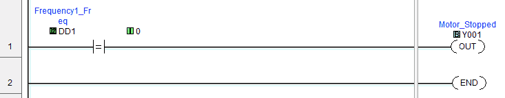
The current frequency (DD1) is compared to 0. If equal then output Y1 is turned on.
Watch on YouTube : Click PLC Frequency Measurement Mode Video
Download the Click PLC programs here.
Next time we will be looking at the External Interrupt, Pulse Catch and Filter Modes of the Click high speed counter. Combining Frequency Measurement and High Speed Count Mode will also be demonstrated.
Click PLC Support Links
The Click PLC can be programmed using free Click programming software from Automation Direct. Here is a link for the software.
https://support.automationdirect.com/products/clickplcs.html
The following links will help you to install the software and establish communication.
https://accautomation.ca/click-plc-installing-the-software/
https://accautomation.ca/click-plc-establish-communication/
The entire Click PLC series can be found at the following URL:
https://accautomation.ca/series/click-plc/
If you have any questions or need further information please contact me.
Thank you,
Garry
If you’re like most of my readers, you’re committed to learning about technology. Numbering systems used in PLC’s are not difficult to learn and understand. We will walk through the numbering systems used in PLCs. This includes Bits, Decimal, Hexadecimal, ASCII and Floating Point.
To get this free article, subscribe to my free email newsletter.
Use the information to inform other people how numbering systems work. Sign up now.

The ‘Robust Data Logging for Free’ eBook is also available as a free download. The link is included when you subscribe to ACC Automation.