We will now look at the programming and wiring of a rotary encoder to the Click PLC input. Rotary encoders are modern digital devices that have taken over from the potentiometer in stereos and many other applications. This is because of their fine digital control, and they can fully rotate without end stops. We can connect the rotary encoder to the PLC using just two digital inputs. This human-machine interface (HMI) has the advantage over touch screens and other control methods in the PLC. The operator can control the rate and setpoint with the dial (rotary encoder) without looking at the control. This will allow the operator to concentrate on other tasks.

We will be connecting a rotary encoder with a dial into the Click PLC. The signals being sent from the rotary encoder will be explained. Different methods of programming this input in our PLC will be discussed. Let’s get started.
Previously in this series, we have discussed:
System Hardware – Video
Installing the Software – Video
Establish Communication – Video
Numbering System and Addressing – Video
Timers and Counters
– Counter Video
– Timer Video
Compare and Math Instructions – Video
Program Control Instructions – Video
Shift Register – Video
Drum Instruction – Video
Send and Receive Instructions – Video
AdvancedHMI Communication – Video
Firmware Update – Video
Create an Analog Voltage Input Tester for a PLC – Video
Wiring Testing Analog PLC Input Click – Video
Modbus RTU Click PLC Master to BRX PLC Slave Communication – Video
The programming software and manuals can be downloaded from the Automation Direct website.
Rotary Encoder – Hardware
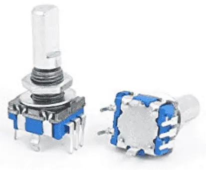
We will be using a rotary encoder that has 20 momentary resting points within the 360-degree rotation. These dent locations give the operator a feel for the movement of the PLC input. Here are the specifications of the rotary encoder we will be using:
• Material: plastic, metal, encoder switch
• Net weight: 12G
• Main color: silver tone, blue
• Size shaft: 6 x 13mm / 0.24 ‘x 0.5’ (D * L)
• Thread DIA: 7mm / 0,28 ‘
• Total size: 15 x 12 x 30 mm / 0.6 ‘x 0.47’ x 1.2 ‘(L * W * H)
• Wave direction: 360 degrees
• Action Type: Momentary
• Resting points: 20
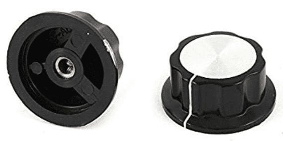
Attached to the rotary encoder will be our dial. The dial is a black 36mm top rotary with a 6mm diameter shaft.
Amazon.com
Amazon.ca
Wiring the Rotary Encoder to Click PLC Input
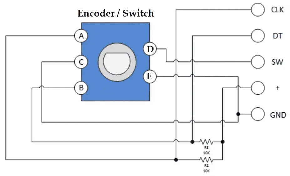
The rotary encoder has open collector outputs. Our PLC will act as the load (resistance) in the above diagram.
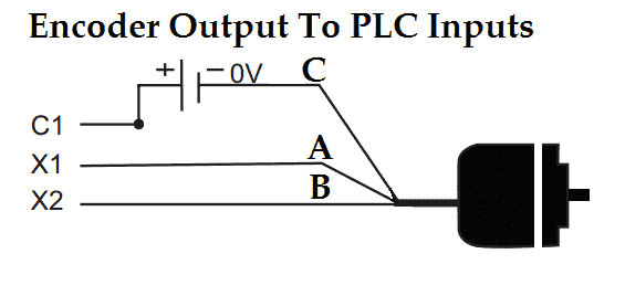
You will see that our standard PLC input will be at +24VDC. We will be wiring the encoder inputs as follows:
X2 – A phase of the rotary encoder
X3 – B phase of the rotary encoder
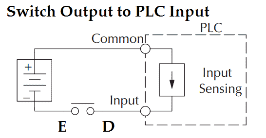
Our rotary encoder also comes with a switch. This is momentary upon pressing down on the encoder. We will be wiring this encoder switch into X1 of our Click PLC.
Rotary Encoder Operation – Input Signals
The rotary encoder has two square wave outputs (A and B) 90 degrees out of phase with each other. The number of pulses or steps generated per complete turn varies. This Rotary Encoder has 20 steps, but others may have more or less. The diagram below shows how phases A and B relate to each other when the encoder is turned clockwise or counterclockwise.
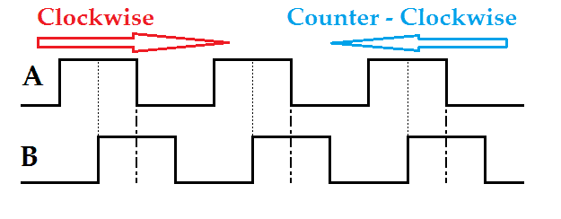
As we rotate clockwise, phase A will turn on, and we can trigger the input when phase B transitions from off to on. When we rotate counterclockwise, phase B will turn on, and we can begin the information when phase A transitions from off to on. It is essential to pick up the direction so we can increase or decrease the value in the PLC.
Programming the Click PLC for Encoder Input
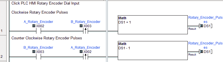
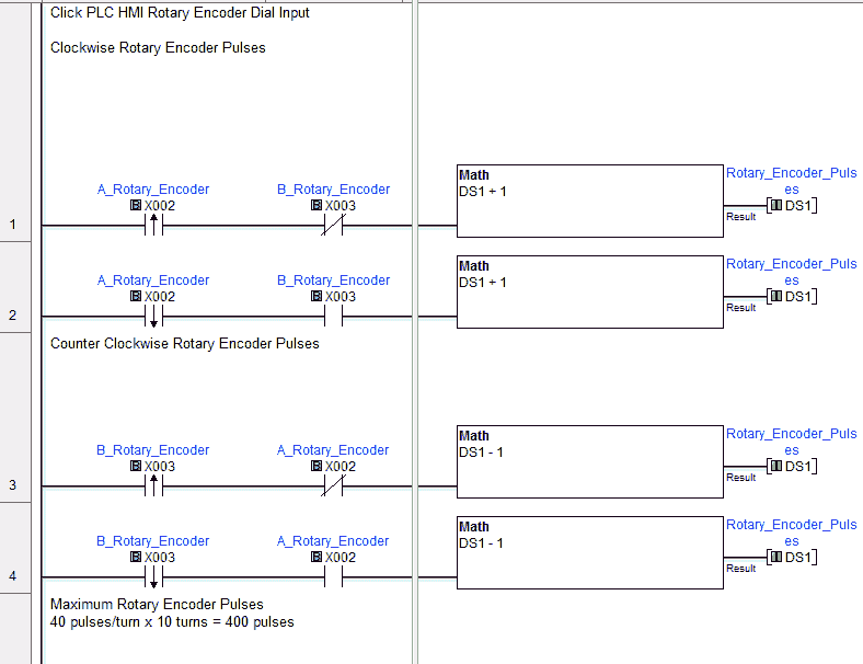
When the dial is turned clockwise, we look for the A-phase to be on and the leading edge of the B phase. Memory location DS1 is incremented by 1.
When the dial is turned counterclockwise, we look for the B phase to be on and the leading edge of the A phase. Memory location DS1 is decremented by 1.
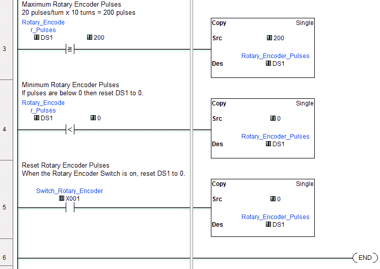
Our program will make this a ten-turn maximum on the dial. This means that we will have a maximum limit of 200 pulses. (20 pulses/turn x 10 turns = 200 pulses)
We compare DS1 with the maximum count of 200. If it is more significant than 200, we will move 200 back into DS1.
The smallest value in DS1 will be 0. We make a comparison on DS1 for deals less than 0, and if this is true, we move 0 into DS1 to ensure that it is not below the value of 0.
Our rotary encoder switch will be used to reset the current value in DS1 to 0. If X1 turns on, the value of 0 is moved to DS1.
We have used 20 counts per revolution in our program because this is where the dents are on the rotary encoder. Forty counts per revolution are possible because we can pick up on each phase’s leading and trailing edge.
As we pick up on the leading and trailing edge of the A-phase, the state of the B phase will determine when to increment the count.
The leading and trailing edge of the B phase and the state of the A-phase will determine when to decrement the count.
Watch the video below to see the Click PLC HMI Rotary Encoder Input.
Download the Click PLC programs here. (20 pulses / turn and 40 pulses / turn)
Click PLC Support Links
The Click PLC can be programmed using free Click programming software from Automation Direct. Here is a link to the software.
https://support.automationdirect.com/products/clickplcs.html
The following links will help you to install the software and establish communication.
https://accautomation.ca/click-plc-installing-the-software/
https://accautomation.ca/click-plc-establish-communication/
The entire Click PLC series can be found at the following URL:
https://accautomation.ca/series/click-plc/
Watch on YouTube: Click PLC HMI Rotary Encoder Dial Input
If you have any questions or need further information, please contact me.
Thank you,
Garry
If you’re like most of my readers, you’re committed to learning about technology. Numbering systems used in PLCs are not challenging to learn and understand. We will walk through the numbering systems used in PLCs. This includes Bits, Decimal, Hexadecimal, ASCII, and Floating Point.
To get this free article, subscribe to my free email newsletter.
Use the information to inform other people how numbering systems work. Sign up now.

The ‘Robust Data Logging for Free’ eBook is also available for free download. The link is included when you subscribe to ACC Automation.