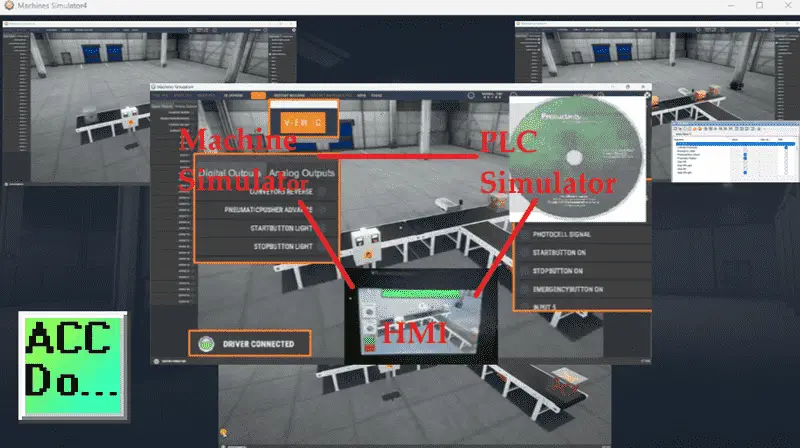
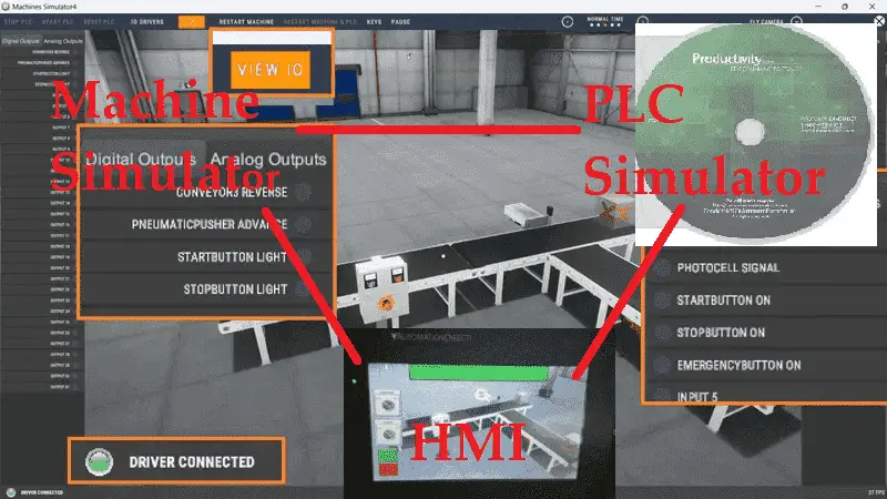
Previously, we learned that only 31% of businesses have fully automated at least one function (McKinsey). There is a massive demand for automation and creating training environments. Using the machine simulator, we utilized the Modbus TCP (Ethernet) Server in the “Easy Transfer Line.” This is just one of many pre-built scenes, or you can design your own for your industry. This set the stage for the Productivity PLC Simulator to communicate and control the line. We programmed the PLC, tested, and monitored our system.

We will now add a human-machine interface (HMI) to our system. Modifying the PLC logic to accommodate the controls from the touch screen, we will add a C-More CM5 unit. This HMI will communicate with the productivity PLC simulator and the easy transfer line machine. This will create our ultimate automation training environment. Let’s get started.
Learn PLC programming the easy way. See below for a 10% discount on this cost-effective learning automation tool. Invest in yourself today.
Previously, we have done the following:
Easy PLC Installing the Software – Video
EasyPLC Software Suite – Quick Start – Video
Click PLC – Easy Transfer Line Programming – Video
Productivity PLC Simulator – Chain Conveyor MS – Video
Do-More PLC – EasyPLC Box Selection Program – Video
Click PLC EasyPLC Gantry Simulator – Video
Click PLC Simple Conveyor EasyPLC – Video
EasyPLC Paint Line Bit Shift – BRX Do-More PLC – Video
Click PLC – EasyPLC PLC Mixer Programming – Video
Click PLC EasyPLC Warehouse Stacker Example – Video
– Operation Video
EasyPLC Machine Simulator Productivity PLC Robotic Cell – Video
EasyPLC Simulator Robotic Cell Click PLC – Video
Palletizing Conveyor Programming Do-More PLC – Video
Palletizing Conveyor Programming – Click PLC – Video
Product Quality Verification! Do-More PLC Sequencer – Video
Revolutionize Learning PLCs with Pallet 3D Sim! – Video
Robot Packing PLC Program Development – Video
Box Dumper Easily Learn PLC Programming – Video
Innovative Solution for Mixing Ink and Bottling – Video
Benchwork 1 Do-More Practice PLC Programming – Video
LS Electric XGB PLC Easy Transfer Program – Video
Do-More PLC Automatic Robot Packing Machine – Video
Latest Machine Simulator Modbus Server Driver – Video
Machine Simulator Modbus Server to C-More HMI – Video
Creating the Ultimate Automation Training Setup
– Part 1 – Video
PLC / HMI Program Development
Our machine simulator runs with the easy transfer line scene using a Modbus TCP server. The PLC simulator was programmed to control the easy transfer line in part 1 of the tutorial. We need to determine now what and how the HMI will communicate. The following diagram will explain the communication between the three devices.

The C-More CM5 will communicate to our easy transfer line and the Productivity Suite PLC Simulator. It will read the inputs from the easy transfer line and set outputs to control the logic to the PLC simulator. The following table will show the communication from each device in our network.
| Machine Simulator (MS) Description |
(MS) Modbus Server Address | Productivity PLC Address | Read /Write |
C-More HMI | Read /Write |
| Conveyor | 1 | Conveyor | W | ||
| Pneumatic Pusher | 2 | Pneumatic Pusher | W | ||
| Start PB Light | 3 | Start PB Light | W | ||
| Stop PB Light | 4 | Stop PB Light | W | ||
| Pneumatic Cylinder Extended | 100001 | Cylinder Extended | R | Cyl_Ext | R |
| Photocell | 100002 | Photocell Box Detect | R | Photocell | R |
| Start PB | 100003 | Start PB | R | Start_PB | R |
| Stop PB | 100004 | Stop PB | R | Stop_PB | R |
| Emergency Stop | 100005 | Emergency Stop | R | Emergency_Stop | R |
| HMI_Conveyor | W | HMI_Conveyor | W | ||
| HMI_Pne_Pusher | W | HMI_Pne_Pusher | W | ||
| HMI_Start_Light | W | HMI_Start_Light | W | ||
| HMI_Stop_Light | W | HMI_Stop_Light | W | ||
| HMI_Test | W | HMI_Test | W |
Using the code in the post “Machine Simulator Modbus Server to C-More HMI,” we will modify this CM5 program. This will include adding the communication protocol to the productivity PLC simulator and modifying the existing write commands.

Our HMI screen will use the condition of the “HMI Test” switch to enable the write items on the screen to test.
Modifying the Productivity Suite PLC Program
Our automation learning program last time included the Mobus TCP communications and ladder logic control for the Easy Transfer Line of the Machine simulator. We will now add the controls from the HMI to control the transfer line. Our C-More CM5 HMI will have a test button. The corresponding outputs can be energized when this test button is turned on.
![]()
The automation logic will have the test button and the corresponding output test button parallel to the original circuit. In the case of the set and reset instructions, this will have the Test and the normally open and normally closed of the output test button.
Remember to save the program logic often so you will not lose any of your logic if something happens.
![]()
To ensure that the existing logic continues to work, we will also set the HMI_Test, not input, for each of the output rungs that are being controlled. The automation logic will work such that if the Test is not on, then the logic will control the outputs. If the Test is on, the individual output test switches on the HMI will control the outputs.
Save the learning program and transfer it to the PLC simulator.
![]()
To export our ladder logic tags to the C-More CM5 HMI, select tags… from the main menu | File | Export. The Export Tag Database window will be displayed. You can change where the tags will be stored using the “Browse” button. We will leave this as the default and select Export. The Export finished notification will be displayed. Select OK.
Modify the C-More CM5 HMI Program
Using the code in the post “Machine Simulator Modbus Server to C-More HMI,” we will now modify this CM5 program. This sample automation HMI code communicated directly to the Machine Simulators Easy Line Transfer. It controlled the outputs directly and monitored the inputs. You can watch the video on how this is accomplished here.
The first thing we will do when modifying the HMI program is add communication to our PLC Simulator.
![]()
Select the protocol manager icon on the home screen tab.
![]()
The protocol manager window will be displayed. This will show our current communication using Modbus TCP to the Machine Simulator. Select the Add button.
The “Add New Device” window will be displayed. We will leave the device name as the default of DEV002. Select Automation Direct as the PLC vendor and Productivity Ethernet as the Protocol Type. Select OK.
![]()
The protocol manager window will be displayed. Enter the computer’s IP address running the Productivity Programming Suite PLC Simulator.
Note: You can have only one slave device per IP address. Since we have the Easy Transfer Line as the slave on one computer, you must run the PLC simulator on another. The PLC simulator will act as a Modbus Slave (Server) and Modbus Master (Client).
We will leave all of the other settings as their default. Select OK.
![]()
Select File | Import | Tag Name Database… This will call up the Open window to select the PLC programming tags that we saved previously. Select the exporttags_basic.csv (Basic) file and choose Open.
![]()
The import tag name database window will be displayed. Under device, select DEV002. Select overwrite existing tags and choose Import. The import complete message will be displayed after the tags are imported into the C-More programming software. Select OK.
![]()
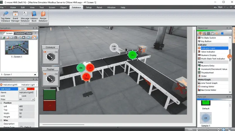
We can now rearrange the existing output controls on our troubleshooting screen. We will duplicate our conveyor switch. The tag name will be set to HMI_Test, and the object type will be left as a toggle. The name will be changed to Test.
We can now change the other output switches and indicators to reflect the test option from the PLC program. All of these object types will be set for “Momentary On.” This means the input will be turned on as long as the HMI button is selected. We will set the object visibility option under the options tab of the test switches and indicators. When the HMI_Test is on, the rest of the test outputs will be visible. Save the C-More CM5 HMI program.
![]()
This finishes our current HMI for our automation learning environment. Watch the video below to see how this HMI screen is being modified.
Download and Test the HMI program in our Ultimate Automation Environment.
To download the HMI program to the CM5 unit, select the Project Transfer icon on the home tab.
![]()
The project transfer window will be displayed. If our controller is not automatically found, we can select the Browse button.
![]()
Under the Ethernet Connection Setup window, you can choose the panel and OK.
![]()
We can now select the Transfer button on the project transfer window. Our project will now be transferred. A message will indicate when the transfer has been completed. Select OK.
We can now test our HMI in our automation environment.
![]()
Select the View IO on our machine simulator. This will show the status of the inputs and outputs. We can select the test button on the HMI and test our outputs. Ensure you thoroughly test all of the functions on our ultimate automation machine. Any errors can then be easily changed and tested.
![]()
So, what makes an ideal training environment? There are several key components to consider. Technology plays a vital role. Access to relevant software, hardware, and tools is essential for developing your skills. Next, the content should be carefully designed to cover both theoretical and practical aspects of automation. In addition to these, hands-on experience is crucial. You must work on real-world projects and simulate real-world scenarios to develop the necessary skills and confidence. Finally, mentorship and guidance from experienced professionals can make a significant difference in your outcomes.
The C-More CM5 is more than just an HMI. We can log data, send emails, communicate with multiple devices, display it on a TV screen, etc. To learn more about this industrial touch screen, click here.
Click here to learn more about the Machine Simulator, formally known as EasyPLC.
Click here to learn more about Node-RED and how you can add additional capabilities to your ultimate automation learning environment.
Download the PLC sample PLC and HMI program here.
Watch the video below to see how the Productivity PLC Simulator controls the Easy Transfer Line. This is the first step in creating the ultimate automation training setup.
When using the Machine Simulator Software Suite, debugging is quickly done without damaging equipment. You may modify your logic several times before you get everything right! This is all part of automation learning. To learn more about developing logic, check out our tutorials on the five steps to PLC program development.
Watch on YouTube: Creating the Ultimate Automation Training Setup Part 2
Machine Simulator (EasyPLC) Software Suite is a complete PLC, HMI, and Machine Simulator Software package. This PLC automation learning package includes the following:
Easy PLC – PLC Simulation allows programming in Ladder, Grafcet, Logic Blocks, or Script.
HMI System – Easily create a visual human-machine interface (HMI)
Machine Simulator – A virtual 3D world with real-time graphics and physical properties. PLC programs can be tested using EasyPLC or through other interfaces. (Modbus RTU, TCP, etc.)
Machine Simulator Lite – Designed to run on Android Devices.
Machine Simulator VR – Virtual Reality comes to life so you can test, train, or practice your PLC programming.
Purchase your copy of this automation learning package for less than USD 95 for a single computer install or less than USD 110 to allow different computers.
Receive 10% off the price by typing in ACC in the comment section when you order. http://www.nirtec.com/index.php/purchase-price/
Learn PLC programming the easy way. Invest in yourself today.
If you have any questions or need further information, please get in touch with me.
Thank you,
Garry
If you’re like most of my readers, you’re committed to learning about automation technology. Numbering systems used in PLCs are not challenging to know and understand. We will walk through the numbering systems used in PLCs. This includes Bits, Decimals, Hexadecimal, ASCII, and Floating Points.
To get this free article, subscribe to my free email newsletter.
Use the information to inform other people how numbering systems work. Sign up now.
The ‘Robust Data Logging for Free’ eBook is also available for free download. The link is included when you subscribe to ACC Automation.


