The Productivity Suite Software comprises more than 82 instructions divided into 14 categories. These instructions include Out, Set, Reset, OR Out, Flasher, Debounce, Timed, Toggle, Program End, and No Operation. Coils (Outputs) are one of these categories of ladder logic instructions to program your productivity PLC controller. Ladder logic outputs or coils are in every PLC program.
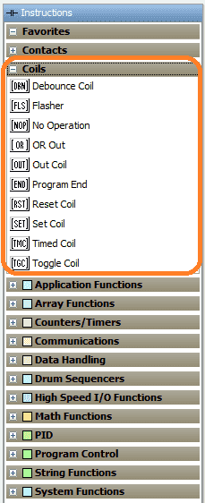 We will be looking at these instructions in the Productivity 2000 series PLC. We will also look at organizing your favorite instructions. This will make them easier to find when programming the productivity PLC. Let’s get started.
Previously in this Productivity 2000 series PLC, we have discussed:
P2000 Hardware Features – Video
Productivity Suite Software Install – Video
Communication (System Configuration) – Video
First Program – Video
Debug Mode – Video
PLC Program Documentation – Video
PLC CPU Display – Video
PLC Online Programming – Video
PLC Tag Database – Video
Ladder Logic Contacts – Video
Productivity PLC Instruction List
The Instruction List provides access to the programming Instructions for creating ladder logic.
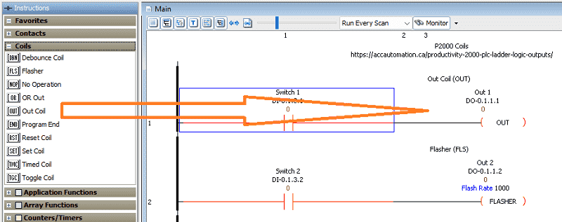 The Instruction List is displayed on the Main Screen and can be placed where desired. If the Instruction List is not shown, it can be accessed from the Tools Menu. Insert an Instruction into the Ladder Editor by clicking and dragging the instruction from the Instruction List to the desired rung position. You can also select the location in the Ladder Editor first and double-click the instruction in the Instruction List. The third way to choose instruction is to determine the area on the ladder editor and type in the Mnemonic (Keyboard Shortcut).
See the video below to change the location and display of the instruction list.
Favorites – Add / Remove
Favorites allow you to add any instruction to your list by right-clicking on the instruction and selecting Add to favorites. This allows easy access to your most commonly used instructions making programming more accessible.
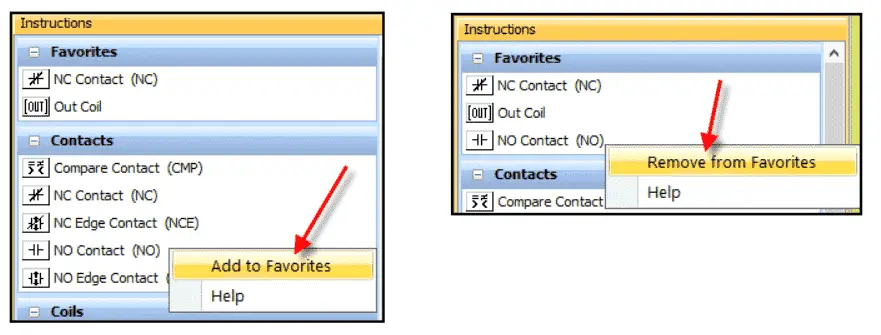 To Remove an instruction from the Favorites list, you can right-click the instruction and select Remove from Favorites.
Ladder Logic Outputs – Out Coil (OUT)
Out Coil (OUT) – This will provide an output that responds to the state of the rung. The one-shot selection will turn on the output for just one scan during a transition from off to on.
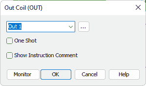
 In this ladder logic rung, when switch 1 is on the output is turned on. The output is turned on when an update is completed at the end of the PLC Scan.
Understanding the PLC Program Scan
How to make a one-shot in the PLC
Ladder Logic Outputs – Flasher (FLS)
Flasher (FLS) – This will cycle an output bit on and off at a programmed rate.
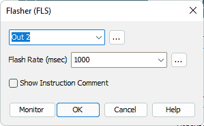
 We set the flasher cycle time. In our case, we are using 1000 milliseconds. This means that the output Out2 will be on for 0.5 seconds and off for 0.5 seconds when the rung condition is true.
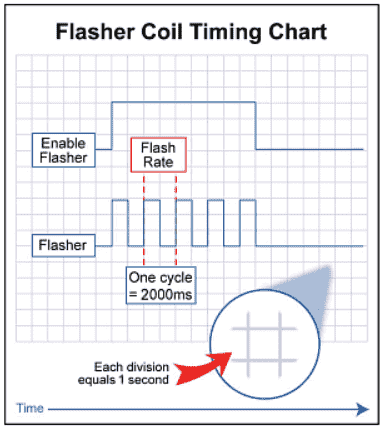 Here is the timing chart for the flasher instruction.
Ladder Logic Outputs – Debounce Coil (DBN)
Debounce Coil (DBN) – Eliminate output coil chatter due to run-enabling contact bounce. Chatter will occur if our logic allows things to turn off and on quickly. If we compare input and that input changes quickly above and below the compared number, this would create chatter.
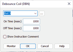
 In our example, the rung condition must be on or off for 1000 milliseconds (1 second) before the output will activate or deactivate. We are using the last logic scan to determine if the scan is less than 200 microseconds.
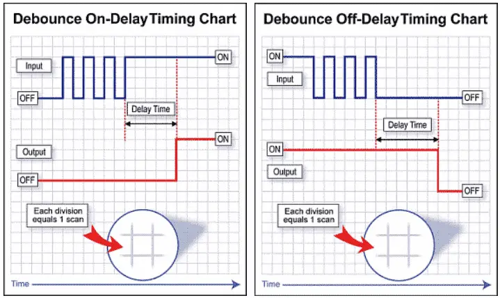 Here is the timing chart for the debounce coil instruction.
Ladder Logic Outputs – Or Out (OR)
Or Out (OR) – This instruction allows an out coil with the same tag to be used in multiple rungs.
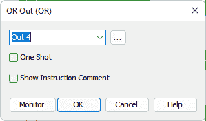
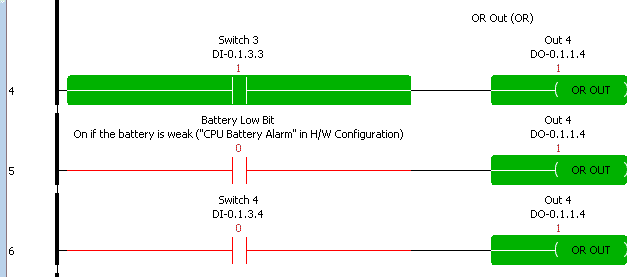 Note: The ability to have the same output in multiple rungs may make the troubleshooting of your logic difficult. In my experience, this should be avoided.
Ladder Logic Outputs – Set Coil (SET) / Reset Coil (RST)
Set Coil (SET) – Set the output in a latched condition when the rung is enabled.
Reset Coil (RST) – Reset the output (unlatch) of a corresponding set coil.
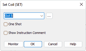
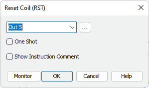
 The set and reset instructions are used together to turn on/off output. This is similar to the simple start-stop circuit that we discussed previously.
P2000 Series PLC First Program
How to Make a Start/Stop/Jog Circuit in a PLC
Ladder Logic Outputs – Timed Coil (TMC)
Timed Coil (TMC) – Hold the state of the output ON for a predetermined time.
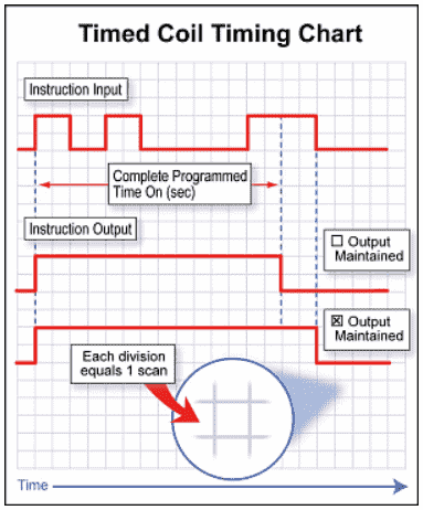 The output will complete the timed value duration before turning off. Output maintained will enable the output to remain on after the time as long as the input condition is on.
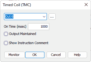

Ladder Logic Outputs – Toggle Coil (TGC)
Toggle Coil (TGC) – Change the state of the output each time the rung is enabled. (Flip Flop)
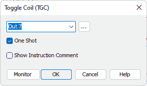
 In our example, when switch 8 is turned on the output will change state. If it is on then it will be turned off. If it is off then it will turn on. Here is a previous post explaining the logic behind the circuit.
Creating a Flip Flop Circuit in the PLC
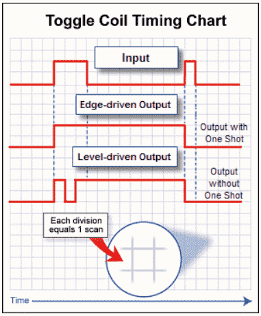 Here is the timing chart of the toggle coil instruction.
Ladder Logic Outputs – No Operation Coil (NOP)
No Operation Coil (NOP) – Indicates that the rung will have no operation. It is sometimes used as a placeholder in the ladder logic.

Ladder Logic Outputs – Program End Coil (END)
Program End Coil (END) – Marks the end of a task.

Watch the video below for the ladder logic output (coil) instructions in our Productivity 2000 Series PLC.
Download the Productivity 2000 PLC ladder logic program here.
Productivity 2000 Series PLC from Automation Direct
Overview Link (Additional Information on the Unit)
Configuration (Configure and purchase a system – BOM)
User Manual and Inserts (Installation and Setup Guides)
Productivity Suite Overview (Features of the fully functional free software package for the Productivity Family of PLC (PAC) controllers)
Productivity Suite Programming Software (Free Download Link)
This software contains all the instructions and helps files for the Productivity Series.
Watch on YouTube: Productivity 2000 PLC Ladder Logic Outputs
If you have any questions or need further information, please contact me.
Thank you,
Garry
If you’re like most of my readers, you’re committed to learning about technology. Numbering systems used in PLCs are not challenging to learn and understand. We will walk through the numbering systems used in PLCs. This includes Bits, Decimal, Hexadecimal, ASCII, and Floating Point.
To get this free article, subscribe to my free email newsletter.
Use the information to inform other people how numbering systems work. Sign up now.
The ‘Robust Data Logging for Free’ eBook is also available for free download. The link is included when you subscribe to ACC Automation.

