A rock crusher (jaw crushers) is also known as “rock breakers” and is used to break up larger, more complex materials into more manageable pieces. The EasyPLC simulator rock crusher plant will show you how you can control this process through a programmable logic controller. We will be using Do-More technology to control this plant automation.
 Using the five steps for PLC program development, we will discuss and show you how to program this rock crusher plant. An Automation Direct BRX Do-More PLC will be used for this application, but the general methods can be used for just about any PLC on the market. Let’s get started.
Learn PLC programming the easy way. See below how to receive a 10% discount on this already cost-effective learning tool. Invest in yourself today.
Previously we have done the following:
Easy PLC Installing the Software – Video
EasyPLC Software Suite – Quick Start – Video
Click PLC – Easy Transfer Line Programming – Video
Productivity PLC Simulator – Chain Conveyor MS – Video
Do-More PLC – EasyPLC Box Selection Program – Video
Click PLC EasyPLC Gantry Simulator – Video
Click PLC Simple Conveyor EasyPLC – Video
EasyPLC Paint Line Bit Shift – BRX Do-More PLC – Video
Click PLC – EasyPLC PLC Mixer Programming – Video
Click PLC EasyPLC Warehouse Stacker Example – Video
– Operation Video
EasyPLC Machine Simulator Productivity PLC Robotic Cell – Video
EasyPLC Simulator Robotic Cell Click PLC – Video
EasyPLC Simulator Robotic Cell BRX Do-More PLC – Video
– EasyPLC Factory Editor Robotic Cell Additions Video
4 Way Traffic Light PLC Program EasyPLC – Video
Define the task: (Step 1 – Rock Crusher Plant EasyPLC)
The first step of PLC program development is determining what must be done.
Feed the crusher 1 with large stone blocks. Use the separator to filter the small rocks that must be sent to the reject container via the conveyor belt. Feed the second crusher with the crushed stones from crusher 1. Load the transport boxes with the crushed rocks. Each box weights 5KG so only 5 KG of crushed rocks will be placed into each box. It uses the weighing system to release the box when the weight is 10KG.
The EasyPLC software suite contains this rock crusher example in the machine simulator.
Start the EasyPLC Machine Simulator (MS). Select the start button on the main page or select machines from the main menu on the top of the machines simulator window.
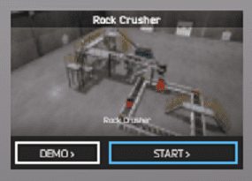
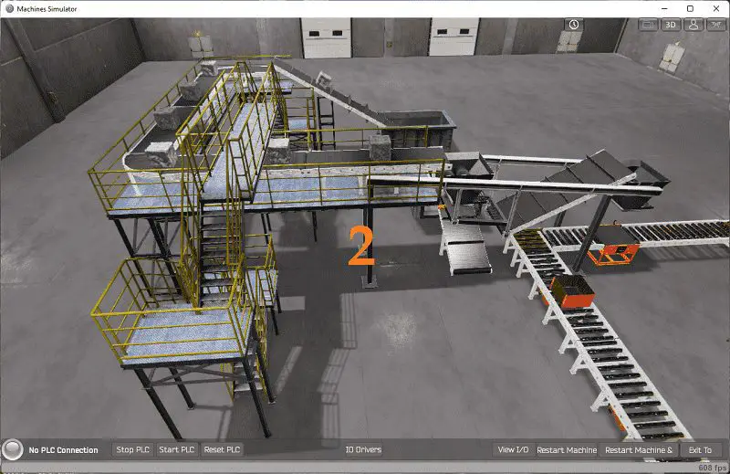
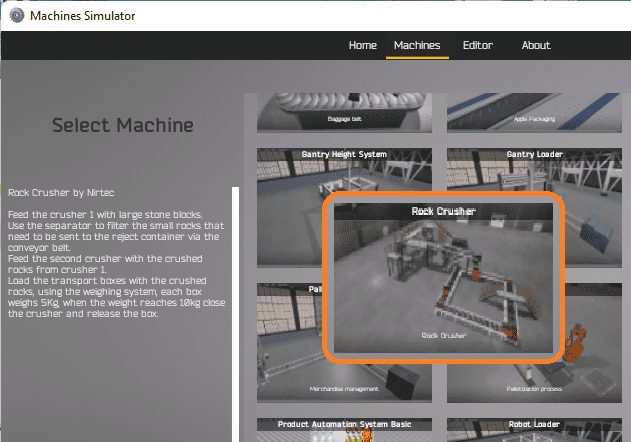 All the available machines will now be displayed. Click on the “Rock Crusher.”
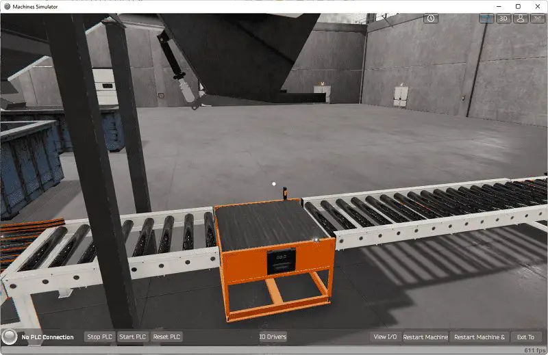
 This is the example that we will be programming. To the left of the screen, information will be displayed on how the rock crusher plant needs to function.
This is printed above.
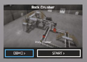
The machine simulator has a demo mode for the built-in machines. This will allow you to watch the operation of the robotic cell. Select the demo mode for the engine loading.
 The rock crusher plant demo mode on the machine simulator will operate, showing you the basics of operation.
Move around the 3D virtual environment. Three icons on the top of the window will allow you to move around this 3D environment. The first icon is the default selection. This will enable you to move around without bumping into the components. The first-person mode will mimic a person in your 3D learning world. The last icon will automatically show you around this virtual environment. Once we understand what must be done, we can move on to the next step in the PLC program development.
Define the Inputs and Outputs: (Step 2 – Rock Crusher Plant EasyPLC)
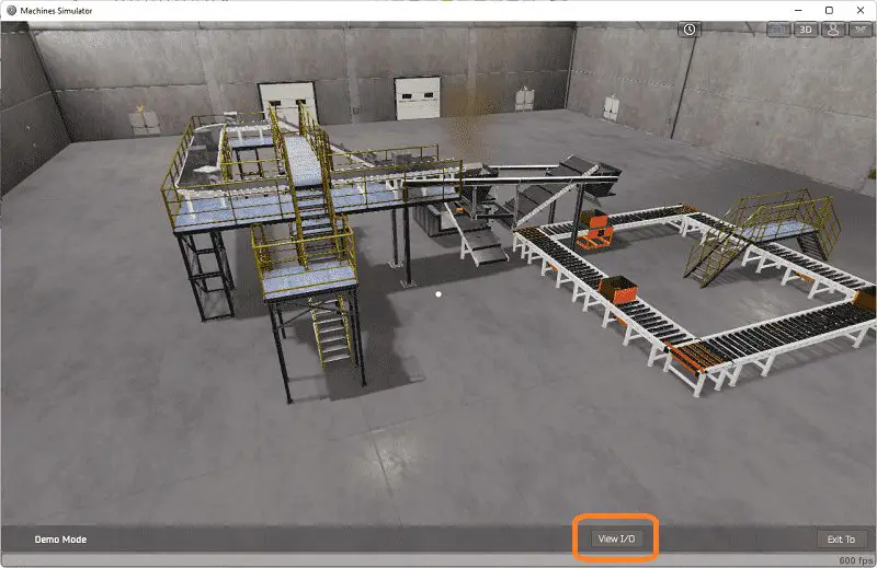
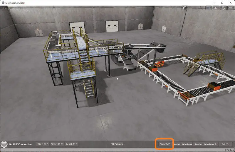
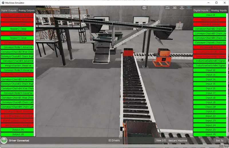
The View IO at the bottom of the machine simulator window will display the inputs and outputs required for this rock crusher plant example. While still in demo mode, you can see the operation of the inputs and outputs.
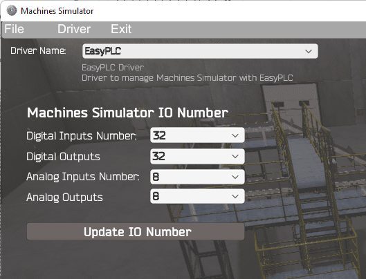
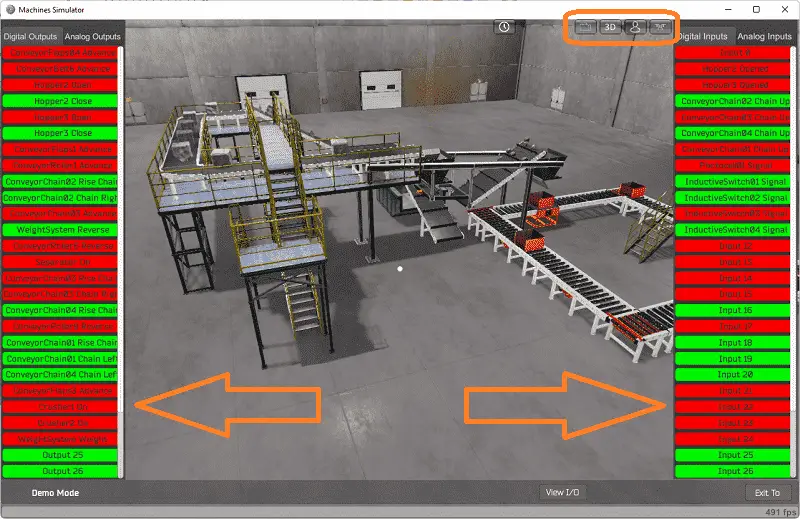 The EasyPLC rock crusher plant example will require 25 digital outputs and 12 digital inputs. It will also need an analog input for the weighing system.
 EasyPLC start mode to manually simulate the rock crusher plant.
 If you are unsure what output or input is doing, start the rock crusher machine in Start mode.
 Select the View IO on the bottom middle of the machine simulator window. You can manually run the robotic cell without any control or PLC connected.
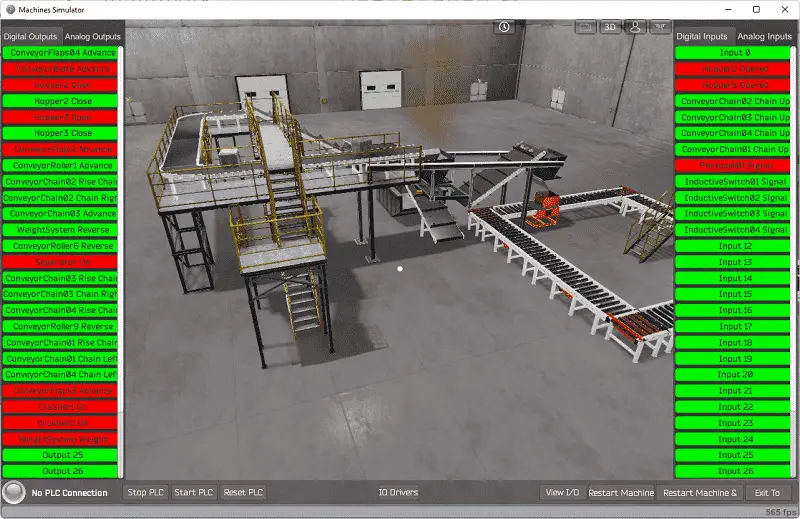 You can now use select and start the rock crusher plant digital outputs on the left side of the screen by clicking on them with the mouse. The right side will show you the corresponding digital inputs. The restart button on the bottom of the machine simulator window will reset the scene back to the start.
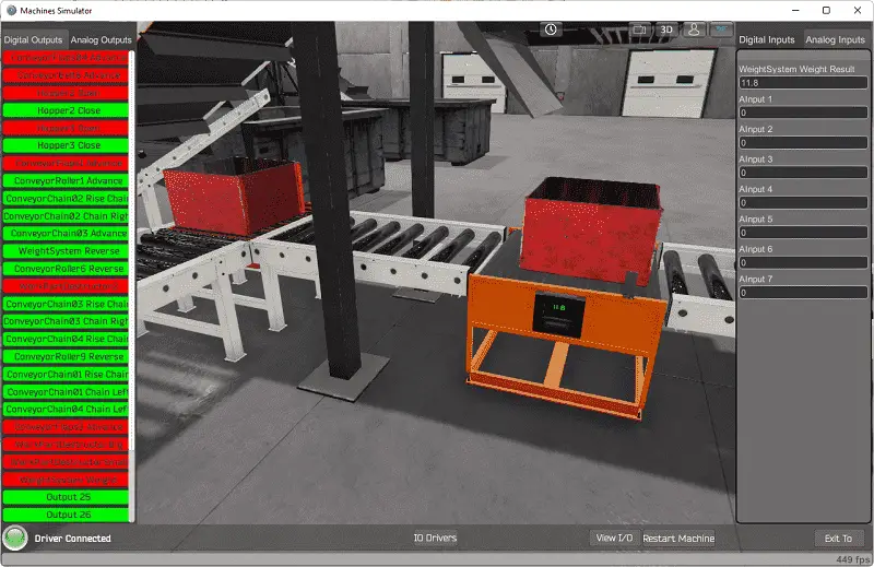
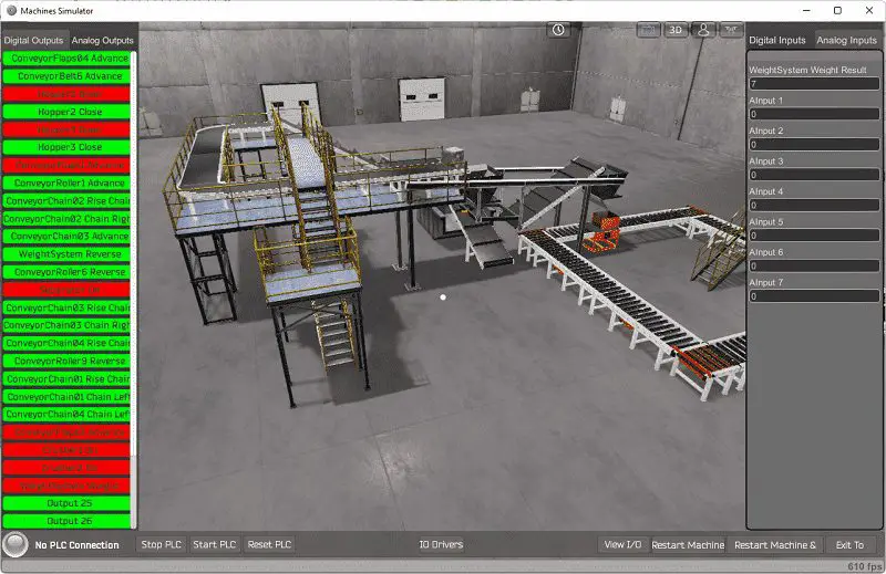 Selecting the analog inputs on the right-hand side will display the weight system analog input.
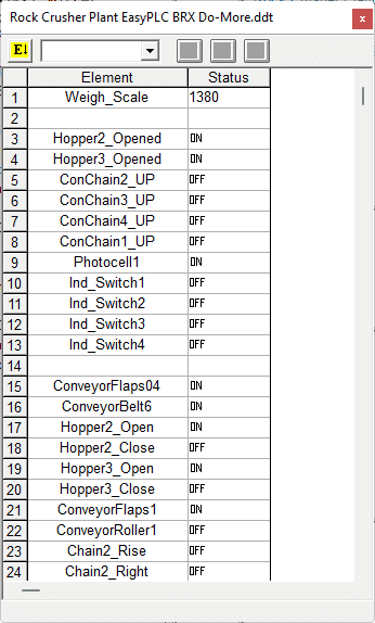
The following table will define the inputs and outputs (IO) and Modbus addresses in the BRX Do-More PLC we will use for this program.
| Digital Type | Description | BRX Do-More PLC Modbus Address | Machine Simulator Modbus Address |
| PLC Output – MS Input | Conveyor Flaps 4 | MI1 – 10001 | 0 |
| PLC Output – MS Input | Conveyor Belt 6 | MI2 – 10002 | 1 |
| PLC Output – MS Input | Hopper 2 Open | MI3 – 10003 | 2 |
| PLC Output – MS Input | Hopper 2 Close | MI4 – 10004 | 3 |
| PLC Output – MS Input | Hopper 3 Open | MI5 – 10005 | 4 |
| PLC Output – MS Input | Hopper 3 Close | MI6 – 10006 | 5 |
| PLC Output – MS Input | Conveyor Flaps 1 | MI7 – 10007 | 6 |
| PLC Output – MS Input | Conveyor Roller 1 | MI8 – 10008 | 7 |
| PLC Output – MS Input | Chain 2 Rise | MI9 – 10009 | 8 |
| PLC Output – MS Input | Chain 2 Right | MI10 – 10010 | 9 |
| PLC Output – MS Input | Chain 3 Advance | MI11 – 10011 | 10 |
| PLC Output – MS Input | Weight System REV conveyor | MI12 – 10012 | 11 |
| PLC Output – MS Input | Conveyor Roller 6 | MI13 – 10013 | 12 |
| PLC Output – MS Input | Separator On | MI14 – 10014 | 13 |
| PLC Output – MS Input | Chain 3 Rise | MI15 – 10015 | 14 |
| PLC Output – MS Input | Chain 3 Right | MI16 – 10016 | 15 |
| PLC Output – MS Input | Chain 4 Rise | MI17 – 10017 | 16 |
| PLC Output – MS Input | Conveyor Roller 9 | MI18 – 10018 | 17 |
| PLC Output – MS Input | Chain 1 Rise | MI19 – 10019 | 18 |
| PLC Output – MS Input | Chain 1 Left | MI20 – 10020 | 19 |
| PLC Output – MS Input | Chain 4 Left | MI21 – 10021 | 20 |
| PLC Output – MS Input | Conveyor Flaps 3 | MI22 – 10022 | 21 |
| PLC Output – MS Input | Crusher 1 On | MI23 – 10023 | 22 |
| PLC Output – MS Input | Crusher 2 On | MI24 – 10024 | 23 |
| PLC Output – MS Input | Weight System WHT | MI25 – 10015 | 24 |
| PLC Input – MS Output | Not Used | MC1 – 1 | 0 |
| PLC Input – MS Output | Hopper 2 Opened | MC2 – 2 | 1 |
| PLC Input – MS Output | Hopper 3 Opened | MC3 – 3 | 2 |
| PLC Input – MS Output | Conveyor Chain 2 UP | MC4 – 4 | 3 |
| PLC Input – MS Output | Conveyor Chain 3 UP | MC5 – 5 | 4 |
| PLC Input – MS Output | Conveyor Chain 4 UP | MC6 – 6 | 5 |
| PLC Input – MS Output | Photocell 1 on weight system | MC7 – 7 | 6 |
| PLC Input – MS Output | Inductive Switch 2 | MC8 – 8 | 7 |
| PLC Input – MS Output | Inductive Switch 1 | MC9 – 9 | 8 |
| PLC Input – MS Output | Inductive Switch 2 | MC10 – 10 | 9 |
| PLC Input – MS Output | Inductive Switch 3 | MC11 – 11 | 10 |
| PLC Input – MS Output | Inductive Switch 4 | MC12 – 12 | 11 |
| PLC Analog Input – MS Analog Output | Weight Scale | MHR11 – 11 | 10 |
Note: The machine simulator will be offset by one on the Modbus Addresses. See the video below for the demo mode and determining inputs and outputs.
See the video below for the demo mode and determining inputs and outputs.
Develop a logical sequence of operation: (Step 3 – Rock Crusher Plant EasyPLC)
A PLC programmer must know how everything about the sequence and operation of the machine before programming. The rock crusher plant is an excellent way to learn to program. A flow chart or sequence table is used to fully understand the process that must be controlled. It must also answer questions like the following:
What happens when electrical power and pneumatic air is lost? What happens when the input/output devices fail? Do we need redundancy?
This step is where you will spend most of your time. Understanding everything about the operation will save you time. It will help prevent you from continuously re-writing the PLC program logic. Knowing all these answers to how the system is to react is vital in developing the PLC program.
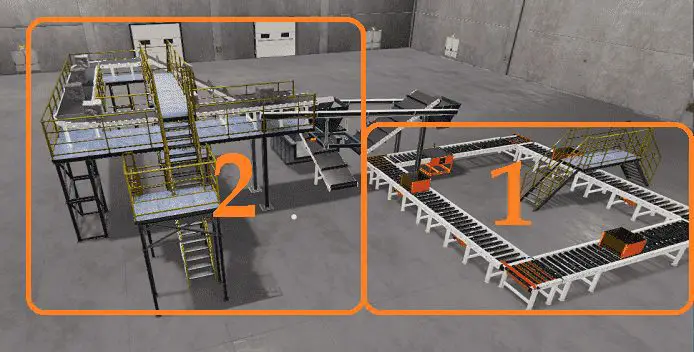
Our rock crusher plant is split into two sections: the box movement on the conveyors and the rock crushers and conveyors themselves. We will walk through the logical sequence of operation.
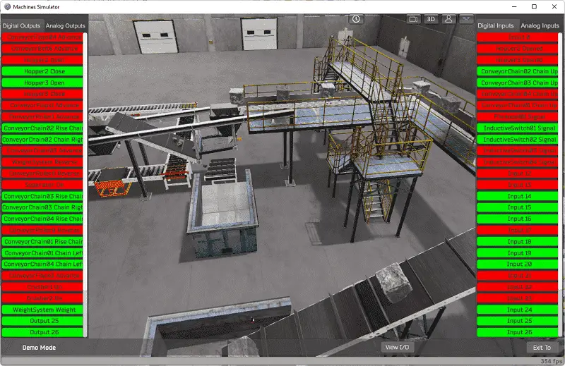
The first section will deal with the boxes and movement around the conveyors. The boxes can be in any position along the conveyor. In the picture above, you see the initial settings of the rock crusher plant.
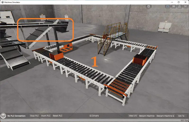 Upon power-up of the PLC (EasyPLC Rock Crusher), we will ensure that the four chain risers are reset. All four conveyors and weight stations run for 10 seconds or until the box is detected by the inductive switches in the conveyor chain corners. We are now sure of each location of the box.
Note: If additional boxes are placed on the conveyor, they must be placed in the corners where we can detect their presence.
If a box is detected on conveyor chain one and conveyor chain two does not have a box and has not risen, then rise conveyor chain 1. When one has risen, run the chain left one and conveyor to move the box to conveyor chain 2. When the box arrives at the conveyor, chain two-stop reset the conveyor chain one rise and conveyor.
If a box is detected on conveyor chain two and the weigh scale sensor does not have a container, or the box is full, then rise conveyor chain 2. When two have risen, run the chain left 2, conveyor and weigh station conveyor to move the box to the weight station.
 When the box arrives at the weigh station and the sensor is activated, stop the weight station belt and lower conveyor belt 2. Allow the conveyor to run for an additional 5 seconds to ensure that any other box is moved along to conveyor chain 3.
Stop the rock crushers and close the doors if a box is complete on the weigh station. If conveyor chain three does not have a box and is not raised, run the weigh scale conveyor and the conveyor. When the package arrives at conveyor chain 3, reset the weigh scale conveyor and conveyor.
If a box is detected on conveyor chain three and conveyor chain four does not have a box and has not risen, then rise conveyor chain 3. When three have risen, run the chain left three and conveyor to move the box to conveyor chain 4. When the box arrives at conveyor chain four, stop (reset) the conveyor chain three rise and conveyor.
If a box is detected on conveyor chain four and conveyor chain, one does not have a box and has not risen, then rise conveyor chain 4. When four have risen, run the chain left four and conveyor to move the box to conveyor chain 1. When the box arrives at the conveyor chain one-stop (reset), the conveyor chain four rises and conveyor.
 The second section will deal with the rock crushers.
If the box is full or there is no box on the weigh system, hopper three will be closed, and the conveyor flaps one will stop.
All the other outputs will be operational.
A PLC programmer must know how everything about the sequence and operation of the machine before programming.
Ask questions or View existing documentation to ensure that you know the logical steps to the machine operation. Writing out what is supposed to happen will help clarify what is required in the PLC program. This is just another method like flow charts and sequence tables.
Develop the BRX Do-More PLC program: (Step 4 – Rock Crusher Plant EasyPLC)
A programmable logic controller (abbreviated PLC) is an industrial computer programmed to perform various automated tasks based on multiple inputs and outputs. They are commonly used in manufacturing, construction, energy distribution, and process control applications. In basic terms: – The ladder logic programming language is used to instruct its function and operations that must be taken when a certain condition arises. Using the information from the previous step, we can now program our BRX Do-More PLC. The BRX Do-More PLC Series will take you through installing the program, communicating to the controller instructions, and addressing the controller.
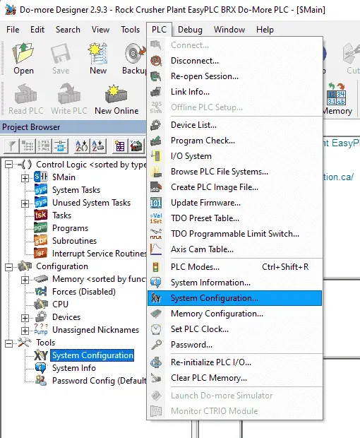 Select the System Configuration… under PLC on the main menu. You can also call this up by selecting system configuration under tools on the project browser.
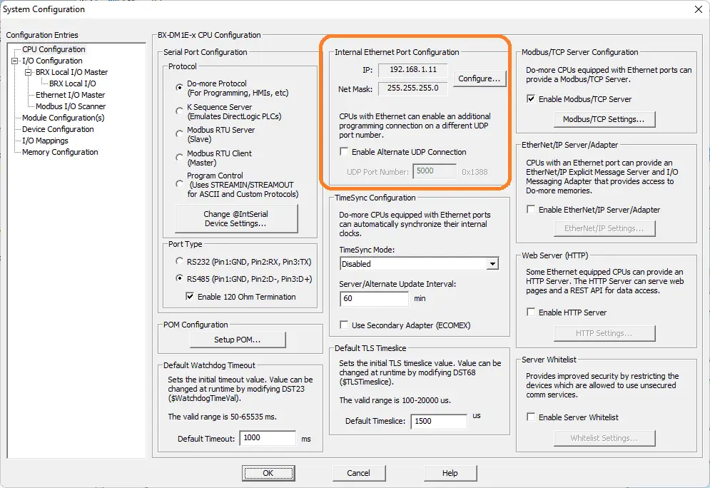 The industrial ethernet port configuration can now be seen or configured by pressing the Configure… button.
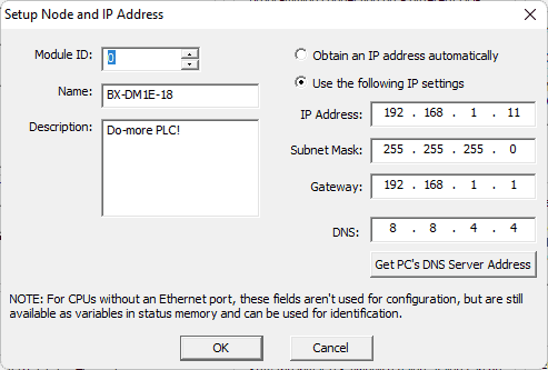 Here are the settings for connecting our BRX Do-More PLC to the Rock Crusher EasyPLC plant simulation. We are using a static IP address for the Ethernet port.
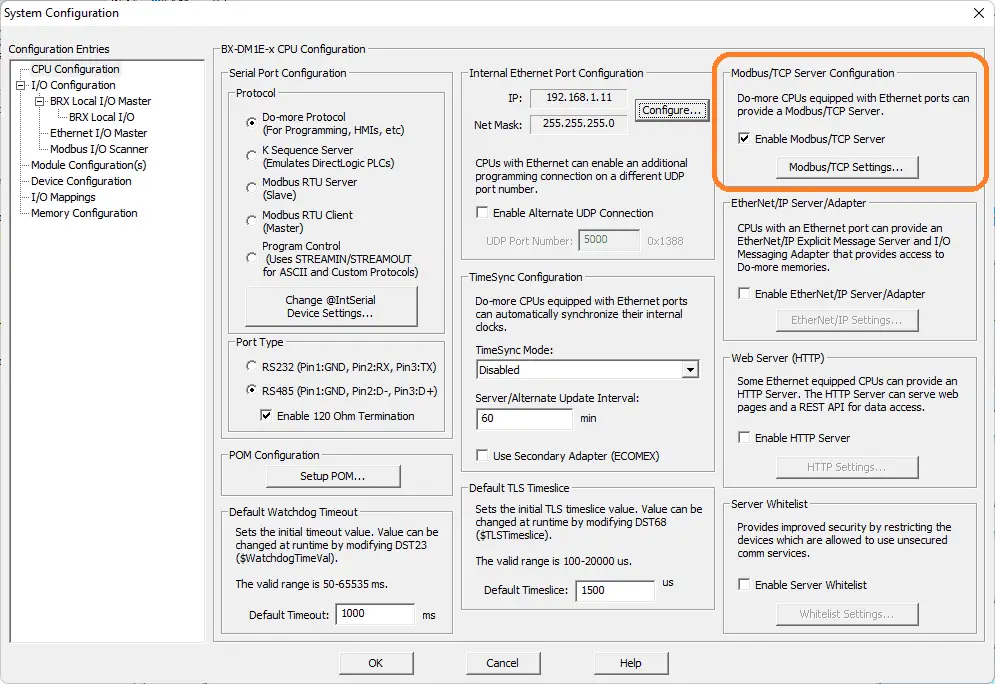 The system configuration page will also show the Modbus TCP Server Configuration. Ensure that this is enabled. Select the Modbus/TCP Settings… button.
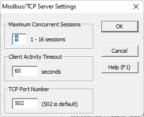 This will show you the Modbus TCP port number, client timeout, and maximum concurrent sessions.
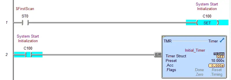
The first rung of the program will set up a timer. This will be used to initialize the system upon a power failure or when the controller is offline.
 The next few rungs will control chain 1 and the conveyor roller 1. This is part of section 1 described above.
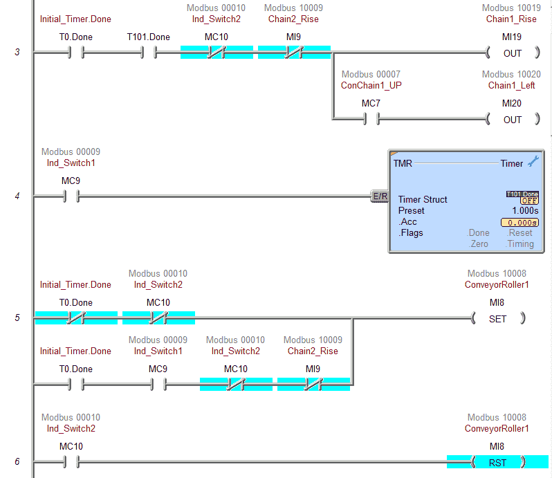 In general, if a box is present at switch 1 and not at switch 2 then the box will be moved to chain 2. The timer is to ensure that the inductive switches are on long enough to ensure the box is in the correct position.
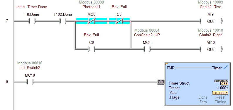 If photocell 1 is not present then the box at chain 2 can be moved to the weight scale.
 Chain 3 will advance the box to the weigh station and/or move the full box to the chain 3 location. The timer is used to continue the chain for 5 seconds after the weigh scale photocell is on. This ensures that any box is fully transferred to the end of the conveyor.
 These rungs will control the weigh system conveyor belt. You can see that it is set when a full box is observed and reset when the photocell sees an initial transition from off to on.
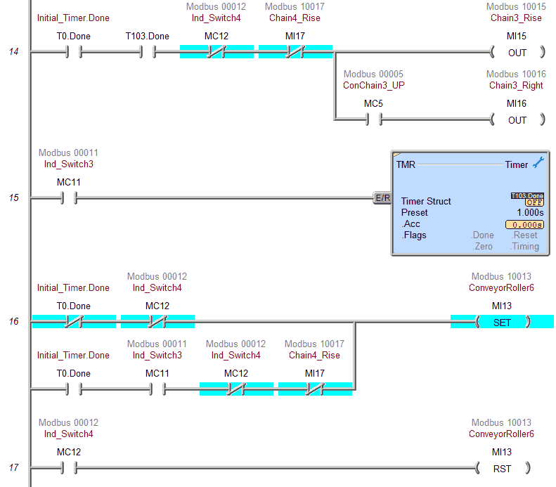 Conveyor roller 6 will move the box from chain 3 to chain 4. You will see common code from previous rungs.
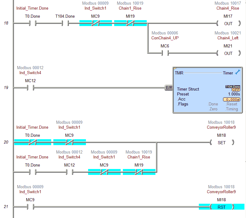 Conveyor roller 9 will move the box from chain 4 to chain 1.
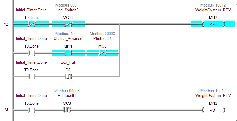
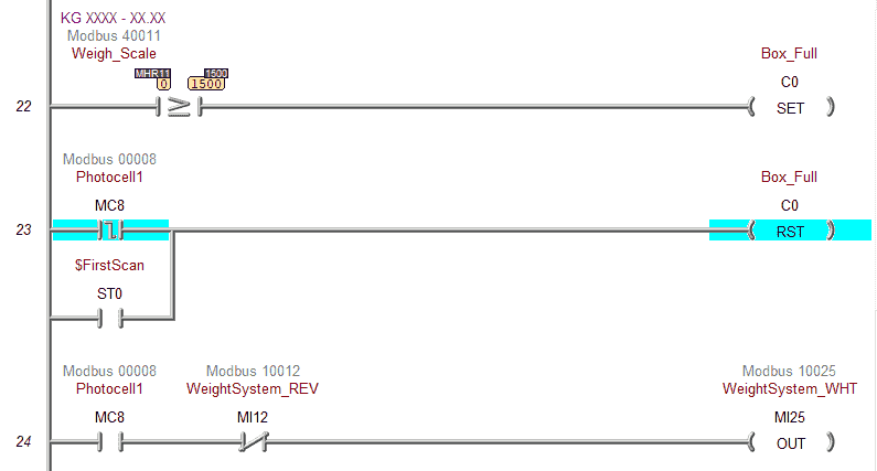 When the weight scale reads greater or equal to 15 KGs then the box full bit is set. The box full bit is reset when photocell 1 transitions from on to off. The weight system bit is on to enable the weighting when the conveyor is not moving and we have the photocell.
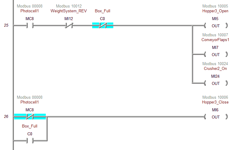 This is from section 2 above in the description. We will turn on the rock crusher 2, conveyor flaps, and open hopper 3 to full the box. Hopper 3 will close when the box is full or when we do not have a box on the weight scale.
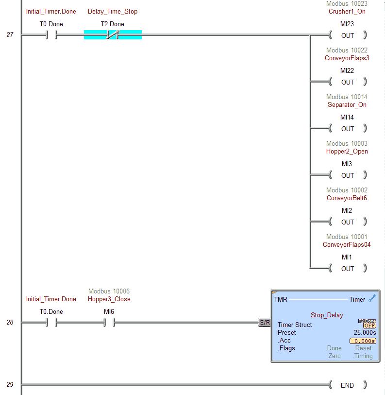 This section will turn on rock crusher 1, conveyor flaps, and belts. If Hopper 3 is closed for more than 25 seconds then the equipment will turn off.
Our ladder logic program is complete. Download the program to the BRX Do-More PLC. Ensure that the controller is in run mode.
Watch the video below to see this PLC program in action on our Rock Crusher EasyPLC.
Test the program: (Step 5 – Rock Crusher Plant EasyPLC)
We will be using Modbus TCP on our BRX Do-More PLC to communicate to the EasyPLC Rock Crusher Machine Simulator.
Call up the rock crusher in start mode.
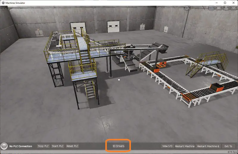 The status of the machine simulator will be along the bottom of the screen. Currently, we have no PLC connected. Select IO Drivers on the bottom middle of the screen.
 The EasyPLC driver is selected by default. Under the driver pull-down menu, select “ModBusDriver.”
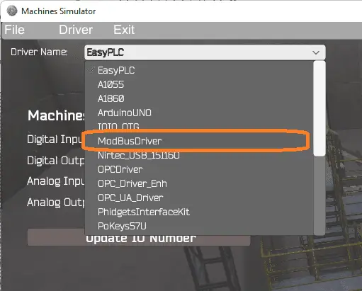 This driver will communicate Modbus TCP (Ethernet) and Modbus RTU (Serial). Select the down arrow on the driver’s name.
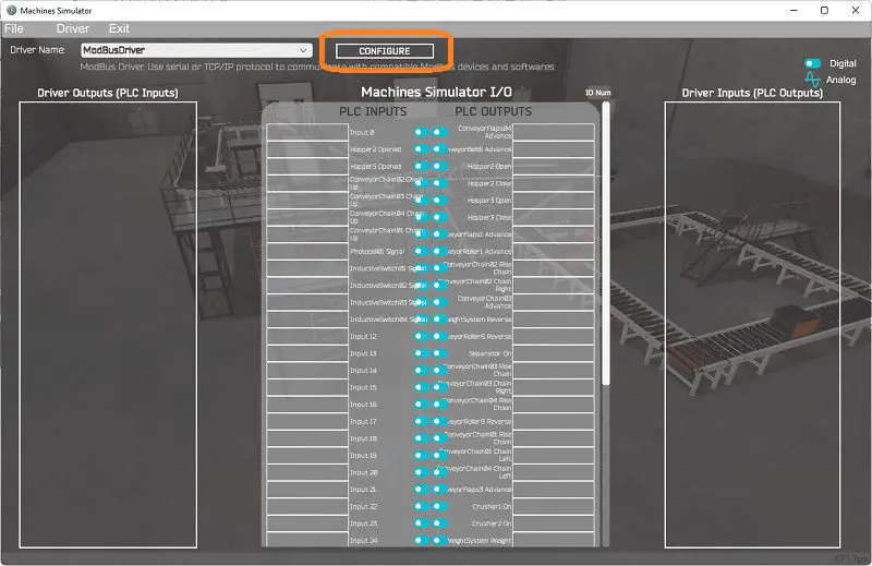 Select the configure button.
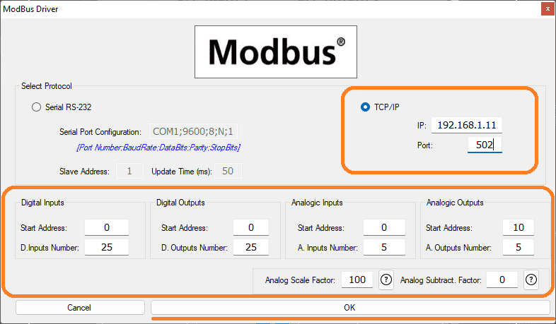 We can now enter the information for our Modbus driver. Select TCP/IP. This means the Ethernet port on the computer will communicate to the PLC.
The digital inputs from MS to the BRX Do-More PLC will be MC1 to MC26. This will start at address 1 because the offset of 1 and the first input are not used. Digital outputs from MS to the Do-More PLC will be MI1 to MI26. This will start at address 1 because the offset of 1 and the first input are not used. The analog values are stored in the MHR area of memory in the Do-More. The analog scale factor of 100 will just multiply the values in MS by a factor of 100. This is to account for the Modbus communication. Our weight scale input will be MHR11. See the table above for the details of the inputs and outputs for our rock crusher EasyPLC plant. Select the OK button.
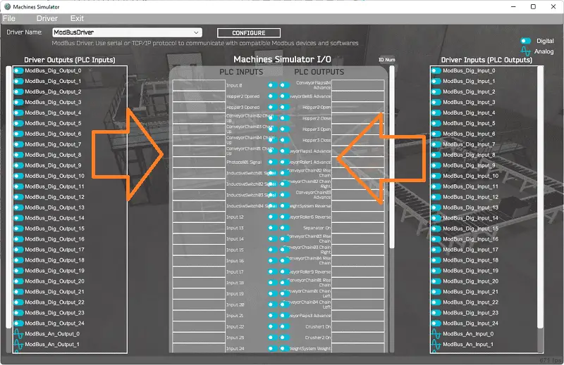 You will now see the inputs and outputs specified for the Modbus driver. We can manually assign the driver outputs to the PLC inputs and the driver inputs to the PLC outputs. However, the automatic assignment works well and will save you time.
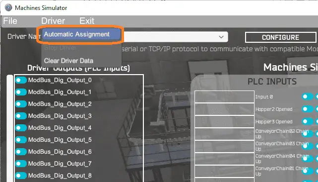 Select Automatic Assignment from the driver option in the main menu.
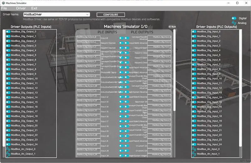 This will automatically assign the PLC IO to the Machine Simulator IO.
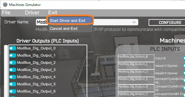 Select start driver and exit from the main menu.
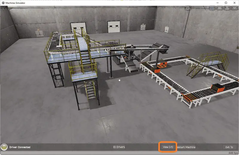 You will see on the bottom left side of the window that the driver communicates to the PLC by the green light. Select view IO to know the input and output status of the machine simulator.
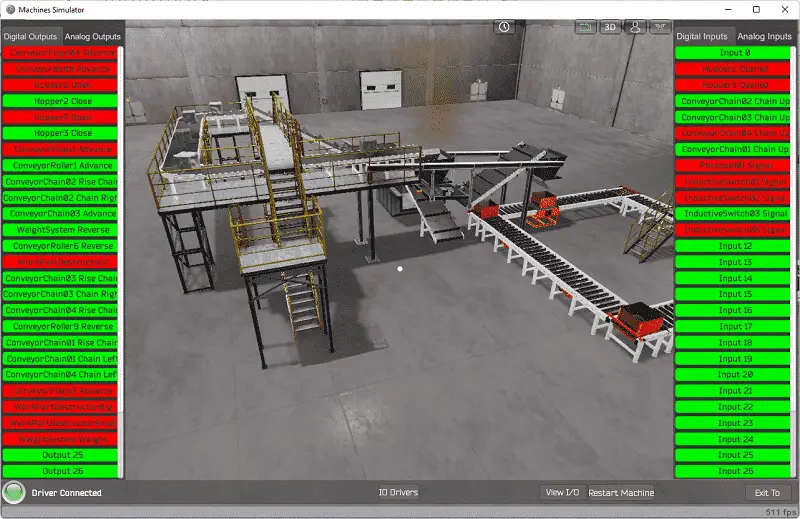
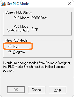 Ensure that the PLC is in run mode. We can see the operation of our EasyPLC Rock Crusher Plant.
 Using the Data View window of the Do-More Designer programming software, we can also watch the inputs and output operations.
Watch the video below to see this on an operation.
You can practice your modification and debug by modifying the Rock Crusher EasyPLC:
– Separate the different sections of the PLC ladder logic to make it more readable.
– Upon a resume, after the line has been shut down, start up the equipment in sequence. This will save the inrush power for the plant simulator.
Let me know how you make out in the comments below.
Download the BRX Do-More PLC sample program for the EasyPLC rock crusher here.
Watch the video below to see the five steps of program development applied to the rock crusher plant. The machine simulator is one of the best applications to help you learn PLC programming.
EasyPLC Software Suite is a complete PLC, HMI, and Machine Simulator Software package. This PLC learning package includes the following:
Easy PLC – PLC Simulation allows programming in Ladder, Grafcet, Logic Blocks, or Script.
HMI System – Easily create a visual human-machine interface (HMI)
Machine Simulator – A virtual 3D world with real-time graphics and physical properties. PLC programs can be tested using the EasyPLC or through other interfaces. (Modbus RTU, TCP, etc.)
Machine Simulator Lite – Designed to run on Android Devices.
Machine Simulator VR – Virtual Reality comes to life so you can test, train or practice your PLC programming.
Purchase your copy of this learning package for less than USD 75 for a single computer install or less than USD 100 to allow different computers.
Receive 10% off the price by typing in ACC in the comment section when you order. http://www.nirtec.com/index.php/purchase-price/
Learn PLC programming the easy way. Invest in yourself today.
Watch on YouTube: Rock Crusher Plant EasyPLC BRX Do-More
If you have any questions or need further information, please contact me.
Thank you,
Garry
If you’re like most of my readers, you’re committed to learning about technology. Numbering systems used in PLCs are not challenging to learn and understand. We will walk through the numbering systems used in PLCs. This includes Bits, Decimal, Hexadecimal, ASCII, and Floating Point.
To get this free article, subscribe to my free email newsletter.
Use the information to inform other people how numbering systems work. Sign up now.

The ‘Robust Data Logging for Free’ eBook is also available for free download. The link is included when you subscribe to ACC Automation.