Sequential Function Chart (SFC) is a graphical programming language that can be used in Arduino Opta PLCs. It can be used to program sequential control systems in industrial automation applications. It is a part of the IEC 61131-3 standard and is commonly used in programmable logic controllers (PLCs) and other industrial control systems. SFC allows programmers to create complex control sequences by breaking them down into small, manageable steps. It consists of a series of interconnected steps, each containing actions, conditions, and transitions. These steps are executed in a predetermined order, based on the conditions and transitions defined in the chart. SFC is particularly useful for complex, multistage control systems, such as manufacturing and process control applications.
The Arduino Opta PLC supports sequential function chart programming as one of the five programming languages in the IEC standard and Arduino C++. This lets you choose the programming language that best suits your needs and preferences. Arduino C++ is a widely used programming language in the Arduino community and offers a vast library of functions and resources. Whether you program in structured text, Arduino C++, or any other language, the Arduino Opta PLC provides a powerful platform for developing automation and control applications. Its versatility and compatibility with different programming languages make it popular among developers and engineers.
In the following sections, we will explore how to start a new project in the Arduino Opta PLC and how to map the physical I/O in the PLC. These steps are essential for setting up the foundation of your project and ensuring proper communication between the PLC and the external devices.
The entire Arduino Opta IoT PLC Series is located here.
Previously in this series, we have discussed the following:
Opta Introduction Video
Arduino Opta IoT PLC Cutting Edge Hardware – Video
Arduino Opta Software Installation – Video
Arduino Opta IoT PLC Quick Start Ladder Logic – Video
Easy Steps to Establish Communication between Arduino Opta IoT PLC – Video
Arduino PLC IDE Workspace: Unleash the Power! – Video
Programming with the Arduino OPTA PLC – Ethernet Port – Video
Arduino OPTA PLC – Ladder Diagram First Program – Video
Arduino OPTA PLC – Instruction List (IL) First Program – Video
Arduino OPTA PLC – Function Block Diagram (FBD) – Video
Arduino OPTA PLC – Structured Text (ST) – Video
Note: A post is usually associated with each video. This will provide additional details and links discussed.
Start a new project
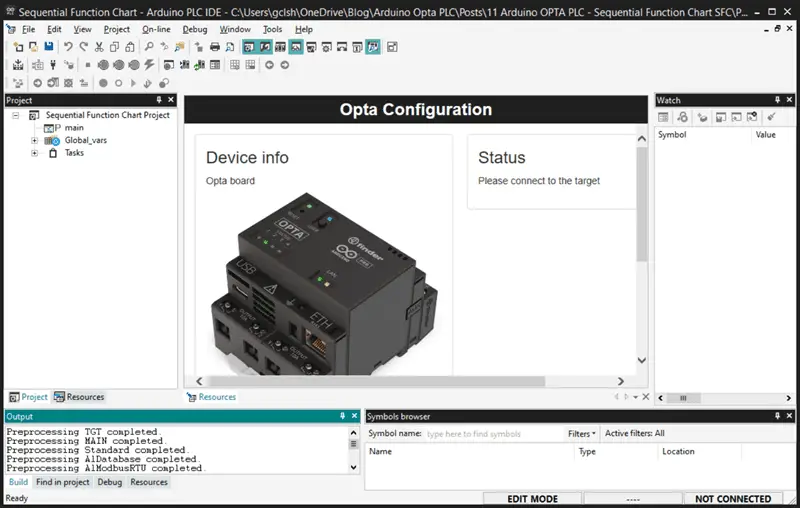
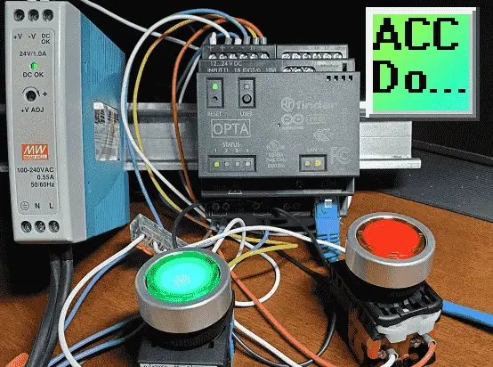
Our project will create a stop-stop circuit with two lighted pushbutton switches using sequential function chart (SFC) programming. When the green LED pushbutton is selected, the green LED light will turn on. This will remain on until the red-led push button is selected. When the green LED is on, the red LED is off, and vice versa. The CPU green LED will be on if the Arduino OPTA PLC is executing its program. Open your computer’s Arduino PLC Integrated Development Environment (IDE) software.
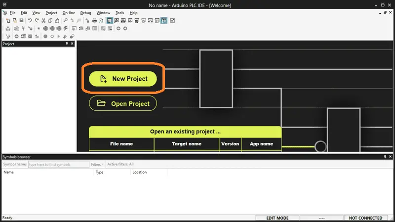
Start a new project by selecting “New Project” on the main software screen.
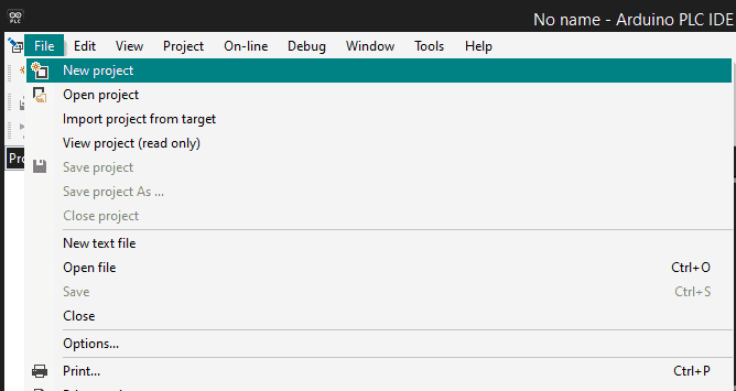
A second method of starting a new project is to select “New Project” from the main menu | File.
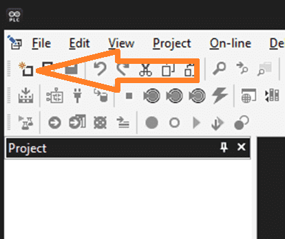
The third method is to choose the icon for a new project.
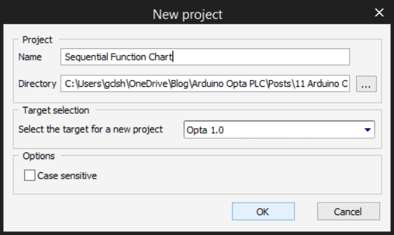
The new project window will now be displayed. Enter the name of the project in the dialog box. This will be the name of the Program stored on your drive. We will leave the default directory as it is. Ensure that the Opta 1.0 PLC is selected for the target. Select OK.
This will now create and save your program file for the Opta PLC.
Mapping physically I/O in the OPTA PLC
The Opta has physical inputs and outputs we must map before using them in our project. In the workspace window, select the Resources tab at the bottom. Under local IO mapping, you will see all of the physical inputs and outputs on this controller.
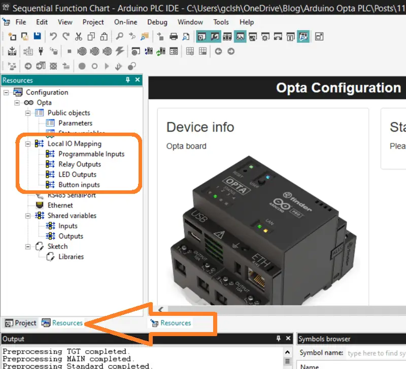
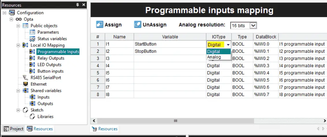
Select programmable inputs. The programmable inputs mapping will be displayed. We can assign a variable to each input we intend to use in our structured text program. Under IO type, we can select digital (default) or analog. The analog resolution can also be selected for the inputs.
Select relay outputs that display the relay outputs mapping.
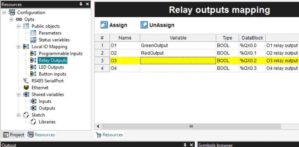
We can once again assign a variable to the relays that we will use in our sequential function chart SFC program.
Select LED Outputs, which display the LED outputs mapping.
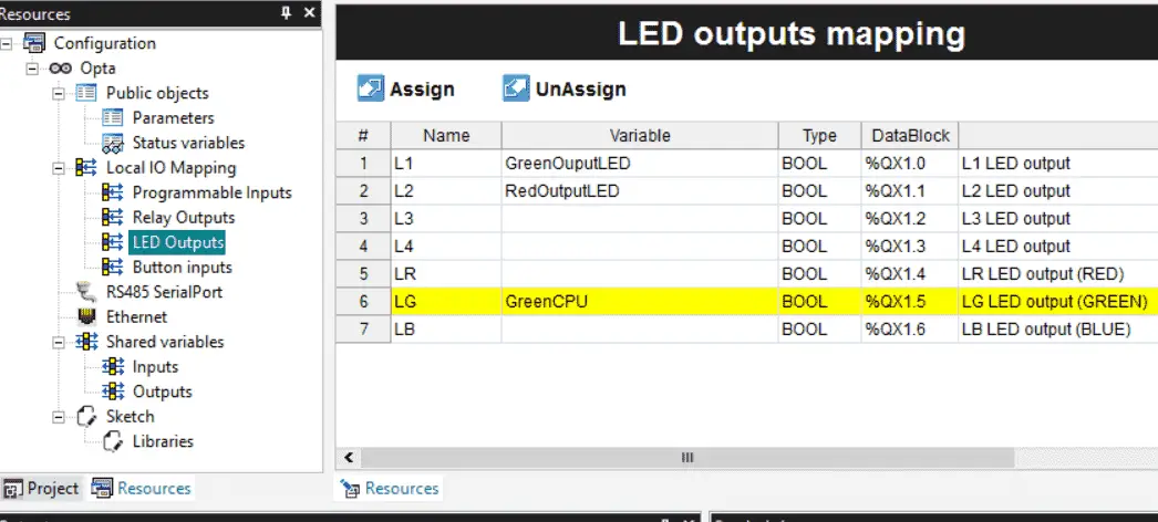
These are the status lights on the Opta CPU unit. We will make these represent the relays in our Program. Assign a variable name to the LED output that we will use. The Opta PLC also has a front LED that can be different colors. We will assign the green output to indicate that the Opta PLC code is scanning.
Now that all of our mapping is complete, we can save the Program using the icon on the main page. We can also save the Program using the main menu | File | Save Program.
Wiring the Inputs and Outputs
We can now physically wire the two lighted pushbutton switches to the inputs and the LEDs of these switches to the outputs.
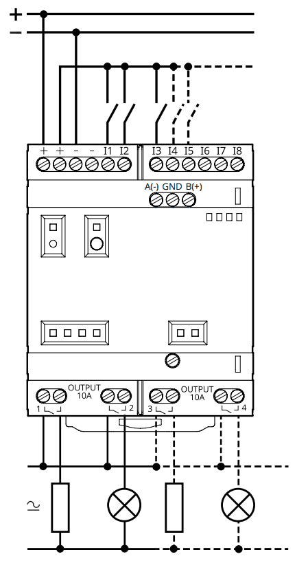
Here is the wiring diagram of the Arduino OPTA PLC.
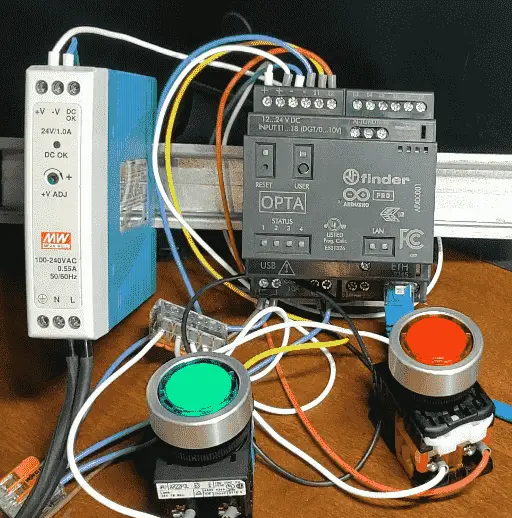
The positive 24-volt DC signal is wired to one side of the green normally open switch contact. It is also wired to one side of the red normally closed switch contact. The other side of the switches are wired to input 1 and 2, respectively. The positive 24-volt DC signal is wired to one side of the switch lamps. Relay outputs are provided on the Arduino OPTA PLC. The other side of the switch LED lights are wired to one side of the relay for each switch. Green will be output one, and red will be output two. The other side of the relay output contacts of the PLC will be wired to the 0-volt DC signal. This completes the wiring of the PLC.
Tasks in the Opta PLC
To access the tasks in your project, navigate to the project tab and locate the tasks folder. You will see the list of IOs we have just mapped for this project.
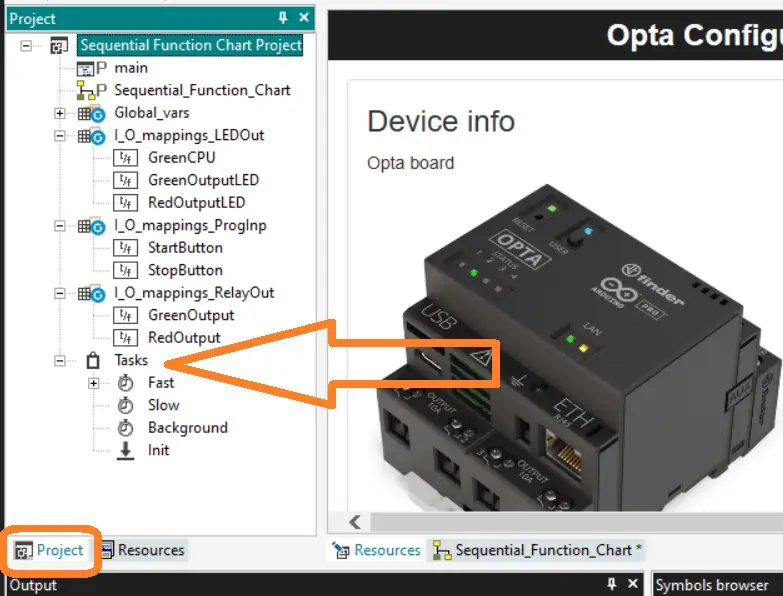
Expand the folder by clicking on the plus sign next to it. The tasks are categorized into Fast, Slow, Background, and Init. To configure the tasks, right-click on any four task folders and select task configuration.
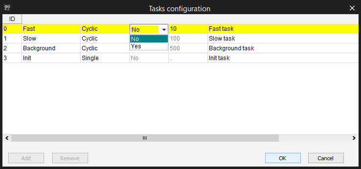
Your programs will be executed within the designated task folders. The Fast Task folder will execute your programs cyclically every ten milliseconds. (100 times per second) This can be changed by changing the set period to yes. You can then enter a value in the period column in milliseconds. The majority of programs will be placed in this folder. The Slow and Background task folders will also scan cyclically. They are both set at a fixed period of 100 and 500 milliseconds. (10 times per second and two times per second) These tasks are ideal for functions like math equations, etc. The Init or Initialize task folder sets variables or conditions in the PLC after it powers up. It will run for a single scan. Select OK to close the task configuration window.
Starting a new Sequential Function Chart SFC Program
Select | Project | New Object | New Program from the main menu to start a new program.
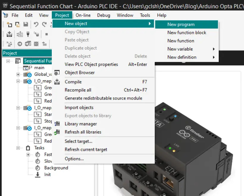
You can also do this by right-clicking on the project name and selecting the new Program under the add heading. The new program window will be displayed.
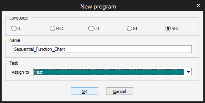
We will use a sequential function chart (SFC) in our example.
Select ST. Name and assign the new Sequential Function Chart program to the fast task folder. The program name cannot have spaces.
Select OK.
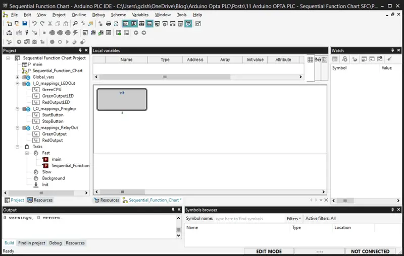
Our new SFC program will now be displayed in the work area. This Program also appears under the fast task folder and the project as an SFC symbol.
In the help menu, you will find all of the operators and their parameters that can be used for this structured text programming. Save the Opta PLC program.
Programming our Sequential Function Chart (SFC)
Sequential Function Chart (SFC) is a high-level programming language widely used in programmable logic controllers (PLCs). It is a graphical language used to write programs for industrial control systems. One of the advantages of SFC is that it breaks down and organizes your code, making it a popular choice for many engineers and developers. This simple task of viewing your logic in smaller, sequenced steps makes it ideal for troubleshooting and maintaining the PLC code.

Generative artificial intelligence (AI) can be used to create sample programs for SFC. This can break your program into simple steps, making it an ideal candidate for machine learning algorithms. ChatGPT is a powerful AI tool that can be used to generate code in SFC for a Start Stop circuit.
We can ask ChatGPT to “Write a start-stop circuit using SFC.”
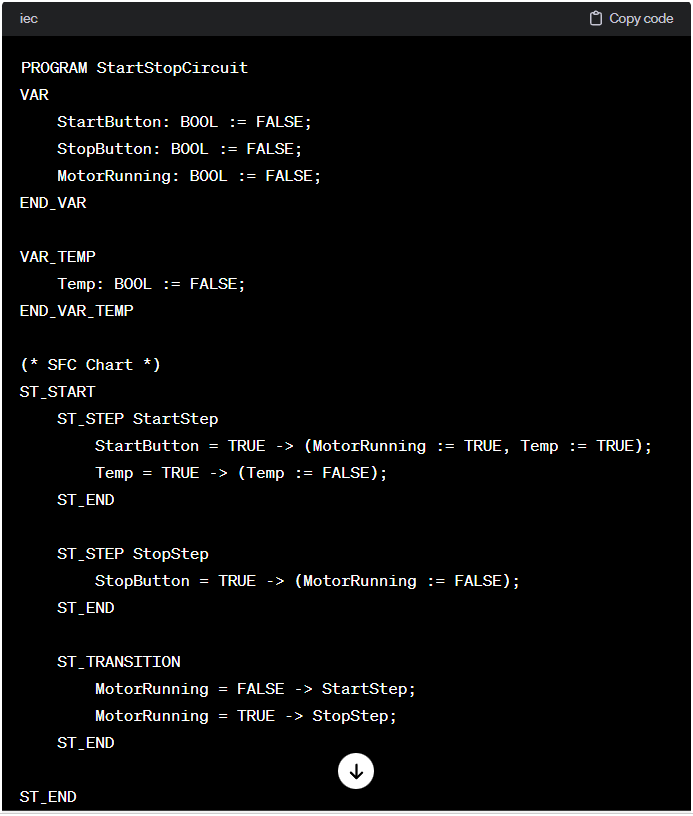
Sure, I can provide you with a simple example of a start-stop circuit using a Structured Function Chart (SFC). In SFC, you can represent the control flow using steps and transitions. Here’s a basic example in SFC for a start-stop circuit:
Explanation:
StartButton,StopButton, andMotorRunningare variables representing the state of the start button, stop button, and the motor, respectively.- The SFC chart has two steps:
StartStepandStopStep. When theStartButtonis pressed, the motor is set to running (MotorRunning := TRUE). TheTempvariable is used to ensure that the transition only occurs once when theStartButtonis pressed. - The
StopStepis triggered when theStopButtonis pressed, and it setsMotorRunningtoFALSE. - The transitions between steps are defined based on the state of the
MotorRunningvariable. If the motor is not running, theStartStepis activated. If the motor is running, theStopStepis activated.
This is a basic example, and in a real-world scenario, you might have additional conditions, safety checks, or other features depending on the requirements of your application. Adjustments may be needed based on the specific behavior you’re looking for in your start-stop circuit.
The response from AI can give us an understanding of how our sequential function chart (SFC) works. It will split up our task into smaller steps.
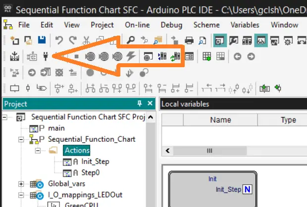
Looking at the Arduino PLC IDE software, we will enable the SFC toolbar.
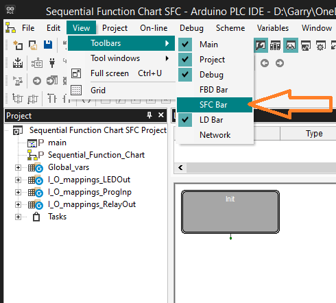
On the main menu, select View | Toolbars | SFC Bar.
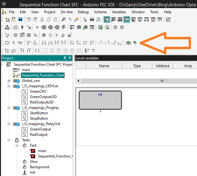
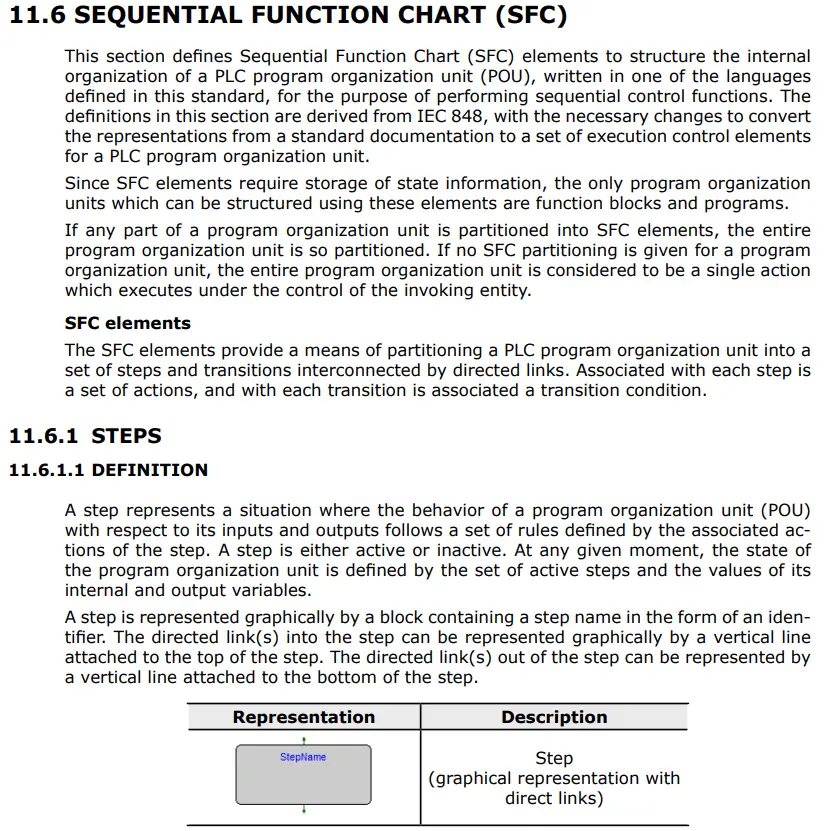
SFC programming consists mainly of steps and transitions. Steps will include actions that must be taken. This can be as simple as turning on an output or creating an entire program. Actions can be written in any of the five PLC programming languages that we have covered in this Arduino OPTA PLC series. Transitions are used to transfer control from one step to the next.
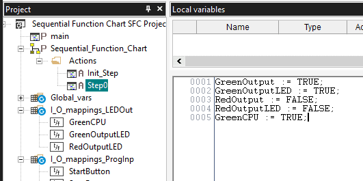
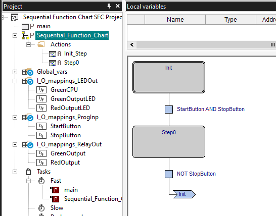
An Init (Initialize) step must be present in every SFC program. This is the reason that we see this appear in our default program. Our initial step will turn on the RedOutput, RedOutputLED, and GreenCPU. It will also turn off the GreenOutput and GreenOutputLED.
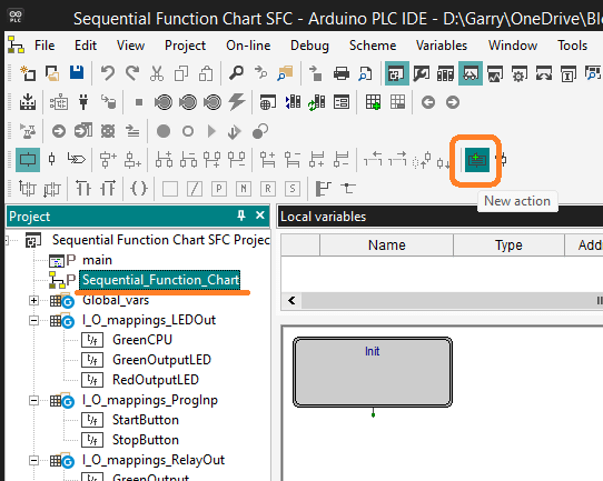
Under the Project tab, select Sequencial_Function_Chart. This will enable the new action to be selected on the SFC bar. Select New Action.
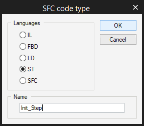
We will select ST as the Language and name our step Init_Step. Select OK.
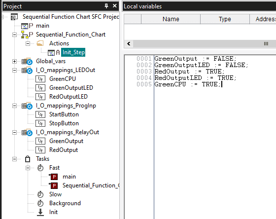
Under the Sequential_Function_Chart, we now have a folder with actions. Expand this, and you will see our Init_Step that we just specified. Double-click this and enter our initial parameters.
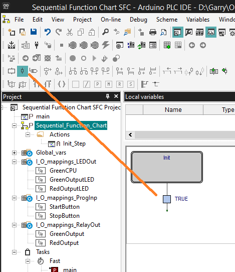
Select the transition icon on the SFC bar. Now click on the work area under the Init step. This will add a transition to our circuit. Double-click on this transition.
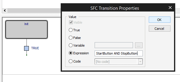
Since our stop button is wired normally closed, we will put in the expression that we need the start and stop buttons. This ensures that the stop button is not being pressed when we try to start. Select OK.
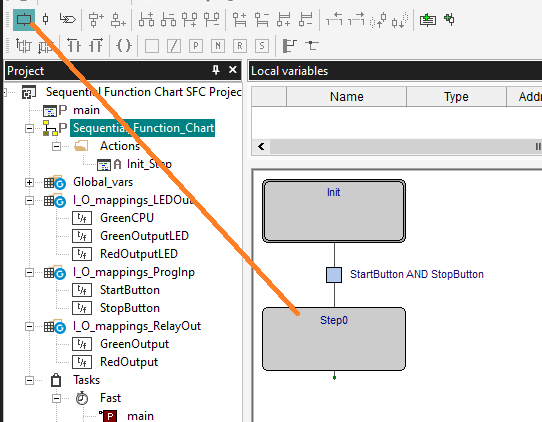
Select the new step on the SFC bar. Under the transition, click the work area to place this Step0. Select the new action from the SFC bar. We will use the ST language again and call this Step0.
We will now enter the values we want for our outputs based on the press of our start button.
Select the Sequential_Function_Chart diagram again and add another transition under Step 0. Double-click on this transition.
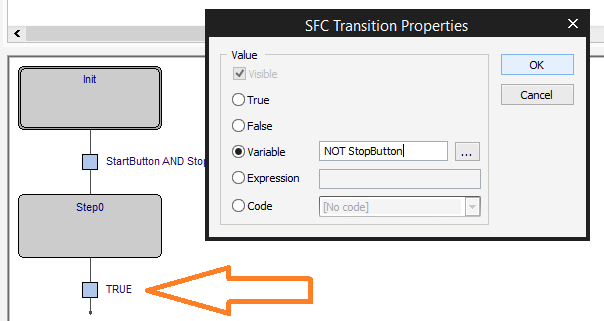
Enter the variable NOT Stop Button. This will indicate when the stop button has been pressed because it has been wired normally closed. Select OK.
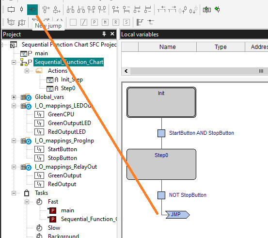
Select New Jump from the SFC bar. We will position this under the last transition. Double-click on this jump connector.
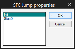
Select the Init step for this jump. It means that after the stop button is pressed, the program will return to the Init step of the program. Select OK.
We now have the basic structure and sequence for our SFC program. However, we have not specified the actions to be taken at each step. Double-click on the Init step. The SFC Action Properties windows open up for the step.
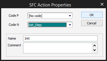
Code P means pulse. The action is executed only once per step activation; regardless of the number of cycles, the step remains active.
Code N means Non-stored. The action is executed as long as the step remains active.
In our case, we will use Code N on our Init_Step logic. Select OK.
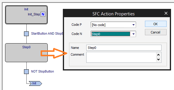
Double-click on Step 0 and use Code N as well on our Step 0 logic. Select is OK.
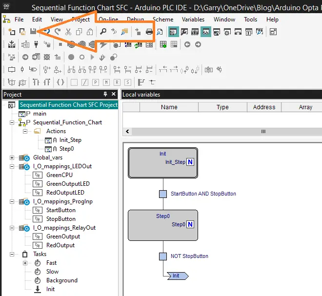
Our SFC OPTA PLC program is complete.
Save the Program by using the icon on the main menu or selecting “Save project” from the main menu | File.
Download the SFC program to the Opta PLC.
Select setup communication from the main menu | On-Line. In the device link manager window, select Modbus TCP and then select activate.
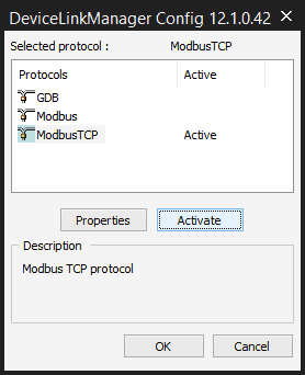
Select properties.
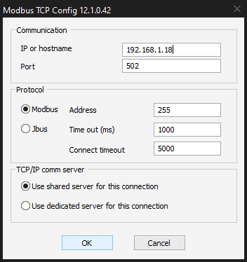
We can now enter the IP address we established in the following post. Programming the Arduino OPTA PLC – Ethernet Port Our communication method with the OPTA PLC is now set.
Select the connect button.
We will now see that our computer is connected to the Opta PLC controller.
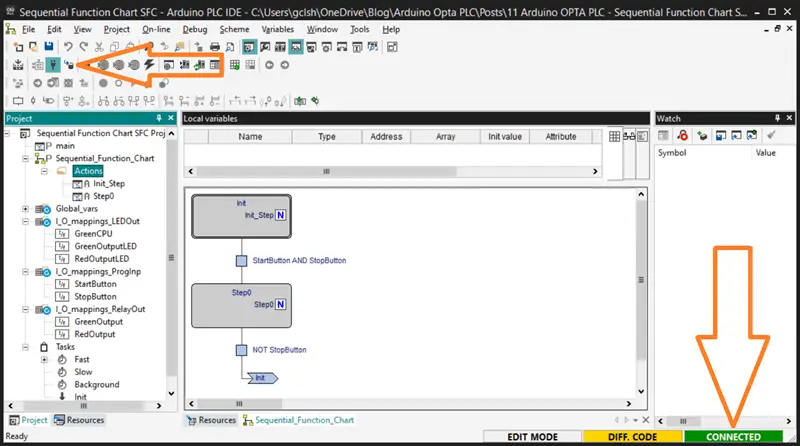
Select the download icon on the main menu. Since we didn’t compile the project first, the PLC IDE prompts us before downloading. Select Yes.
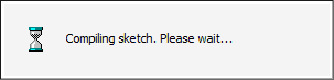
The output window will display the status of the download operation.
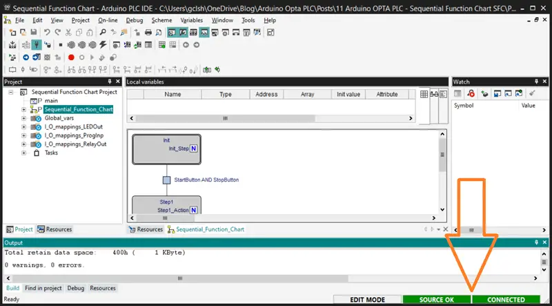
When this has finished, the bottom right side of the software will show you that the PLC IDE and controller programs are the same.
Monitoring the SFC Logic and Variables
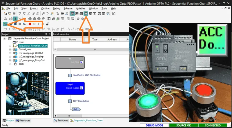
Select the live debug mode on the main screen. This will show you the status of the steps and transitions on the SFC (Sequential Function Chart).
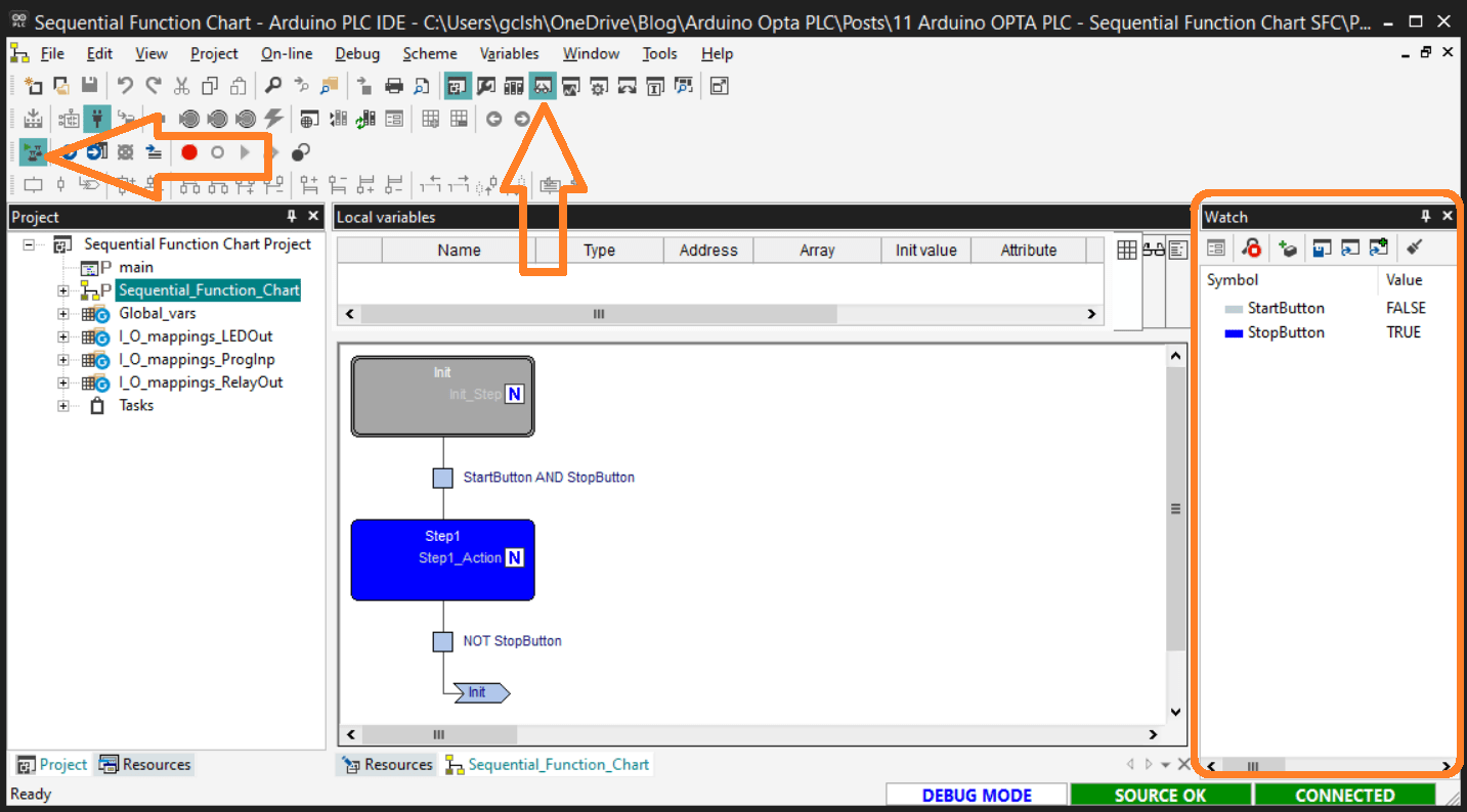
Select the watch icon on the main menu. This will display the watch window. We can enter and select the variables (tags) we want to monitor.
Watch the video below to see how to create structured text programs with the Arduino Opta IoT PLC.
Arduino Opta PLC – IoT and Industry 4.0 Enabler
Arduino Opto IoT PLC Series
Opta – Frequently Asked Questions (FAQ)
Finder OPTA 8A Series – Tutorials
Datasheet
Quickstart Sheet
Arduino Opta Hardware
Arduino PLC IDE
Arduino Software Download Page
(Arduino IDE, PLC IDE, PLC IDE Tools)
Watch on YouTube: Arduino OPTA PLC – Sequential Function Chart (SFC)
If you have any questions or need further information, please get in touch with me.
Thank you,
Garry
If you’re like most of my readers, you’re committed to learning about technology. Numbering systems used in PLCs are not challenging to learn and understand. We will walk through the numbering systems used in PLCs. This includes Bits, decimals, Hexadecimal, ASCII, and Floating points.
To get this free article, subscribe to my free email newsletter.
Use the information to inform other people how numbering systems work. Sign up now.

The ‘Robust Data Logging for Free’ eBook is also available for free download. The link is included when you subscribe to ACC Automation.