The Machine Simulator (MS) is part of the EasyPLC software suite. It has many built-in machines that are used to show different programming techniques. The robotic cell example is one of these machines. This will demonstrate a sequencer example. In this case, an engine is lifted and placed onto a rack. The logic will step through various steps to perform the task.
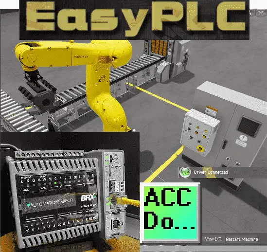 We will be using a BRX Do-More PLC and the Do-More Designer programming software to program this EasyPLC machine simulator engine loader of the robotic cell. This will be done using Modbus TCP (Ethernet) for communications. The program will allow you to start, stop and jog the sequencer. Modifications of the EasyPLC Robotic Cell will include controls for this operation. Using the five steps for program development, we will show how this sequencer is programmed. Let’s get started.
Learn PLC programming the easy way. See below how to receive a 10% discount on this already cost-effective learning tool. Invest in yourself today.
Previously we have done the following:
Easy PLC Installing the Software – Video
EasyPLC Software Suite – Quick Start – Video
Click PLC – Easy Transfer Line Programming – Video
Productivity PLC Simulator – Chain Conveyor MS – Video
Do-More PLC – EasyPLC Box Selection Program – Video
Click PLC EasyPLC Gantry Simulator – Video
Click PLC Simple Conveyor EasyPLC – Video
EasyPLC Paint Line Bit Shift – BRX Do-More PLC – Video
Click PLC – EasyPLC PLC Mixer Programming – Video
Click PLC EasyPLC Warehouse Stacker Example – Video
– Operation Video
EasyPLC Machine Simulator Productivity PLC Robotic Cell – Video
EasyPLC Simulator Robotic Cell Click PLC – Video
Define the task: (Step 1 – Easyplc Robotic Cell)
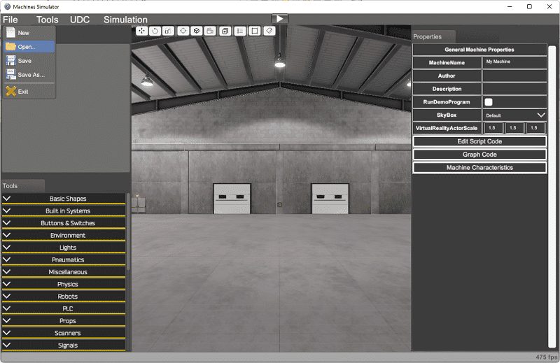
The first step of PLC program development is determining what must be done. Start the EasyPLC Machine Simulator (MS). Select the start button on the main page or select machines from the main menu at the machines simulator window.
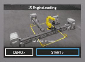
 All the available machines will now be displayed. Click on the “13 Engine Loading”. This is the example that we will be programming. To the left of the screen, information will be displayed on what the machine needs to do and the inputs and outputs required for the program.
This system uses:
1 Robot
2 Conveyor Lines
2 Conveyor Stops
2 Inductive Switches
1 Beacon Light
Use the industrial robot to load the engine blocks into the pallets. Manage the conveyors and stops to place the parts in their positions. The robot loads the engine block into the pallet. Once loaded, release the pallet. The robot moves with PLC digital IO signals.
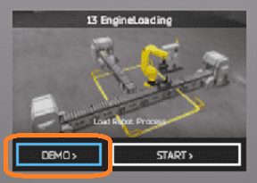 The machine simulator has a demo mode for the built-in machines. This will allow you to watch the operation of the robotic cell. Select the demo mode for the engine loading.
 The demo mode will show you the basics of the operation of the load robot process.
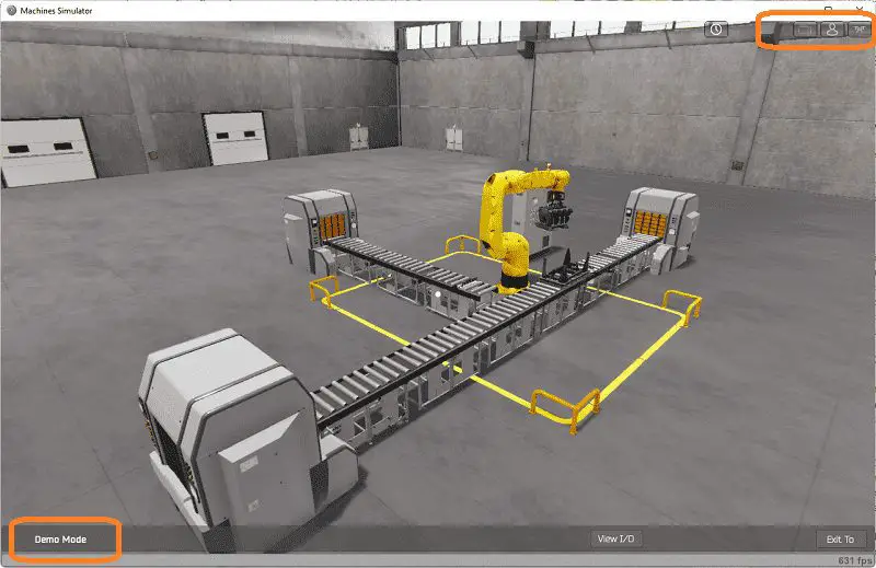
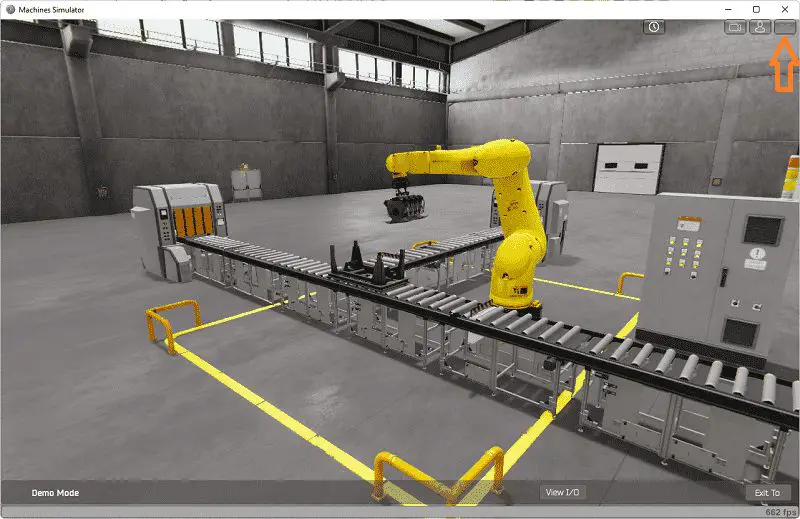 Move around the 3D virtual environment. There are three icons on the top of the window that allows you to move around this 3D environment. The first icon is the default selection. This will enable you to move around without bumping into the components. The last icon will automatically show you around this virtual environment. The first-person mode will mimic a person in your 3D learning world. Once we understand what must be done, we can now move on to the next step in the PLC program development.
EasyPLC Factory Editor Robotic Cell Additions
We will be modifying the “13 Engine Loading” in the EasyPLC machine simulator. The first step is to make a backup of the existing machine. Watch the video below to see how additions are made to the EasyPLC machine simulator.
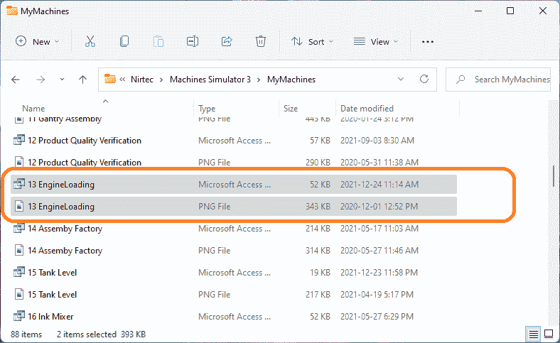 In the drive that EasyPLC Software Suite was installed. Go to Nirtec \ Machines simulator 3 \ My Machines. Copy the picture and program file.
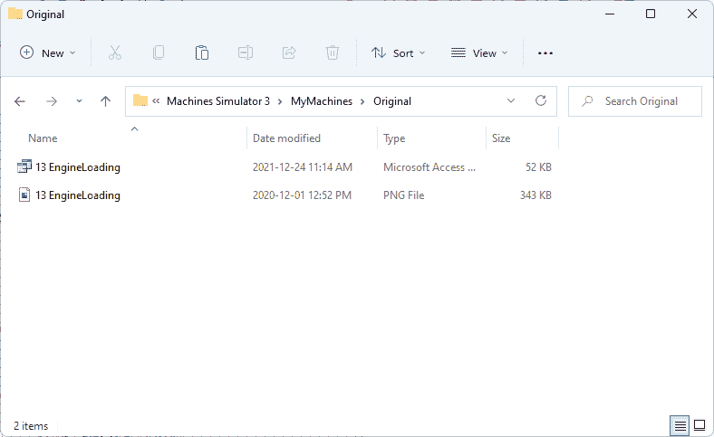 Paste the two files into another folder. In my case, I have used a folder called “Original” in “MyMachines.”
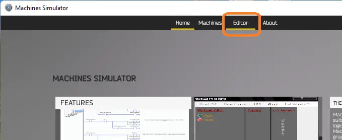 In the machine simulator, select “editor.”
 Select start for the Factory 1 Editor.
 Our factory environment will be displayed. Using the main menu, select Open under File.
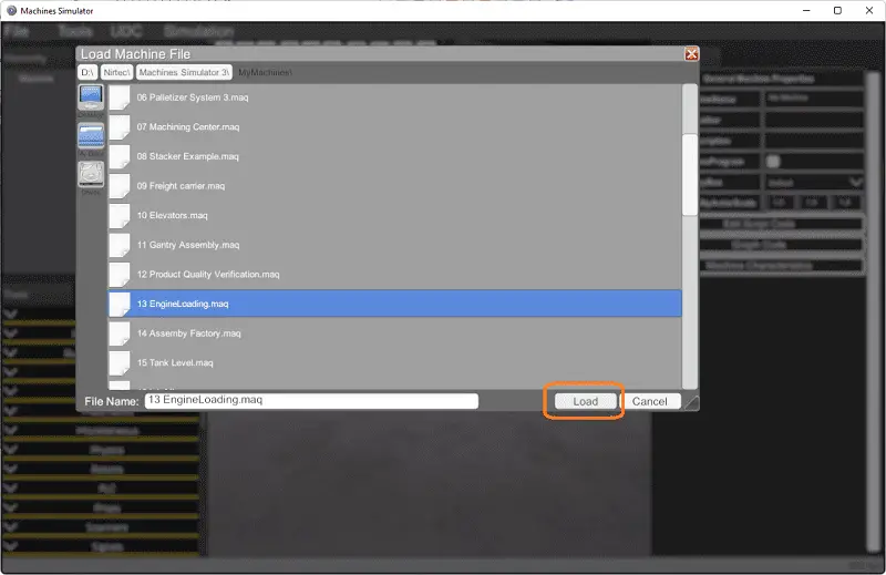 Select 13 EngineLoading.maq and then select the load button.
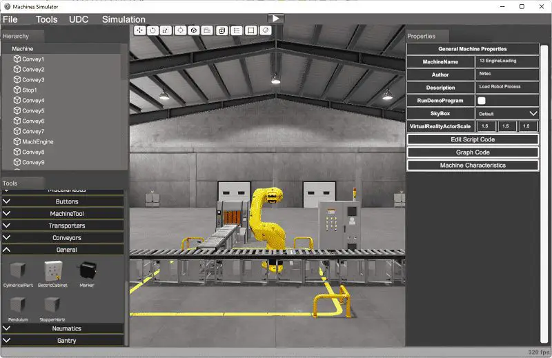 Our robotic cell machine can now be seen.
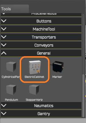 On the bottom left side, under tools, select the electrical cabinet under the general title.
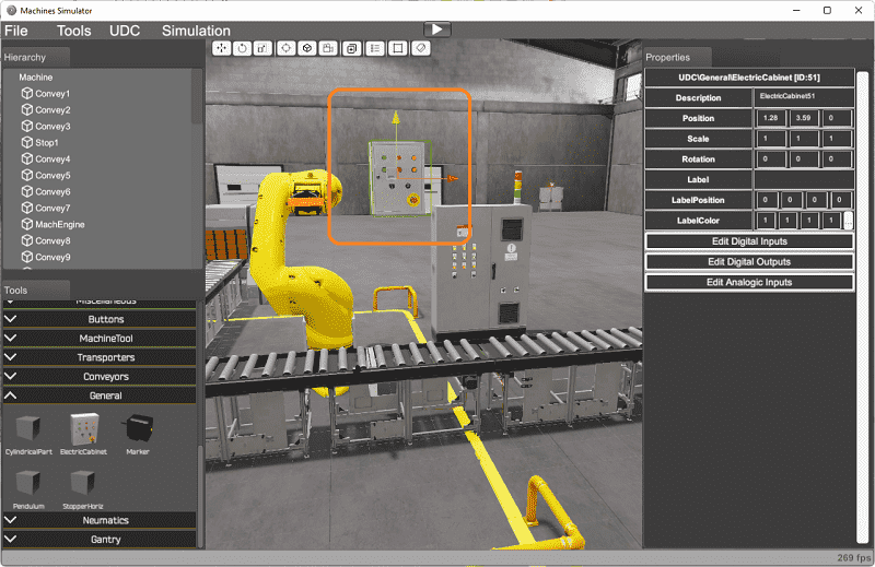 This will place the electrical cabinet into the robotic cell scene. The three arrows on the box can be used to move the cabinet to the location you want.
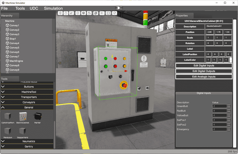 We will place this over the existing buttons on the larger cabinet. Position the panel to look like it is mounted to the current cabinet. Select the digital inputs from the properties tab on the right-hand side of the window.
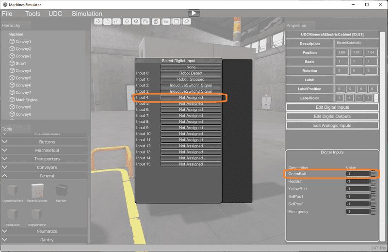 Select the three dots to the right-hand side of the green button text under digital inputs. This will prompt you to select the digital input. Select the not assigned input 4 buttons.
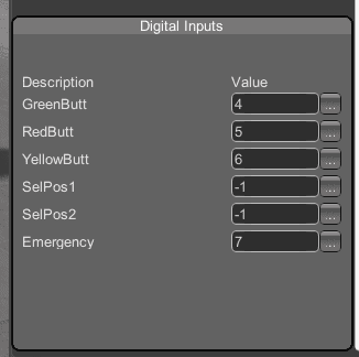 Continue to select the inputs for the red, green, and emergency stop buttons.
Note: Anything with a -1 indicates that this has not been assigned.
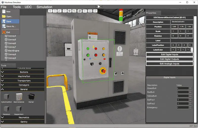 Here is the completed robotic cell scene. Select save under the main menu | File. This will save our modified machine under the name we opened.
Watch on YouTube: EasyPLC Factory Editor Robotic Cell Additions
Define the Inputs and Outputs: (Step 2 – Easyplc Robotic Cell)
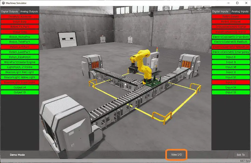
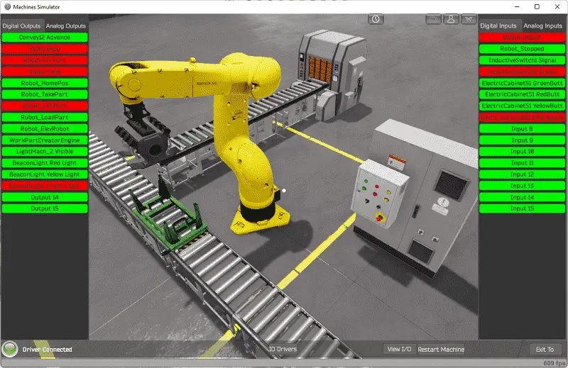
At the bottom of the machine simulator window, the View IO will display the inputs and outputs required for this warehouse stacker example. While still in demo mode, you can see the operation of the inputs and outputs.
 Use the following PLC signals to move the robot:
PLC Digital Outputs:
2 – Activate the robot fix system (to take the engine block)
4 – Move the robot to the home position
5 – Moves robot to the take engine position
6 – Move the robot to the lift engine position
7 – Move the robot to the load engine position (in pallet)
8 – Move the robot to the lift position (once the engine is loaded into the pallet)
PLC Digital Inputs:
0 – Active when the robot detects an engine in the gripping device
1 – Active when the robot finishes the movement
Use the following PLC signals to manage the machine:
PLC Digital Outputs:
0 – Start conveyor system
1 – Activate conveyor stop 1 (engine part)
3 – Activate conveyor stop 2 (pallet part)
9 – Request a new engine part
10 – Request a new pallet part
11 – Beacon Red Light
12 – Beacon Yellow Light
13 – Beacon Green Light
PLC Digital Inputs:
2 – Inductive SW1 signal for engine part
3 – Inductive SW2 signal for pallet part
4 – Electrical Cabinet Start
5 – Electrical Cabinet Stop
6 – Electrical Cabinet Jog
7 – Electrical Cabinet Reset (Emergency Stop)
The EasyPLC robotic cell engine loader example will require 14 digital outputs and 8 digital inputs.
If you are unsure what output or input is doing, start the engine loading machine in Start mode.
 Select the View IO on the bottom middle of the machine simulator window. You can manually run the robotic cell without any control or PLC connected.
 Clicking on the outputs will allow you to turn them on manually. You can then monitor the inputs to see their operation. The restart button on the bottom of the machine simulator window will reset the scene back to the start.
The following table will define the inputs and outputs (IO) and Modbus addresses in the BRX Do-More PLC that we will use for this program.
| Digital Type | Description | BRX Do-More PLC Modbus Address | Machine Simulator Modbus Address |
| PLC Output – MS Input | Conveyor 1 2 Advance | MI1 – 10001 | 0 |
| PLC Output – MS Input | Stop 1 Stop | MI2 – 10002 | 1 |
| PLC Output – MS Input | Robot Fix Part | MI3 – 10003 | 2 |
| PLC Output – MS Input | Stop 2 Stop | MI4 – 10004 | 3 |
| PLC Output – MS Input | Robot Home | MI5 – 10005 | 4 |
| PLC Output – MS Input | Robot Take Part | MI6 – 10006 | 5 |
| PLC Output – MS Input | Robot Lift Part | MI7 – 10007 | 6 |
| PLC Output – MS Input | Robot Load Part | MI8 – 10008 | 7 |
| PLC Output – MS Input | Robot Elevate Robot | MI9 – 10009 | 8 |
| PLC Output – MS Input | Work Part Create Engine | MI10 – 10010 | 9 |
| PLC Output – MS Input | Light Machine Create Pallet | MI11 – 10011 | 10 |
| PLC Output – MS Input | Beacon Light Red | MI12 – 10012 | 11 |
| PLC Output – MS Input | Beacon Light Yellow | MI13 – 10013 | 12 |
| PLC Output – MS Input | Beacon Light Green | MI14 – 10014 | 13 |
| PLC Input – MS Output | Robot Detect | MC1 – 1 | 0 |
| PLC Input – MS Output | Robot Stopped Movement | MC2 – 2 | 1 |
| PLC Input – MS Output | Inductive Switch 1 | MC3 – 3 | 2 |
| PLC Input – MS Output | Inductive Switch 2 | MC4 – 4 | 3 |
| PLC Input – MS Output | MS Start | MC5 – 5 | 4 |
| PLC Input – MS Output | MS Stop | MC6 – 6 | 5 |
| PLC Input – MS Output | MS Jog | MC7 – 7 | 6 |
| PLC Input – MS Output | MS Reset Sequence | MC8 – 8 | 7 |
Note: The machine simulator will be offset by one on the Modbus Addresses. See the video below for the demo mode and determining inputs and outputs.
Develop a logical sequence of operation: (Step 3 – Easyplc Robotic Cell)
A flow chart or sequence table is used to understand the process that must be controlled thoroughly. It must also answer questions like the following:
What happens when electrical power and/or pneumatic air is lost? What happens when the input/output devices fail? Do we need redundancy?
This step is where you will spend most of your time. Understanding everything about the operation will save you time. It will help prevent you from continuously re-writing the PLC program logic. Knowing all these answers upfront is vital in developing the PLC program.
The sequence of operation comes down to using indirect addressing (Pointers) in the PLC.
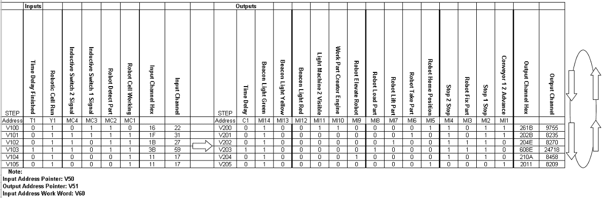 Here is the sequence table for the robotic cell. If the input conditions are met, then the outputs are set. The following input conditions are looked at. If they are equal, then the subsequent outputs are selected. This will continually cycle through the table.
A PLC programmer must know how everything about the sequence and operation of the machine before programming.
Ask questions or view existing documentation to ensure that you know the logical steps to the machine operation.
Develop the BRX Do-More PLC program: (Step 4 – Easyplc Robotic Cell)
Writing the ladder logic code for the PLC example will be the next step in our program development. We will be using the Do-More Designer programming software with the BRX Do-More PLC.
The BRX Do-More Series will install the program, communicate the controller instructions, and address the controller.
 Select the system configuration using the configure icon on the main menu. You can also call this up by selecting it under tools in the project browser window. The third way to get to the system configuration is by using the main menu | PLC | System configuration…
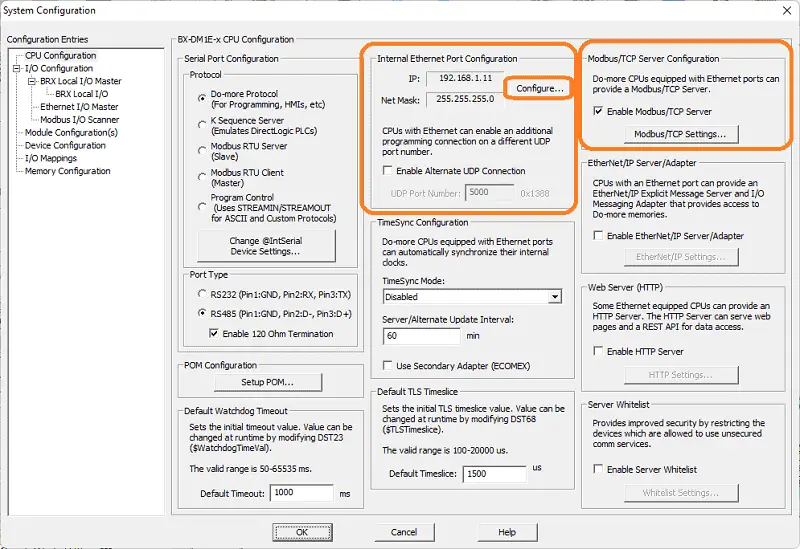
Select the configure button under the internal Ethernet port configuration.
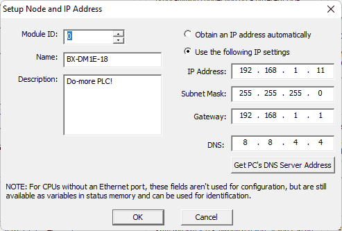 We will use a static IP address for the Ethernet port. Here are our settings for the port. Ensure that the Enable Modbus / TCP Server is selected. Click the Modbus / TCP Settings… button. Select OK to return to the system configuration window.
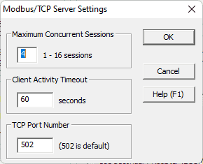 We will leave the default port of 502 for our Modbus communication.
Our PLC is now set up as a Modbus TCP Server to the EasyPLC Modbus TCP Client. Make a note of the static IP address we are using for the BRX Do-More PLC. This will be used later to connect to the EasyPLC machine simulator.
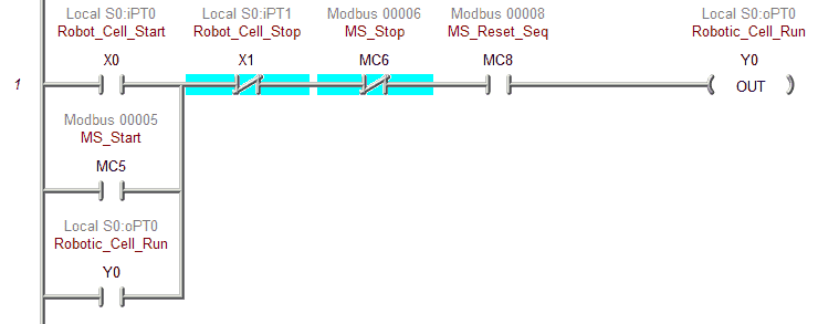 The first rung of ladder logic will control the robotic cell run output. This can be controlled using the physical IO on the BRX PLC or the buttons added to the machine simulator above.
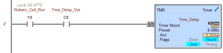 The time delay output can be controlled when the robotic cell is running. This is part of the sequence table discussed above.
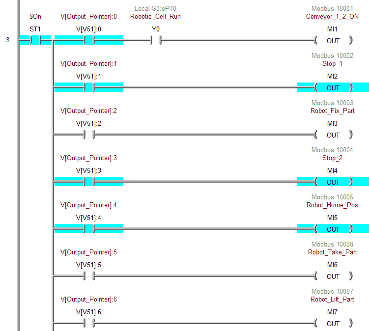
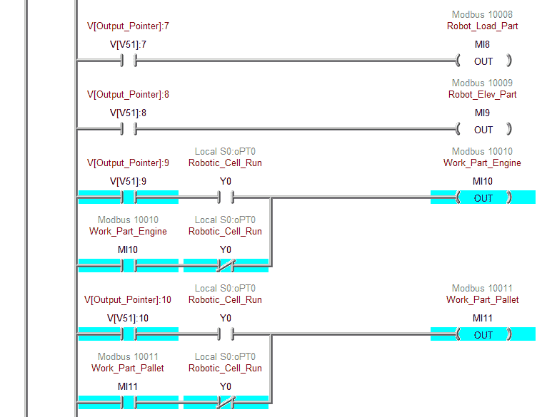
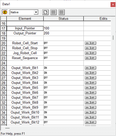
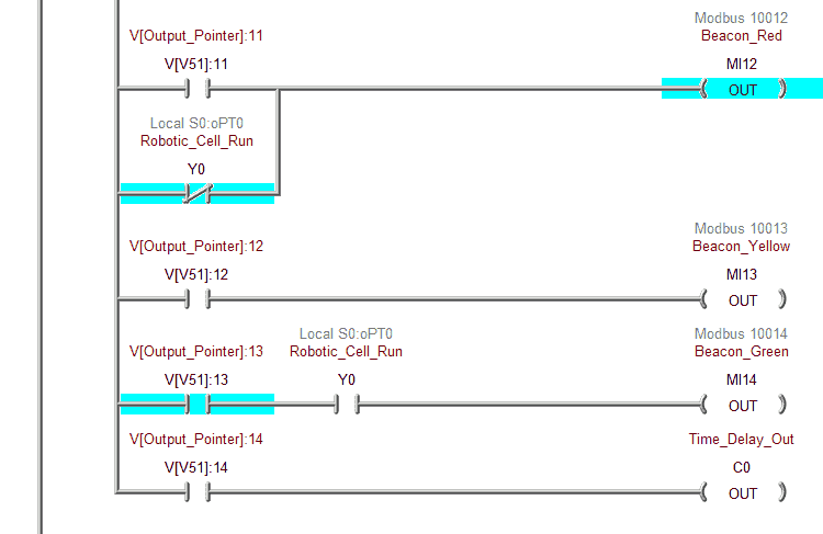 Individual bits are addressed from the sequence table. This uses indirect addressing (pointers) to select what bits will be on or off. V51 is used as the output pointer. This pointer will have the values from 200 to 206 to represent V200 to V206 from the sequence table above.
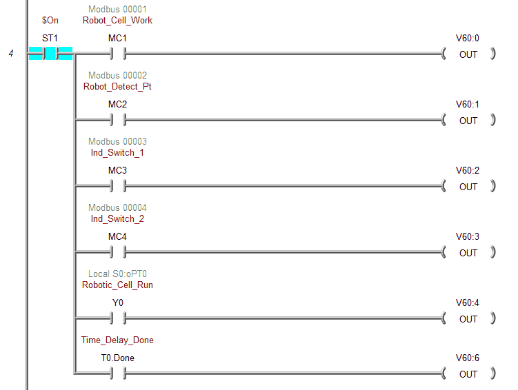 The inputs are used to store individual bits in V60. This will be our comparison word for the input table.
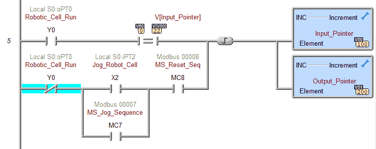 The input word is compared to the input pointer (V50) when the robotic cell is running. This pointer will contain values from 100 to 106. (V100 to V106)
If the inputs match, the input and output pointers are incremented by 1.
If the robotic cell is not running, then the jog buttons can be used to increment the pointers.
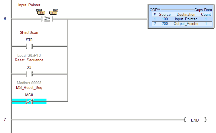 The input pointer is compared to the last input in the table. If it is equal to or greater than the value 106, the pointers are reset. They can also be reset by the first scan of the PLC or the reset inputs.
Call up the memory image manager by selecting it from the main menu | Tools.
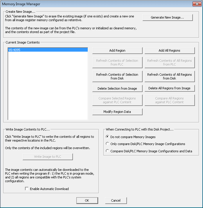 Use the add region button to select the V0-4095 memory area. Select this region and then select the modify region data button.
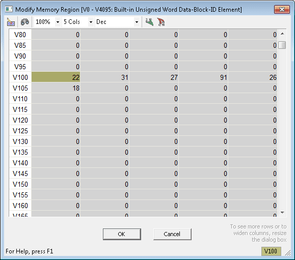 Scroll down to the input address location V100 and fill in the input table.
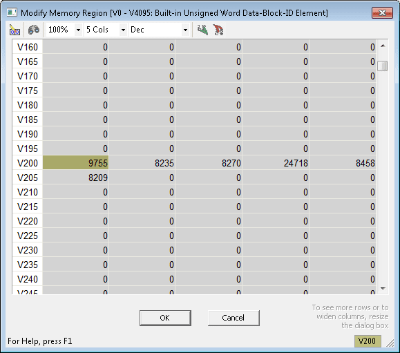 We can also fill in the output locations starting at V200. Select OK.
 When connected to the BRX Do-More PLC, selecting the written image to PLC will transfer this area to the PLC. You can also enable automatic downloads, which will be transferred when writing the program to the PLC in program mode.
Watch the video below to see this PLC program in action
Test the program: (Step 5 – Easyplc Robotic Cell)
We will be using Modbus TCP on our BRX Do-More PLC to communicate to the EasyPLC Machine Simulator.
Call up the engine loading machine simulator in start mode.
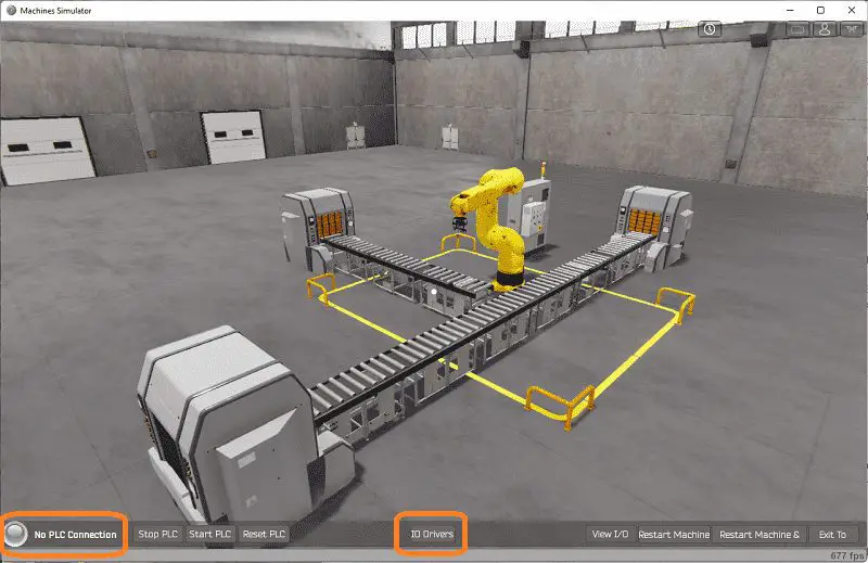 The status of the machine simulator will be along the bottom of the screen. Currently, we have no PLC connected. Select IO Drivers on the bottom middle of the screen.
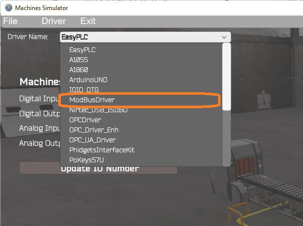 The EasyPLC driver is selected by default. Under the driver pull-down menu, select “ModBusDriver.” This driver will communicate Modbus TCP (Ethernet) and Modbus RTU (Serial). Select the down arrow on the driver’s name.
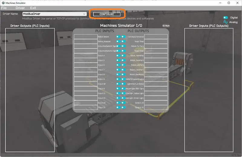 Select the configure button.
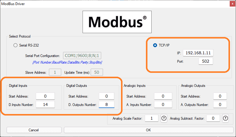 We can now enter the information for our Modbus driver. Select TCP/IP. This means the Ethernet port on the computer will communicate to the PLC.
The digital inputs from MS to the BRX PLC will be 100001 to 100015. This will start at address 0 due to the offset of 1. Digital outputs from MS to the Productivity PLC will be 1 to 9. This will begin at address 0 due to the offset of 1. Select the OK button.
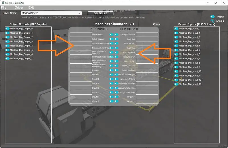 You will now see the inputs and outputs specified for the Modbus driver. We can now manually assign the driver outputs to the PLC inputs and the driver inputs to the PLC outputs. However, the automatic assignment works well and will save you time.
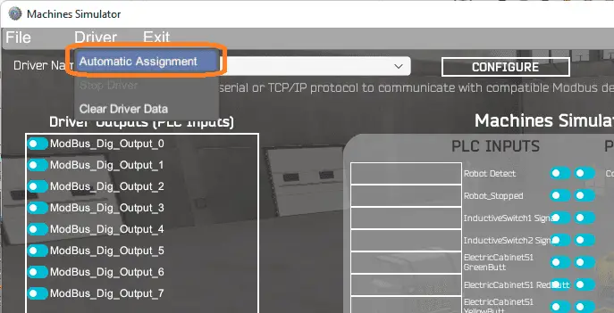 Select Automatic Assignment from the driver option in the main menu.
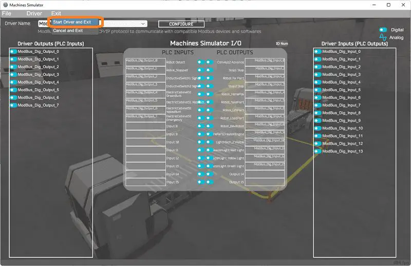 This will automatically assign the PLC IO to the Machine Simulator IO. Select start driver and exit from the main menu.
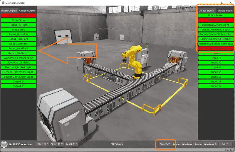
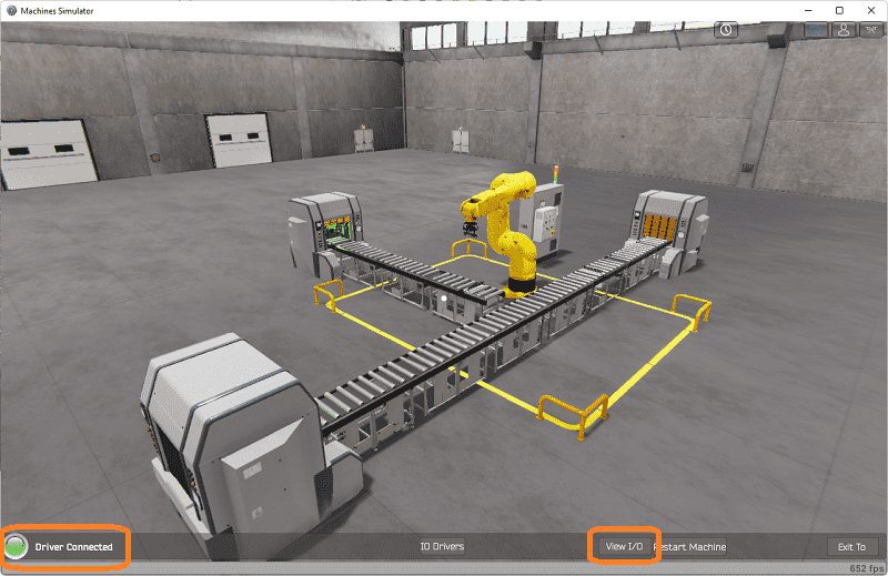 On the bottom left side of the window, you will see that the driver is communicating to the PLC by the green light. Select view IO to know the input and output status of the machine simulator.
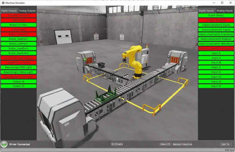 Ensure that the PLC is in run mode. We can see the operation of our robotic cell. Select the start from the machine simulator electrical panel we added above.
 The digital inputs and outputs of the MS will correspond to the PLC controller.
Using Machine Simulator (MS) to test the program will ensure that our program works.
 Using the Data View window of the Do-More Designer programming software, we can also watch the inputs and output operations.
 Watch the video below to see this on the operation.
Download the BRX Do-More PLC sample program, EasyPLC Machine Simulator Modifications, and sequence table here.
Watch the video below to see the five steps of program development applied to the engine loading robotic cell. The machine simulator is one of the best applications to help you learn PLC programming.
EasyPLC Software Suite is a complete PLC, HMI, and Machine Simulator Software package. This PLC learning package includes the following:
Easy PLC – PLC Simulation allows programming in Ladder, Grafcet, Logic Blocks, or Script.
HMI System – Easily create a visual human-machine interface (HMI)
Machine Simulator – A virtual 3D world with real-time graphics and physical properties. PLC programs can be tested using the EasyPLC or through other interfaces. (Modbus RTU, TCP, etc.)
Machine Simulator Lite – Designed to run on Android Devices.
Machine Simulator VR – Virtual Reality comes to life so you can test, train or practice your PLC programming.
Purchase your copy of this learning package for less than USD 75 for a single computer install or less than USD 100 to allow different computers.
Receive 10% off the price by typing in ACC in the comment section when you order. http://www.nirtec.com/index.php/purchase-price/
Learn PLC programming the easy way. Invest in yourself today.
Watch on YouTube: EasyPLC Simulator Robotic Cell BRX Do-More PLC
If you have any questions or need further information, please contact me.
Thank you,
Garry
If you’re like most of my readers, you’re committed to learning about technology. Numbering systems used in PLCs are not challenging to learn and understand. We will walk through the numbering systems used in PLCs. This includes Bits, Decimal, Hexadecimal, ASCII, and Floating Point.
To get this free article, subscribe to my free email newsletter.
Use the information to inform other people how numbering systems work. Sign up now.

The ‘Robust Data Logging for Free’ eBook is also available for free download. The link is included when you subscribe to ACC Automation.