Here are the top 7 problems and concepts beginners struggle with using ladder logic (Ladder Diagram). Ladder logic is a programming language used in PLCs, and it is based on the graphical representation of electrical relay logic circuits. Many beginners struggle with ladder logic because it requires a different mindset than traditional programming languages like C++, Python, or Java.
We will look at the seven common issues beginners face due to a lack of understanding of ladder logic. Stick around until the end to see the bonus problem that is not well understood. Let’s get started.
#1 – Thinking procedurally instead of in parallel
In ladder logic, the ladder rungs are executed in parallel, meaning all the rungs are evaluated simultaneously in each scan cycle of the PLC.
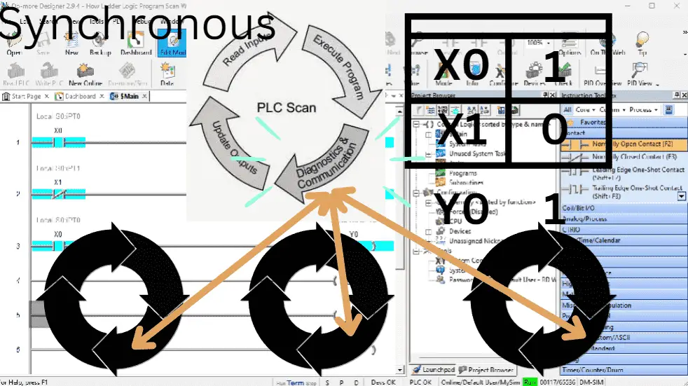
Beginners accustomed to sequential programming may find it challenging to break away from the procedural mindset and design their logic in parallel. Ladder logic is solved from left to right, top to bottom. The output from the previous rung is available for the next rung to use.
#2 – Misinterpreting contacts and coils in ladder logic
Contacts in ladder logic represent the status of input signals, while coils represent the status of output signals. Beginners may confuse these elements, leading to incorrect logic design and output behavior. Ladder diagrams are dirived from electrical drawings. Understanding the difference between normally open (NO) and normally closed (NC) contacts is essential for writing accurate PLC programs. In ladder logic, always refer to the input and determine its state.
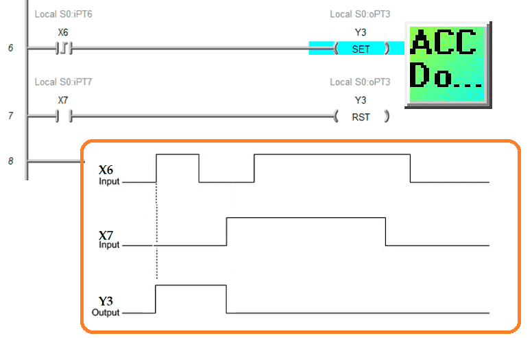
#3 – Difficulty (problems) with timers and counters
Timers and counters are fundamental components in PLC programming. Beginners might struggle to grasp the concept of timers (delay on or off) and counters (up or down). Incorrectly configuring timers and counters can result in unexpected behavior in the system. When looking at timers and counters, always refer to a timing diagram. This will show you the essential operation of these instructions.
#4 – Overlooking scan cycle considerations
PLCs execute their programs in scan cycles, where the entire ladder program is scanned repeatedly (cyclically). Beginners may not fully understand the implications of this cyclic nature, leading to logic conflicts, race conditions, or undesired outputs.
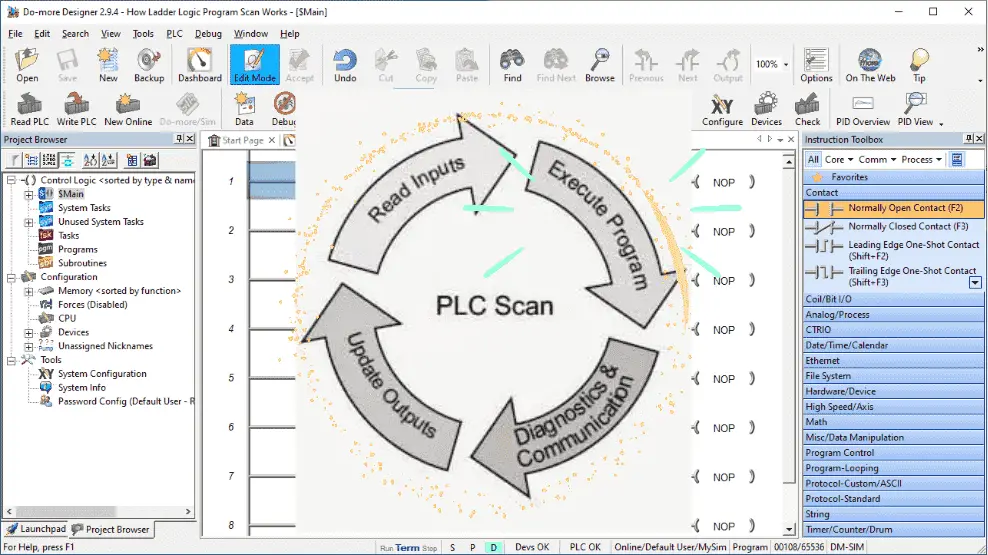
There are four essential parts to a PLC scan cycle. Read inputs, execute logic (program), diagnostics and communication, and update outputs. Since outputs are generally set only once per scan, the last ladder logic scanned will be the one that sets an output if the logic is duplicated.
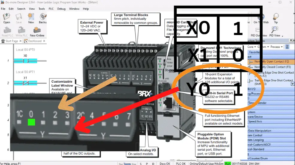
#5 – Lack of knowledge about memory types
PLCs have different types of memory, such as input, output, and internal memory, for storing variables and data. Beginners might not be aware of these memory types and their proper usage, leading to data corruption or unintended results. An example of this would be retentive memory. If power is removed from the PLC and it comes back on, do you need to remember the conditions before the power removal?
All memory is just bits in the PLC. PLC memory is bits, just like a computer. They can be set to a 1 or 0. Putting these bits together will allow for a word. The interpretation of these words will determine the value. (BCD, HEX, Float, etc.) PLCs can convert from one to another.
#6 – Not leveraging advanced instructions
Ladder logic supports advanced instructions, such as math operations, data manipulation, and comparison functions. Every PLC manufacturer will have the basics and different dedicated instructions within their controller. Beginners may not explore or fully utilize these powerful instructions, resulting in less efficient and more complex programs. An example is the DRUM instruction on the Automation Direct PLC offerings.
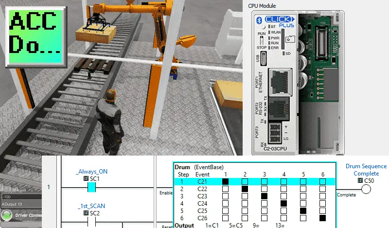
Click PLC Drum Instruction Sequencer
BRX Do-More Drum Sequencer
P1000 Drum Instruction
P2000 Drum Instruction
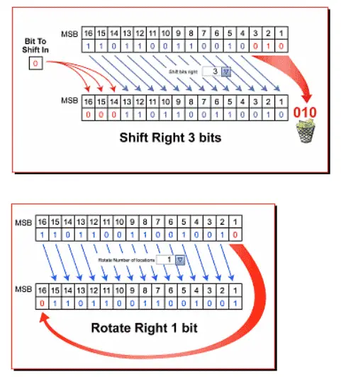
What other advanced instructions do you use? Shift registers, rotate, or masking? Let me know in the comments below.
#7 – Difficulty in troubleshooting
Due to the graphical nature of ladder logic, beginners might find it challenging to debug their programs effectively. Identifying and resolving logic errors or programming mistakes can be more demanding compared to textual programming languages due to the scan. PLCs may have built-in troubleshooting within their dedicated programming software to assist you.

Productivity 2000 Debug Mode
Productivity 1000 Debug Mode
Do-More Designer (BRX) Debug Mode
Bonus – Developing a PLC Program
A common beginner question is how to start programming the PLC. Developing a programmable logic controller (PLC), program can be broken down into five steps. These programming steps are as follows:
Five Steps to PLC Program Development
Step 1 – Define the task
Step 2 – Define the Inputs and Outputs
Step 3 – Develop a logical sequence of operation
Step 4 – Develop the PLC program
Step 5 – Test the program
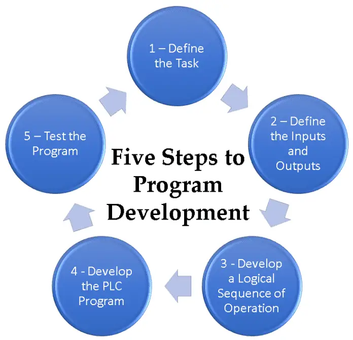
These five steps to PLC program development will help you understand, program, and troubleshoot your automated machine.
The actual PLC programming is the second last step. Beginners make the mistake of not fully understanding the logic of the system to be accomplished. This then makes the actual programming of the system longer with constant rewrites and updates based on new knowledge.
A PLC programmer should know everything about the system before programming.
Additional examples of PLC program development using the five steps.
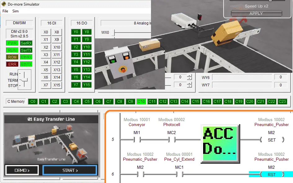
Click PLC – Easy Transfer Line Programming – Video
Productivity PLC Simulator – Chain Conveyor MS – Video
Five Steps to PLC Program Development – Die Stamping
PLC Programming Example – Process Mixer
PLC Programming Example – Shift Register (Conveyor Reject)
PLC Programming Example – Paint Spraying
PLC Programming Example – Delay Starting of 7 Motors
PLC Programming Example – Pick and Place
PLC Programming Example – Sorting Station (Shift Register)
PLC Programming Example – Palletizer
To overcome these challenges of ladder diagrams, beginners should thoroughly understand the basic concepts of ladder logic. They can practice designing small programs, testing them in a simulation environment, and observing the PLC’s behavior. Refer to the PLC manufacturer’s documentation on the hardware and software you use. These top items of knowledge will be beneficial in improving ladder logic proficiency.
PLC Beginner’s Guide to PLC Programming
There are many different PLC manufacturers with other hardware and software. All of the programmable logic controllers have similar basic features. Here is how I would approach learning about basic PLCs.
Once you are familiar with the basics of the PLC, you will then learn specifics for the controller you will be programming.
This is the easiest way to learn about PLC programming.
Watch on YouTube: Top 7 Problems with Beginners Using Ladder Logic
If you have any questions or need further information, please contact me.
Thank you,
Garry
If you’re like most of my readers, you’re committed to learning about technology. Numbering systems used in PLCs are not challenging to learn and understand. We will walk through the numbering systems used in PLCs. This includes Bits, Decimals, Hexadecimal, ASCII, and Floating Points.
To get this free article, subscribe to my free email newsletter.
Use the information to inform other people how numbering systems work. Sign up now.

The ‘Robust Data Logging for Free’ eBook is also available as a free download. The link is included when you subscribe to ACC Automation.