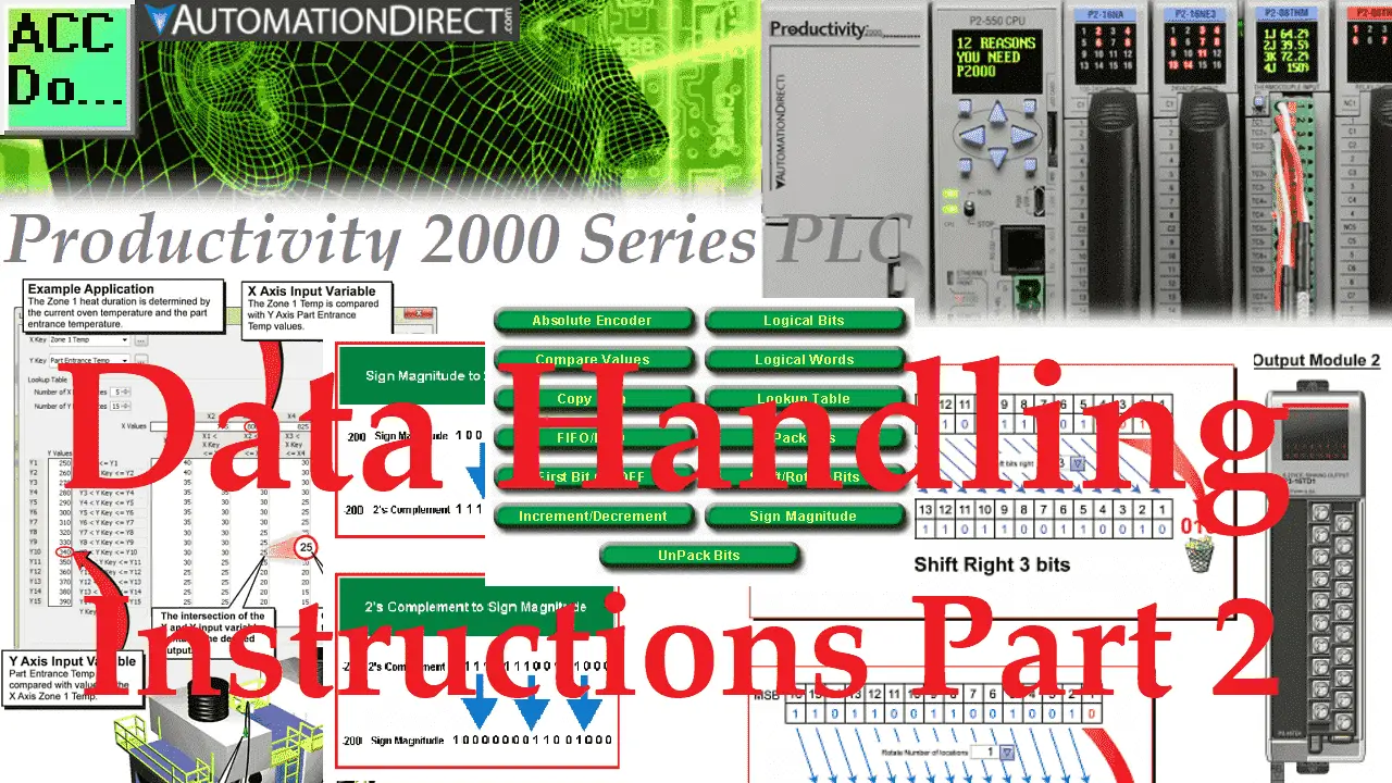
Data handling instructions are used to perform movement and manipulations of the memory in the programmable logic controller. The Productivity 2000 Series PLC has fifteen different data handling instructions that can be used in various applications. This includes all of the data handling instructions. Understanding the full capability of the PLC that you are programming is essential.
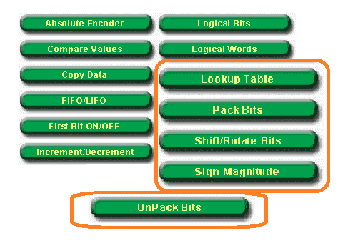
In this second part, we will be looking at the following instructions:
Lookup Table (LKUP) – Find a value within an XY Table by looking at the intercept of a referenced X Axis value and Y-Axis value.
Pack Bits (PKB) – Convert up to 32 Boolean Tag Bits or Constant Bits into an Output Integer Tag.
Pack Word (PKW) – Convert up to four-bit tags, two 16-bit tags, or four Constants into a 16 or 32-bit Destination Tag.
Shift / Rotate Bits (SFR) – Shift or Rotate Bits of a Tag or Constant value.
Sign Magnitude (SMAG) – Convert Sign Plus Magnitude data type values to 2’s Complement or Convert 2’s Complement data type values to Sign Plus Magnitude.
UnPack Bits (UPKB) – Convert up to a 32 Bit Integer Tag or Constant into Boolean Tags.
UnPack Word (UPKW) – Convert one 32-bit or 16-bit source tag into four 8-bit tags or two 16-bit tags.
A review of data handling instructions part 1 can be found here. Here is a link to the video. Let’s start with the Productivity 2000 Series PLC data handling instructions part 2.
Previously in this Productivity 2000 series PLC, we have discussed the following:
P2000 Hardware Features – Video
Productivity Suite Software Install – Video
Communication (System Configuration) – Video
First Program – Video
Debug Mode – Video
PLC Program Documentation – Video
PLC CPU Display – Video
PLC Online Programming – Video
PLC Tag Database – Video
Ladder Logic Contacts – Video
Ladder Logic Outputs – Video
Timers – Video
Counter – Video
Productivity 2000 PLC Ladder Logic Math – Video
Data Handling Instructions Part 1 – Video
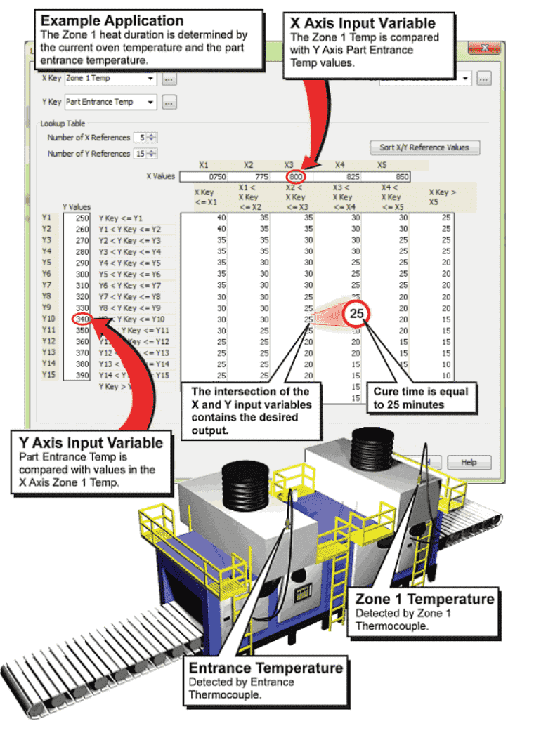
Lookup Table (LKUP) – Productivity Data Handling
This instruction will find a value within an XY Table. It will look at the intercept of a referenced X Axis value and Y-Axis value.
We will use a structure named Lookup_Table. This will set up our inputs XKey, YKey, and Output.
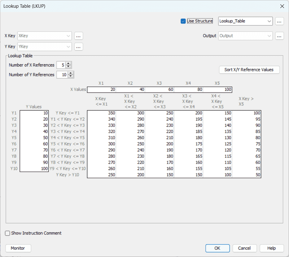
We now enter the data in the table. This will give us the grid shown above. Then the number of X references will be 5, and the number of Y references will be 10.
We can now define the tags for Lookup_Table. Make XKey and YKey retentive with an initial value of 60 each.
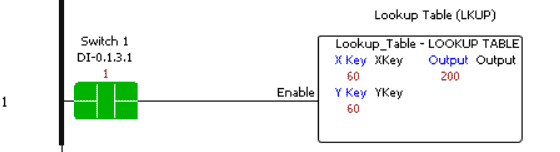
When Switch1 is on the data handling lookup table, the instruction will take the XKey and YKey inputs and send the corresponding value based on the table specified to the Output.
Pack Bits (PKB) – Productivity Data Handling
This instruction will convert a maximum of 32 Boolean Tag Bits or Constant Bits into an Output Integer Tag. In this example, we can pack the 16 bits of an input card into an output number.
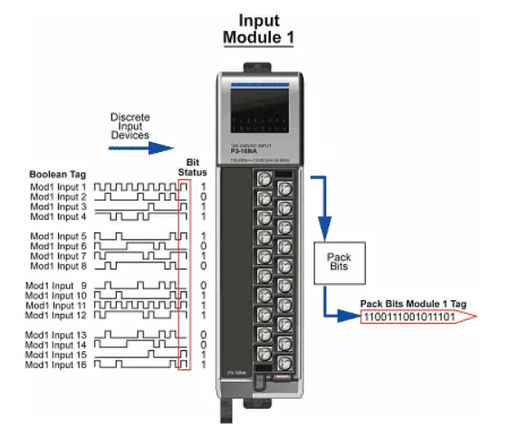
We will specify the tag Pack_Bits_Out. We will send the value to the Pack_Bits_Out tag using the eight switches on our input card.
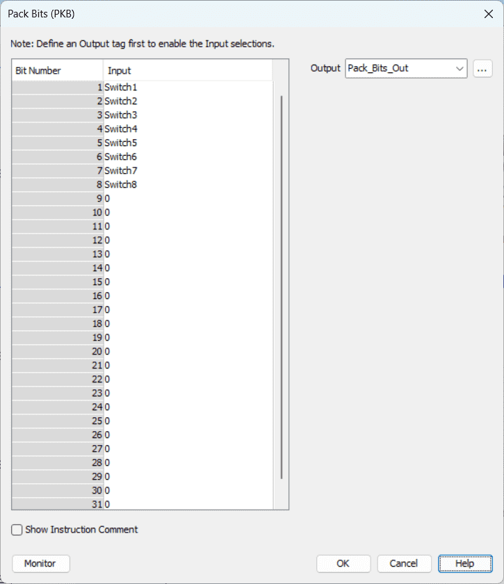
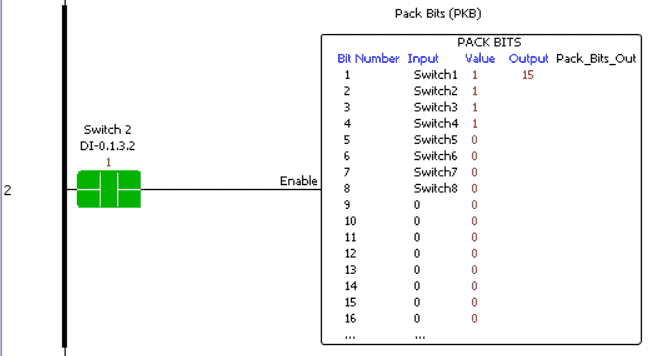
When Switch2 is on, the first eight switches will be converted into the Pack_Bits_Out flag on our data handling instruction.
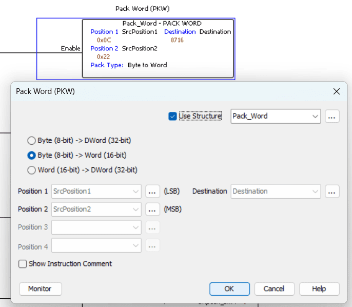
Pack Word (PKW) – Productivity Data Handling
This instruction will convert up to four 8-bit tags, two 16-bit tags, or four Constants into a 16 or 32-bit Destination Tag. This example will combine two bytes of data from two words into the destination value.
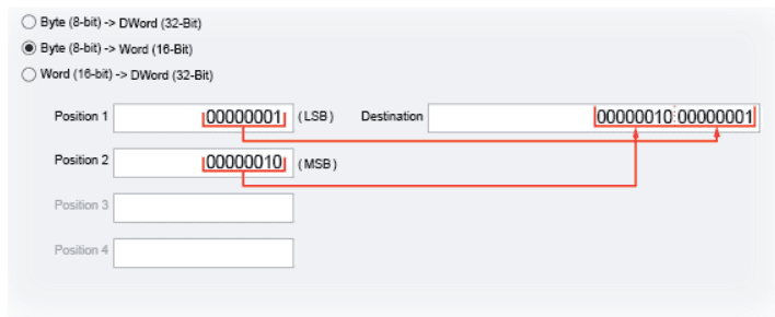
We will use the structure name Pack_Word and specify Byte (8-bit) to Word (16-bit)
We will set Positions 1 and 2 as retentive with the initial values of 12 and 34, respectively.
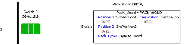
When Switch3 turns on, the first 8 bits of Position 1 will be the least significant Byte. The first 8 bits of Position 2 will be the most significant Byte of the Output.
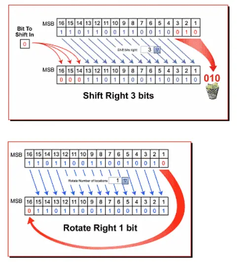
Shift / Rotate Bits (SFR) – Productivity Data Handling
This instruction will Shift or Rotate Bits of a Tag or Constant value. In the examples, a shift will delete the bits that are shifted out, and the rotate will move the end bit to the beginning bit.
We will call the structure Shift_Rotate. Select Rotate Left, Include Sign Bit and One-Shot.
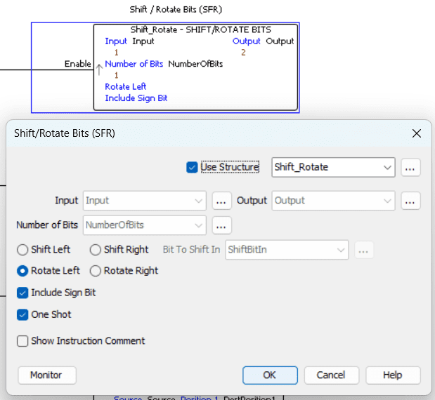
Set the Input and Number to Shift/Rotate to retentive with the initial value of 1 each.
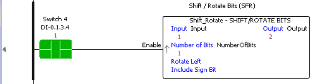
When Switch4 transitions from off to on, the Output will shift by one left. When the lost bit of the Output is shifted, it will rotate back to the first bit. This is a robust data handling instruction on our Productivity Suite unit.
We have covered Shift Registers in previous posts. Here is a couple that will show you what can be done with rotating and shifting instructions.
EasyPLC Paint Line Bit Shift – Video
PLC Programming Example Sorting Station – Video – Testing Video
PLC Programming Example – Shift Register (Conveyor Reject) – Video
Sign Magnitude (SMAG) – Productivity Data Handling
This instruction will convert Sign Plus Magnitude data type values to 2’s Complement or Convert 2’s Complement data type values to Sign Plus Magnitude.
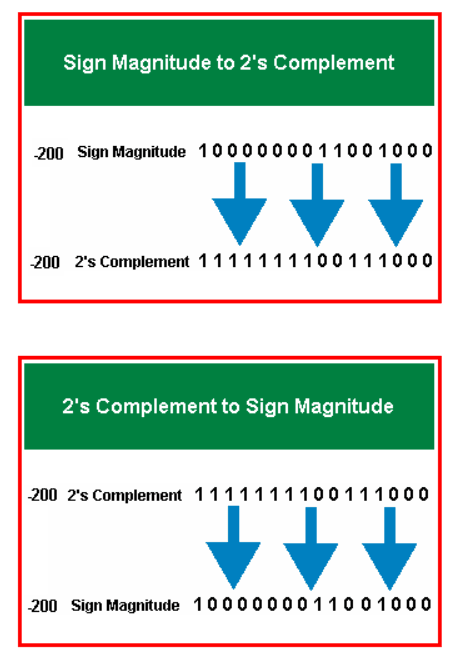
The following link is a good tutorial on signed binary numbering systems.
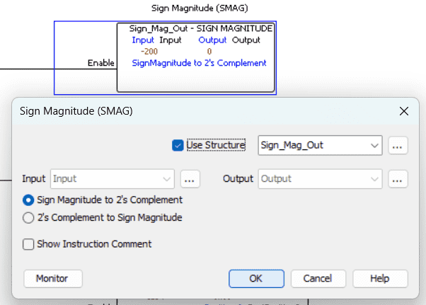
We will use the structure name Sign_Mag_Out and select Sign magnitude to 2’s Complement.
Make the Input memory retentive with an initial value of -200.
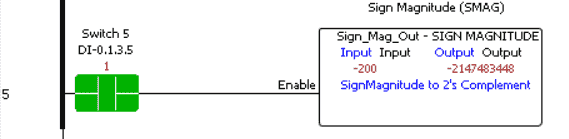
When Switch5 is turned on, the Output will contain the sign-magnitude to 2’s Complement of the Input number.
UnPack Bits (UPKB) – Productivity Data Handling
This instruction will convert up to a 32 Bit Integer Tag or Constant into Boolean Tags. In this example, we are setting all 16 bits of an output card.
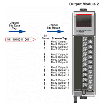
We will use the Pack_Bits_Out as the input to this instruction.
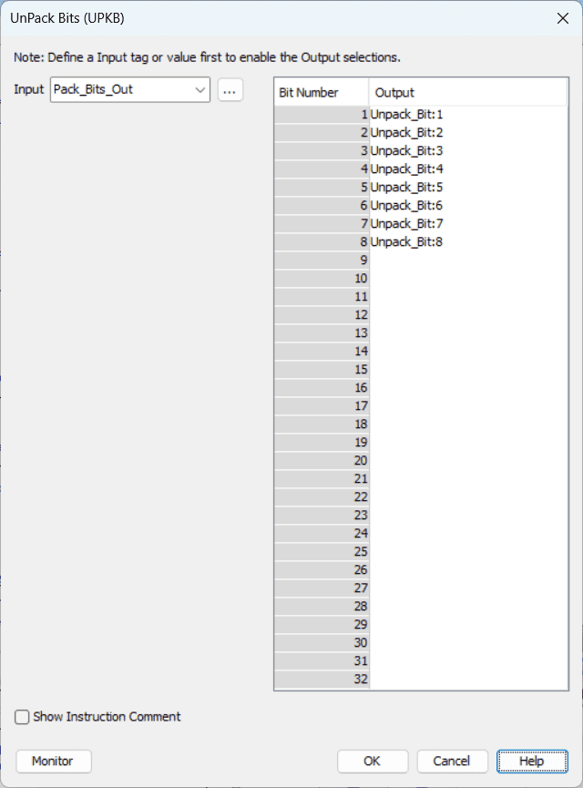
This represents the eight switches that we packed into the Output. This instruction will do just the opposite. Our Output will be Unpack_Bit:1 to 8.
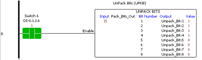
When Switch6 is turned on, the input number will be broken into bits. In our case, this represents the switches when we packed the input.
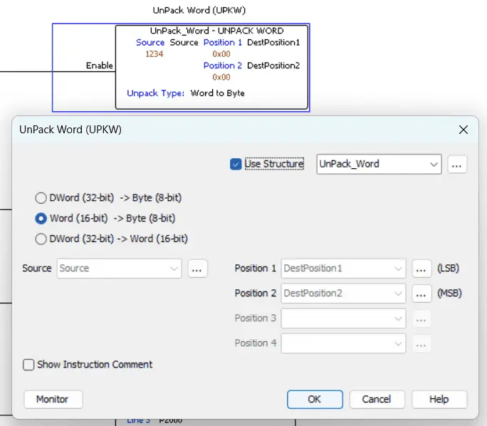
UnPack Word (UPKW) – Productivity Data Handling
This instruction will convert one 32-bit or 16-bit source tag into four 8-bit tags or two 16-bit tags. In this example, we take a 16-bit word and convert it into two 8-bit bytes.
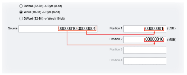
We will name the structure UnPack_Word. Select “Word (16-bit) to Byte (8-bit) “.
Our input (Source) will be broken into two 8-bit bytes of data.
Make the source memory retentive and set its initial value to 1234.
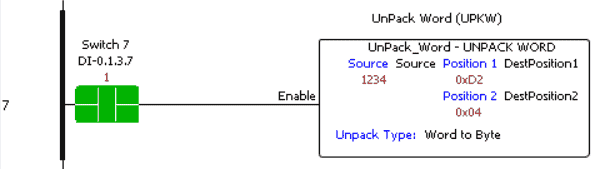
Switch7, when turned on, will unpack the source into two bytes. This happens every scan as long as Switch7 is on. (The rung is true.)
Download the PLC program here.
Watch the video below for the data handling instructions used in our Productivity 2000 Series PLC.
Productivity 2000 Series PLC from Automation Direct
Overview Link (Additional Information on the Unit)
Configuration (Configure and purchase a system – BOM)
User Manual and Inserts (Installation and Setup Guides)
Productivity Suite Overview (Features of the fully functional free software package for the Productivity Family of PLC (PAC) controllers)
Productivity Suite Programming Software (Free Download Link)
This software contains all the instructions and helps files for the Productivity Series.
Watch on YouTube: Productivity 2000 PLC Data Handling Part 2
If you have any questions or need further information, please contact me.
Thank you,
Garry
If you’re like most of my readers, you’re committed to learning about technology. Numbering systems used in PLCs are not challenging to learn and understand. We will walk through the numbering systems used in PLCs. This includes Bits, decimals, Hexadecimal, ASCII, and Floating points.
To get this free article, subscribe to my free email newsletter.
Use the information to inform other people how numbering systems work. Sign up now.

The ‘Robust Data Logging for Free’ eBook is also available for free download. The link is included when you subscribe to ACC Automation.