The program control method and instructions will allow us to specify what parts of the logic get solved and when this happens. This will control how the PLC will scan and solve your logic in your program using a synchronous PLC Scan. Understanding the PLC program scan post will explain synchronous and asynchronous program scanning.
Task Management provides a method to see the overall flow of your PLC program. Individual ladder logic programs get solved left to right, top to bottom. The result of the rung before is available for the next rung. Looking into the folders of task management, we can see blocks of code. These blocks contain the ladder logic that will solve our logic. Instructions within the ladder logic code can also determine how the PLC will solve the logic.
We will be looking at using program control in the Productivity 2000 Series PLC.
Let’s get started.
Previously in this Productivity 2000 series PLC, we have discussed the following:
P2000 Hardware Features – Video
Productivity Suite Software Install – Video
Communication (System Configuration) – Video
First Program – Video
Debug Mode – Video
PLC Program Documentation – Video
PLC CPU Display – Video
PLC Online Programming – Video
PLC Tag Database – Video
Ladder Logic Contacts – Video
Ladder Logic Outputs – Video
Timers – Video
Counter – Video
Productivity 2000 PLC Ladder Logic Math – Video
Data Handling Instructions
Part 1 – Video
Part 2 – Video
Array Functions
Part 1 – Video
Part 2 – Video
Part 3 – Video
Task Management Panel – Productivity Program Control
The Task Management Panel allows you to add, edit, and delete Tasks (ladder programs) within a project file. It will enable you to split your program into smaller segments to organize and make it easier to understand.
The task management panel is displayed on the main screen. You can position it where you want it. It can also be called from the main menu | Tools | Task Management Panel.
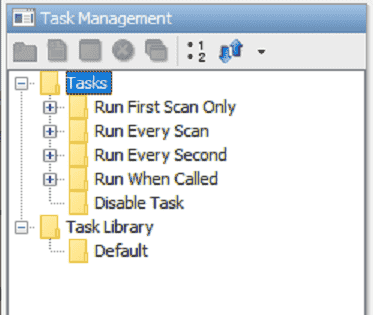
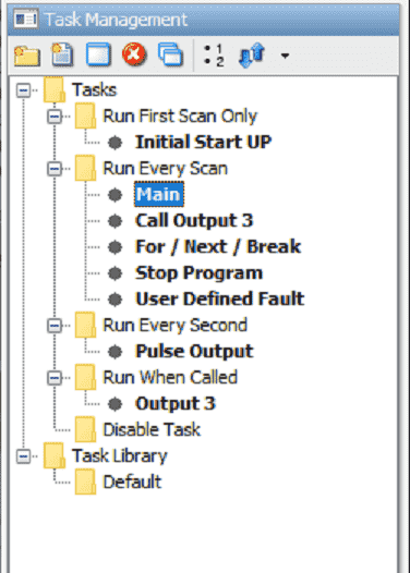
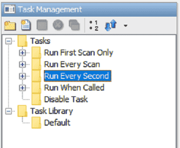
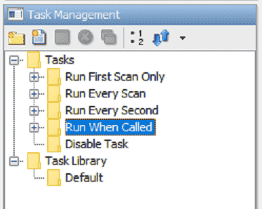
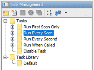
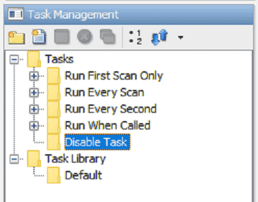
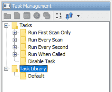
The task management panel provides five (5) folders to place your ladder program tasks.
Run First Scan Only: Tasks in this folder are executed only on the First Scan when going to Run. These Tasks execute in the order they appear in the folder, and they execute before Tasks in the Run Every Scan and Run Every Second folder.
Run Every Scan: Tasks in this folder are executed Every Scan during Run. These Tasks execute in the order they appear in the folder, and they execute before Tasks in the Run Every Second folder. This is where a majority of your programming logic will be seen.
Run Every Second: This folder is for lower-priority Tasks that do not need to execute Every Scan. Tasks in this folder are executed once per second during the Run. These Tasks execute in the order they appear in the folder, and they execute after Tasks in the Run Every Scan folder.
Run When Called: Tasks in this folder are executed only when Called using a Call Task instruction.
Disable Task: Tasks in this folder are not executed. Placing a Task here disables it. This is ideal for trying new logic when developing code.
Run First Scan Only – Productivity Program Control
These tasks can be used to reset or initialize your program upon a power interruption or before going to run mode.
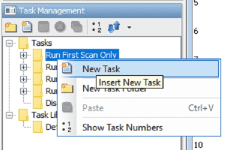
Select the top left icon under the Task Management window to add new tasks (Blocks of ladder code) to the task management folder.
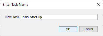
We can then name the new task. In our case, we will call this an “Initial Start Up.” Select OK.
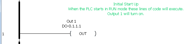
Our code can now be placed in this new task that we have created.
In our case, when the PLC starts in RUN mode, Output 1 will turn on. Since we do not have any other code in the program that will turn Output 1 off, it will remain on while the PLC is in run mode.
Run Every Second – Productivity Program Control
Tasks in this folder will be executed every second. To demonstrate this, we will pulse an output on and off every second.
Start a new task under the Run every second folder. We will call this Pulse Output.
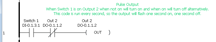
When switch 1 is on, Output 2, when not on, will turn on, and when on, it will turn off alternatively. Since this code is run every second, the output will flash one second on and then one second off.
Run When Called – Productivity Program Control
(Call Task / Return From Called Task)
This folder will have specific tasks to execute once they are called from another section of the program using a Call Task instruction.
Create a task under this folder with the name Output 3.
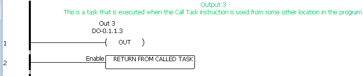
Here is the ladder logic for the task. Out3 will be on the first rung. The return form, called task instruction, will be on the second Run.
Note: You can tell the task’s name and location at the top of the programming window. In our case, the task is called Output 3 and is located in the folder Run When Called.
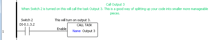
Create another task under the Run Every Scan folder. When switch 2 is on, the Call Task instruction will call the task Output 3 that we created above. This will turn output three on.
Note: Our program will turn the bit on, but we have not included any logic to turn the bit off.
Run Every Scan – Productivity Program Control
These tasks will run every scan of the PLC. Above, you will see how we used a task in this folder to execute tasks in the Run When Called folder.
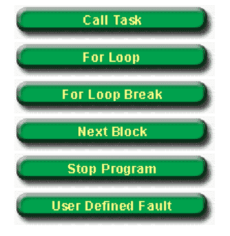
For / Next / Break Loop Instruction – Productivity Program Control
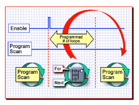
We can create a task that will execute lines of ladder code several times in one scan of the PLC. This is accomplished by using a for / next loop.
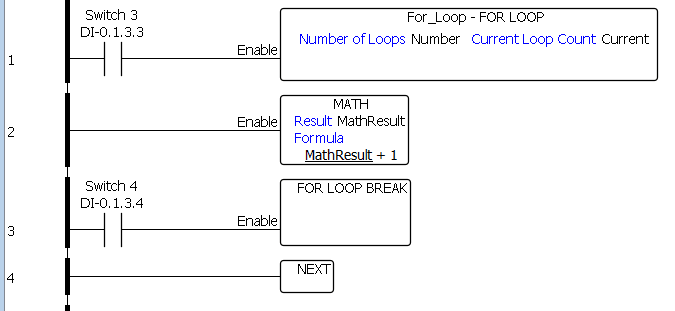
The ladder rungs between the For Loop and Next instructions are repeated for the number of times specified; For Loop Break instruction can be used to quit the looping for the scan.
You will see that when you run the MathResult tag will go to the highest number quickly. In our example, the math instruction will run 5000 times each scan. If the For Loop Break instruction is executed, the math instruction will only run once per scan. This will slow down the process.
Please see a demonstration of this below in the video.
Stop Program Instruction – Productivity Program Control
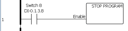
The stop program instruction will stop the execution of your logic.
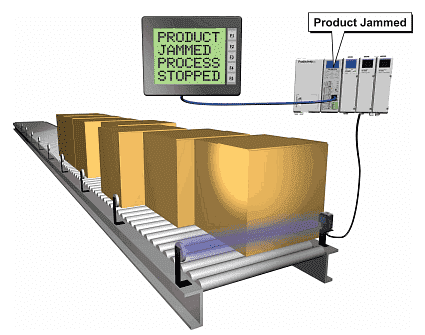
To start again, you need to cycle power to the CPU or use the switch on the CPU and turn it to Stop and then back to Run mode again.
User-Defined Fault – Productivity Program Control
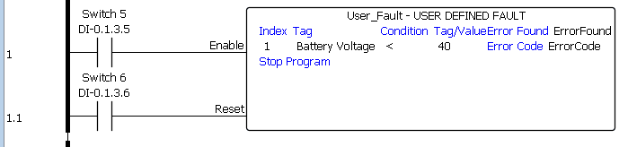
Using the user defined fault instruction we can Compare up to Eight Tags or Constant values against other Tags or Constant values and generate Faults or Stop Program based on the results.
In our example, we are comparing the battery voltage to the value of 40. This will generate a fault where we stop the program. To start again you need to cycle power to the CPU or use the switch on the CPU and turn it to Stop and then back to Run mode again.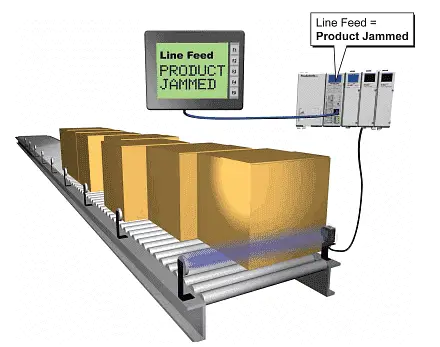
Disable Task – Productivity Program Control
Tasks that are located in this folder will not be executed. This is ideal for programming logic and then moving it into the program.
Task Library
The Task Library allows you to take a task from one project and use it in another project. This is helpful if common items are on your programming machines. See the help file in the productivity suite software.
Moving Tasks in the Task Management Window
The corresponding ladder logic will appear when we select a task in the task management window. Icons on the top of this window will delete, start a new window, etc.
If we click and hold the mouse button, a task can be moved around in the same or different folders.
Program control tasks are essential in your automation project. The productivity suite software provides several ways to manipulate your code for the desired result.
Download the PLC program here.
Watch the video below for the program control instructions we created for our Productivity 2000 Series PLC.
Productivity 2000 Series PLC from Automation Direct
Overview Link (Additional Information on the Unit)
Configuration (Configure and purchase a system – BOM)
User Manual and Inserts (Installation and Setup Guides)
Productivity Suite Overview (Features of the fully functional free software package for the Productivity Family of PLC (PAC) controllers)
Productivity Suite Programming Software (Free Download Link)
This software contains all the instructions and helps files for the Productivity Series.
Watch on YouTube: Productivity 2000 PLC Program Control
If you have any questions or need further information, please contact me.
Thank you,
Garry
If you’re like most of my readers, you’re committed to learning about technology. Numbering systems used in PLCs are not challenging to learn and understand. We will walk through the numbering systems used in PLCs. This includes Bits, decimals, Hexadecimal, ASCII, and Floating points.
To get this free article, subscribe to my free email newsletter.
Use the information to inform other people how numbering systems work. Sign up now.

The ‘Robust Data Logging for Free’ eBook is also available for free download. The link is included when you subscribe to ACC Automation.