To ensure the proper functioning of any PLC digital input, it is crucial to correctly test and wire the discrete inputs. By understanding the testing process and providing accurate wiring, we can guarantee the optimal performance of our PLC hardware.
Testing the inputs allows us to verify that they function as intended and that our wiring connections are secure. This step is essential in troubleshooting any potential issues and ensuring the reliability of our system.
Referring to the wiring diagram for the input card is important regarding wiring the inputs. Inputs for the PLC usually share a common point for wiring inputs like switches or sensors. The discrete inputs in our PLC are designed for direct current (DC) and can accept a 24-volt DC supply. The common point on the input wiring diagram can be either +24 or 0 volts DC, depending on the other inputs we are connecting to the PLC.
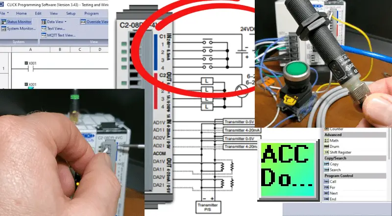
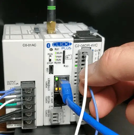
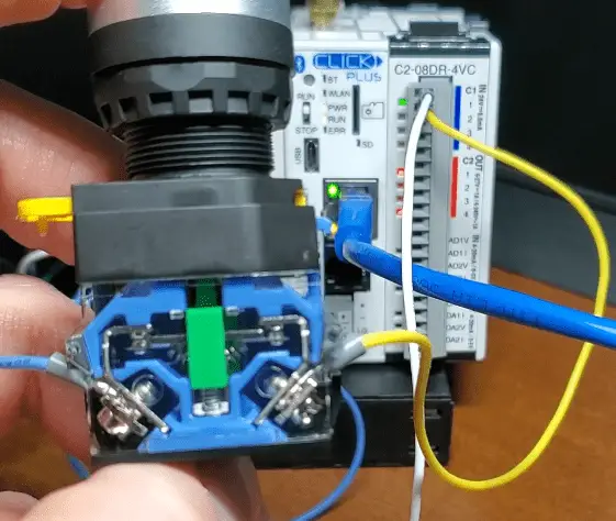
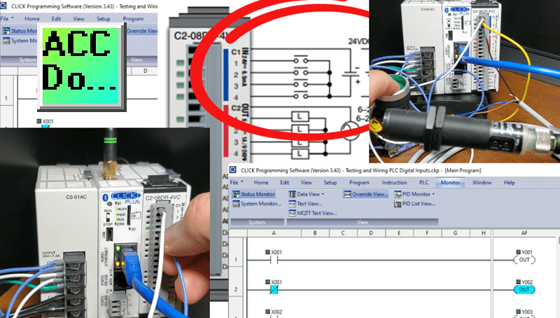
We will test the inputs of our Click PLUS PLC input module to ensure they are functioning correctly. Next, we’ll connect a pushbutton to the first PLC input and a 3-wire PNP DC sensor to the second input. Once the input is activated (24VDC), the corresponding indication light will turn on, confirming that our discrete PLC input works correctly. We can also monitor this on our free Click PLC programming software package.
By following these steps, we can ensure that our PLC digital inputs are adequately tested and wired, setting a solid foundation for the functionality of our system. Let’s now dive into the specifics of testing and wiring different types of inputs.
Testing the PLC Digital Inputs
To ensure the proper functioning of our Click PLUS PLC, it is crucial to test and wire the digital (discrete) inputs correctly. By understanding the testing process and ensuring accurate wiring, we can guarantee the optimal performance of our PLC hardware.
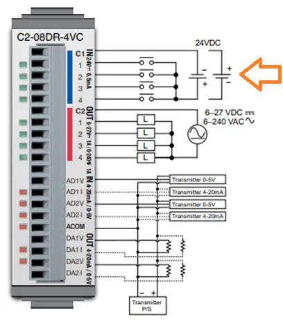
Start by looking at the wiring diagram for the input card, specifically for our C2-08DR-4VC CLICK PLUS Option Slot Module. You will notice that the discrete inputs are designed for direct current (DC) and can accept a 24-volt DC supply. The common point on the input wiring diagram can be either +24 or 0 volts DC, depending on the other inputs we are connecting to the PLC.
To test the inputs, we need to connect the common point of the inputs to either the +24 or 0-volt DC supply. Once this is done, we can touch the four input terminals with the other end of the circuit. In this setup, our PLC input acts as the load while we act as the switch for the input. When the input is activated, the indication light on the input will illuminate, confirming that our discrete PLC input is functioning correctly.
By following these steps, we can ensure that our PLC digital inputs are adequately tested and wired, setting a solid foundation for the functionality of our system. Watch the video below on testing the inputs. The following section will explore how to wire a pushbutton switch to our PLC input.
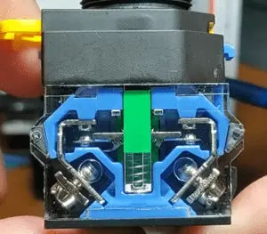
Wiring a Pushbutton Switch to our PLC Input
Pushbutton switches come in two configurations: normally open (NO) and normally closed (NC). The distinction lies in their default state when not pressed. A normally open switch is open or disconnected when not pressed and closes or connects when pressed. On the other hand, a normally closed switch is closed or connected when not pressed, and it opens or disconnects when pressed.
We will follow the wiring diagram to wire a pushbutton switch to our PLC input. We will create an electrical circuit loop by connecting the components in a specific order.
One side of the DC power supply will be connected to the common point of the PLC input. The first point of the PLC input will be connected to one side of the switch. Finally, the other side of the switch will be connected to the other side of the DC power supply, completing the circuit.
By wiring the pushbutton switch in this manner, we establish a connection that allows the flow of current when the switch is pressed. This configuration enables the PLC to detect the change in state and respond accordingly. Whether we use a normally open or normally closed switch depends on our system’s specific requirements and the input’s desired behavior. Watch the video below on wiring the pushbutton to the PLC input.
The following section will explore how to wire a proximity switch to our PLC input, providing an alternative method for detecting objects.
Wiring a Proximity Switch to our PLC Input
We will focus on a three-wire proximity sensor to wire a proximity switch to our PLC input, specifically the CK1-00-2H. This sensor can detect metallic and nonmetallic objects like liquid, plastic, paper, etc.
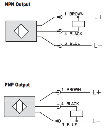
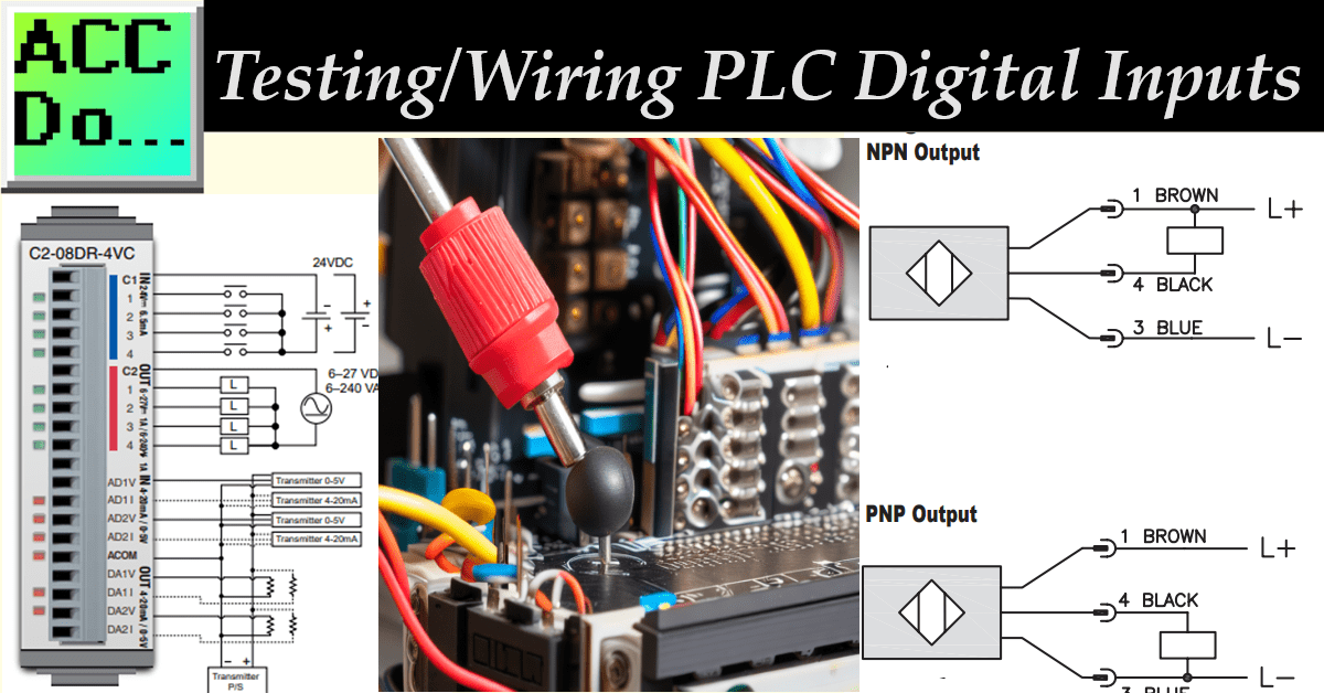
When examining this sensor’s wiring diagram, we can wire its output as either NPN (Negative Switching, Sinking) or PNP (Positive Switching, Sourcing). Since our common PLC input is wired to 0 volts DC, we will wire this sensor as a PNP output.
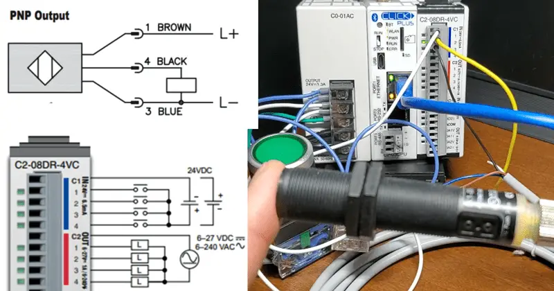
In the diagram, our PLC input serves as the load. The blue wire is connected to the 0-volt DC supply and wired to our common for the DC inputs on the PLC. On the other hand, the black wire acts as the switching wire and will be connected to the second input of the PLC, serving as the load. Lastly, the brown wire is connected to the +24 Volt DC supply.
It’s worth noting that in most 3-wire DC sensors, we need to wire in a power supply to provide the necessary power for the sensor to function. In contrast, our pushbutton switch utilizes the operator’s power to press the button.
Following this wiring configuration, we establish a connection that allows the proximity switch to detect objects and send the corresponding signal to the PLC input. This enables the PLC to respond accordingly based on the detected object.
Watch the video below on wiring the 3-wire proximity sensor to the PLC input and testing.
This article has covered the testing and wiring of PLC digital inputs. We discussed wiring a proximity switch to our PLC input, specifically focusing on a three-wire proximity sensor, the CK1-00-2H sensor. We learned that this sensor can detect both metallic and nonmetallic objects.
We could wire its output as NPN or PNP when wiring the proximity switch. We chose to wire it as a PNP output since our common PLC input is wired to 0 volts DC. We examined the wiring diagram and connected the proximity sensor to the PLC.
Understanding how to test and wire PLC digital inputs is crucial for ensuring the proper functioning of industrial automation systems. Following the guidelines and wiring diagrams, you can confidently integrate various input devices into your PLC system and enhance its overall performance.
Watch on YouTube: Testing and Wiring PLC Digital Inputs
PLC Beginner’s Guide to PLC Programming
There are many different PLC manufacturers with other hardware and software. All of the programmable logic controllers have similar basic features. Here is how I would approach learning about basic PLCs.
Once you are familiar with the basics of the PLC, you will then learn specifics for the controller you will be programming.
This is the easiest way to learn about PLC programming.
Here are the controllers that we have covered or are covering at ACC Automation:
Arduino Opta PLC
BRX Do-More Series (Do-More Designer Software + Simulator)
Productivity Series P1000 / P2000
Click PLC Series
Omron CP1H Series
Horner XL4 PLC Series
EasyPLC Software Suite is a complete PLC, HMI, and Machine Simulator Software package. See below to receive 10% off this software. This PLC learning package includes the following:
Easy PLC – PLC Simulation will allow programming in Ladder, Grafcet, Logic Blocks, or Script.
HMI System – Easily create a visual human-machine interface (HMI)
Machine Simulator – A virtual 3D world with real-time graphics and physical properties. PLC programs can be tested using the EasyPLC or through other interfaces. (Modbus RTU, TCP, etc.)
Machine Simulator Lite – Designed to run on Android Devices.
Machine Simulator VR – Virtual Reality comes to life so you can test, train, or practice your PLC programming.
Purchase your copy of this learning package for less than $95 USD for a single computer install or less than $110 USD to allow different computers.
Receive 10% off the investment by typing in ACC in the comment section when you order.
Learn PLC programming the easy way. Invest in yourself today.
Additional examples of PLC program development using the five steps.
Click PLC – Easy Transfer Line Programming – Video
Productivity PLC Simulator – Chain Conveyor MS – Video
Five Steps to PLC Program Development – Die Stamping
PLC Programming Example – Process Mixer
PLC Programming Example – Shift Register (Conveyor Reject)
PLC Programming Example – Paint Spraying
PLC Programming Example – Delay Starting of 7 Motors
PLC Programming Example – Pick and Place
PLC Programming Example – Sorting Station (Shift Register)
PLC Programming Example – Palletizer
If you have any questions or need further information, please contact me.
Thank you,
Garry
If you’re like most of my readers, you’re committed to learning about technology. Numbering systems used in PLCs are not challenging to learn and understand. We will walk through the numbering systems used in PLCs. This includes Bits, Decimals, Hexadecimal, ASCII, and Floating Points.
To get this free article, subscribe to my free email newsletter.
Use the information to inform other people how numbering systems work. Sign up now.

The ‘Robust Data Logging for Free’ eBook is also available as a free download. The link is included when you subscribe to ACC Automation.