The Ethernet Click PLC high-speed counter has seven different modes of operation. In Part 1 we discussed the High Speed Count Mode, Interval Measurement Mode,
Duration Measurement Mode and Frequency Measurement Mode.
This 100 kHz counter can accept Up, Down, Up/Down, Pulse/Direction, or Quadrature (with Z) inputs.
We will be looking at the last three different high-speed counter modes available in the click. (External Interrupt, Pulse Catch, Filter) This is all set up through a user-friendly graphical user interface. We will also combine the Frequency Measurement and the High-Speed Count in one application. Let’s get started!
Previously in this series we have discussed:
System Hardware – Video
Installing the Software – Video
Establish Communication – Video
Numbering System and Addressing – Video
Timers and Counters
– Counter Video
– Timer Video
Compare and Math Instructions – Video
Program Control Instructions – Video
Shift Register – Video
Drum Instruction – Video
Send and Receive Instructions – Video
AdvancedHMI Communiation – Video
Firmware Update – Video
HMI Rotary Encoder Dial Input – Video
High Speed Counting – Part 1
– High Speed Count Mode
– Interval Measurement Mode
– Duration Measurement Mode
– Frequency Measurement Mode
Our entire series can be found here.
https://accautomation.ca/series/click-plc/
All of the Click High Speed Counter programs can be downloaded at the end of the post.
Create an Analog Voltage Input Tester for a PLC – Video
Wiring Testing Analog PLC Input Click – Video
Modbus RTU Click PLC Master to BRX PLC Slave Communication – Video
The programming software and manuals can be downloaded from the Automation Direct website free of charge.
Click High Speed Input Hardware
Please see Click PLC High Speed Counting Part 1 for the information on the Dart PU Series pick-up and the wiring diagram into our Click PLC. This magnetic pick-up will provide 10 pulses per revolution.
Purchase on Ebay
Programming the High Speed Counter
As mentioned before, you must have Click Software 2.30 or higher along with the updated firmware of the Ethernet unit with DC inputs to program the high-speed counter(s).
Firmware Update – Video
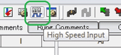
Select the High-Speed Input Icon from the main menu to get to the High-Speed Input Configuration window.
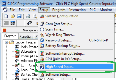
You can also select High Speed Input… from the main menu | Setup.
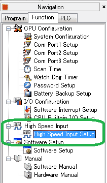
A third way to get to the High Speed Input Configuration window is to select High Speed Input Setup under the High Speed Input heading in the Function tab of the Navigation window.
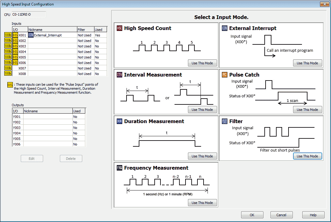
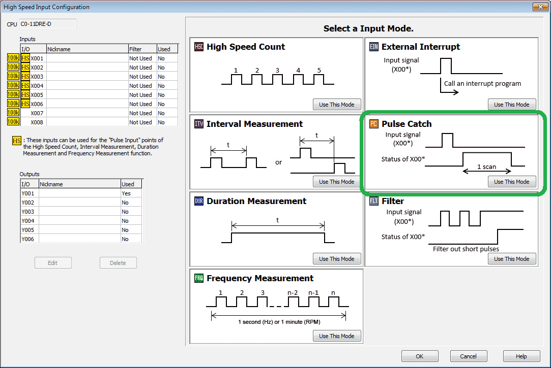
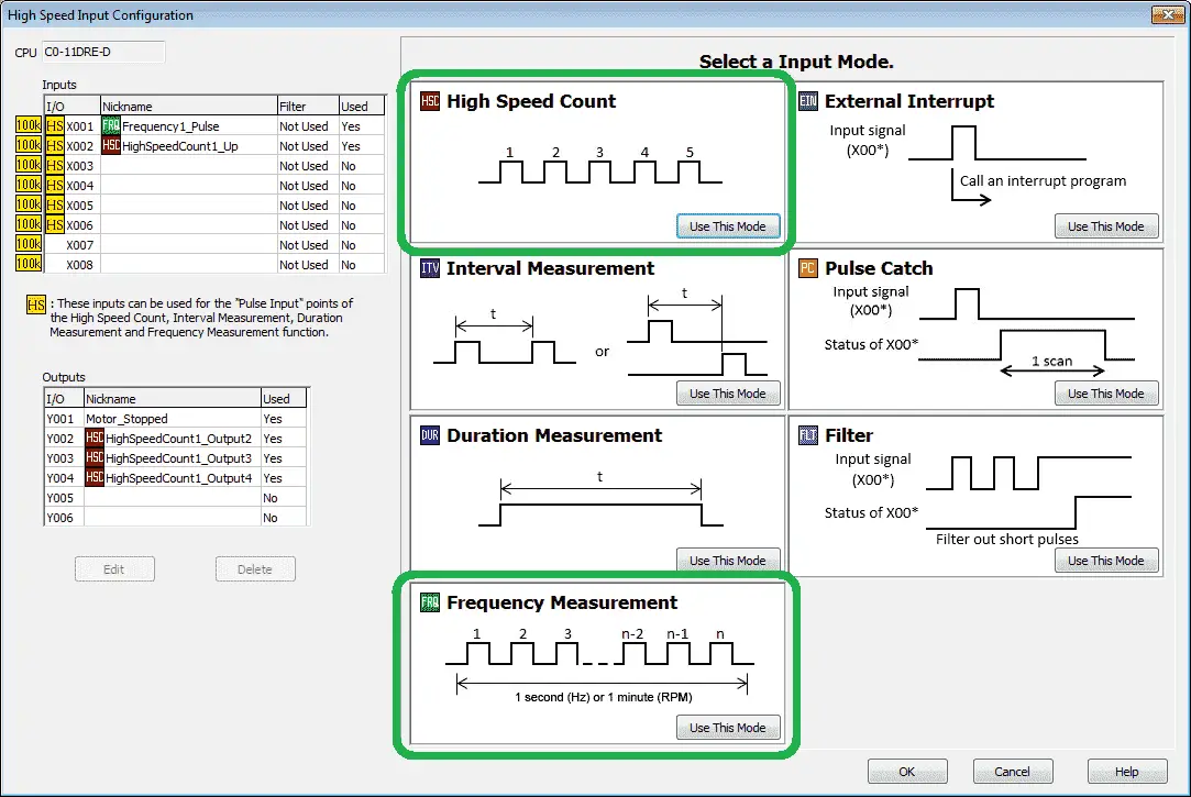
The High Speed Input Configuration window will now be displayed. This is where you will program all of the functions related to the high speed counter.
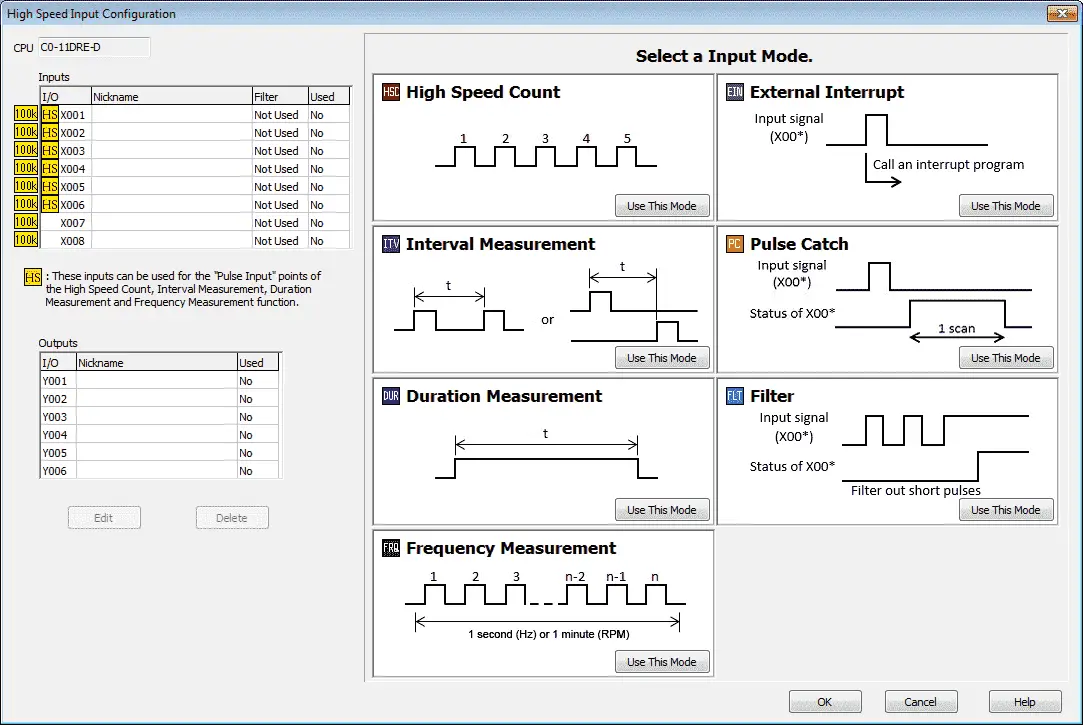
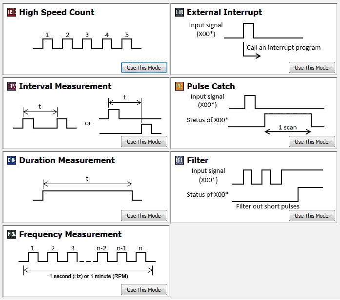
You will see the CPU inputs available for the high speed counter modes on the top left corner of the window. This is based on the selection of the Click CPU model number. Below them you will see the outputs available. All seven of the input modes for the high speed counter are indicated to the right along with a timing chart of the function.
Note: HS indication means that you can use all of the modes including the High Speed Count, Interval Measurement, Duration Measurement and Frequency Measurement functions on these inputs. Inputs not marked with HS can use the External Interrupt, Pulse Catch and Filter modes only.
External Interrupt Mode
This allows the setup of up to eight different Interrupt Programs triggered by External sources. You can use only the CPU Built-in discrete inputs as External Interrupts.
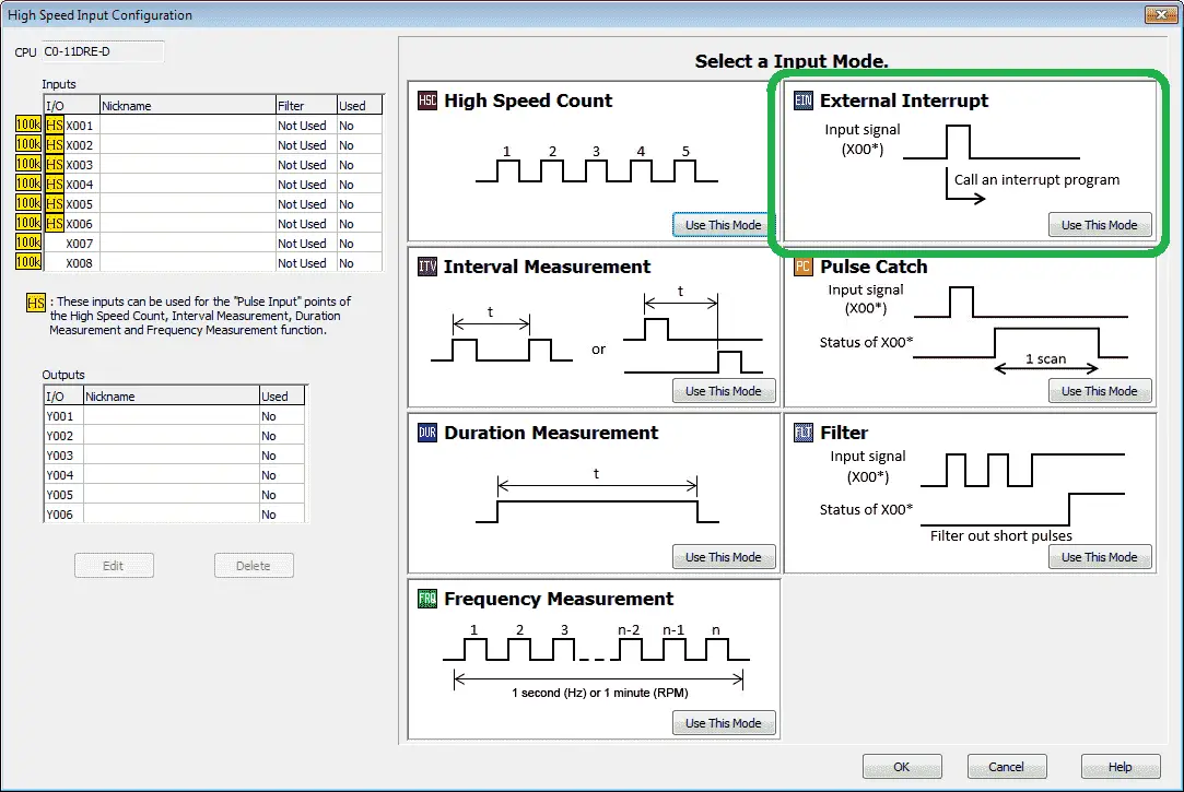
Select the ‘Use This Mode’ under the External Interrupt on the High Speed Input Configuration window.

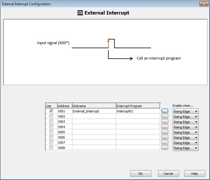
You will now see the External Interrupt Configuration window. A timing chart is displayed indicting the way in which this mode will operate based on the current selections. We will be leaving most of these settings as default.
Use : Select this to indicate all of the inputs that you want to use to trigger interrupt routines. In our case we will be using X001 to trigger Interrupt01.
Interrupt Program – This is the name of the interrupt program that will execute each time the input signal is present.
Enable when… – This can be selected for the Rising or Trailing edge of the input selected. We will leave this on the Rising Edge of X001.
Click OK
Here is our completed High Speed Count mode window. Select OK to save and exit.
Here is our completed High Speed Input Configuration window. You can quickly see that we have used X1 for our External_Interrupt.
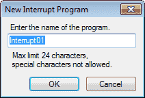
We can now create the logic in our interrupt named Interrupt01.
Note: If Interrupt01 routine did not exist, we could have hit the “…” on the External Interrupt configuration window to enter the new interrupt.
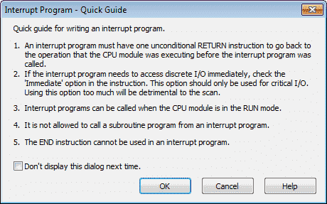
Here is the guide to creating an interrupt routine.
Here is the logic in our interrupt routine.
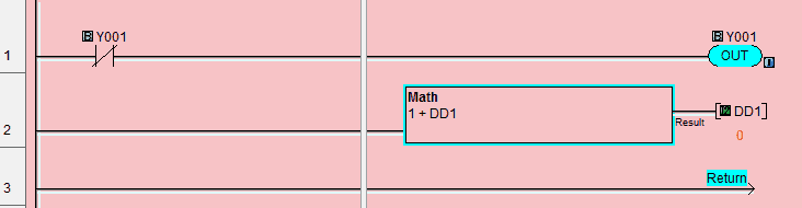
When output Y001 is not on, then Y001 is turned on. This means that every other call will alternate the output.
Notice that the output has a small ‘I’ located next to the output. This indicates that the output will immediately be set instead of waiting for the end of the PLC scan.
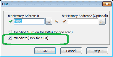
We must do this because the output may not get refreshed if two interrupts happen within the same scan.
The second line of code will count the number of times that the interrupts get executed. The result will be stored in register DD1.

This is the main program logic.
Watch the video below to see the external interrupt in action.
Watch on YouTube: Click PLC High Speed Counter External Interrupt Mode Video
Pulse Catch Mode
Pulse Catch mode of operation allows the ladder program to see an Input Pulse that is shorter in duration than the current scan time. The circuit latches the Input event on the selected Input for one scan and turns OFF after the scan.
Select the ‘Use This Mode’ under the Pulse Catch on the High Speed Input Configuration window.
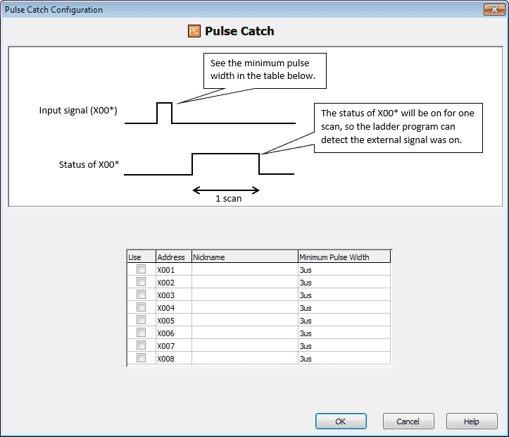
You will now see the pulse catch configuration mode menu. A timing chart is displayed indicting the way in which this mode operates.
Use: This is a check mark that is used to indicate what address will be used for the pulse catch.
Nickname: This is the name for the address that is to be used.
Minimum Pulse Width – This will indicate the minimum pulse width that must be seen in order for the PLC to pick up the input. (3us = 0.000003 seconds)
Watch the video below to see the pulse catch in action.
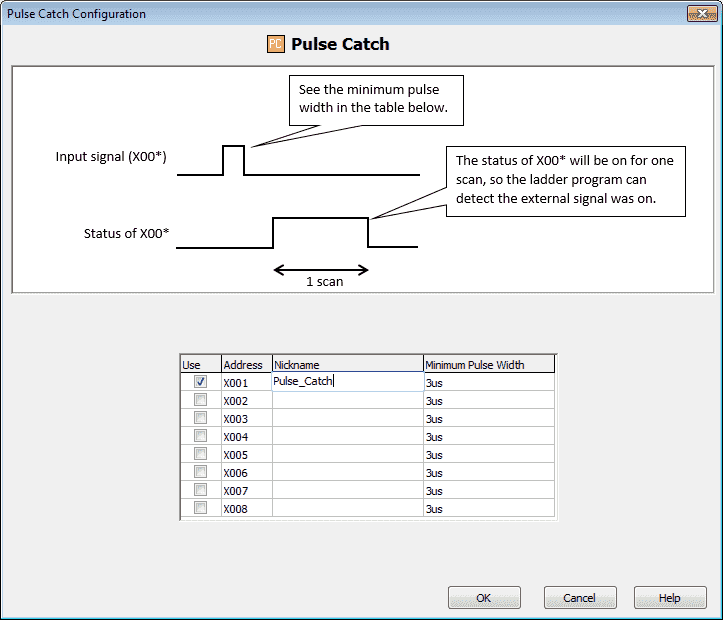
Here is the completed pulse catch configuration window. Select OK to save and return to the High Speed Input Configuration window.

You can quickly see that we are using X1 as our input for the pulse catch.

Our program will add one to register DD1 every time the pulse catch input is activated.
Notice that the input will be on for one scan.
Watch on YouTube : Click PLC High Speed Counter Pulse Catch Mode Video
Filter Pulse Mode
Click on the respective Input Filter selection to choose to set the specific Input to Filtered Input. Enter the Filter Time directly or click on the arrows to change the value in milliseconds. The valid setup range is 1 to 99 ms. When the Physical Input signal keeps its status for longer than the Filter Time, the status is copied to the Memory Address assigned to the Input.
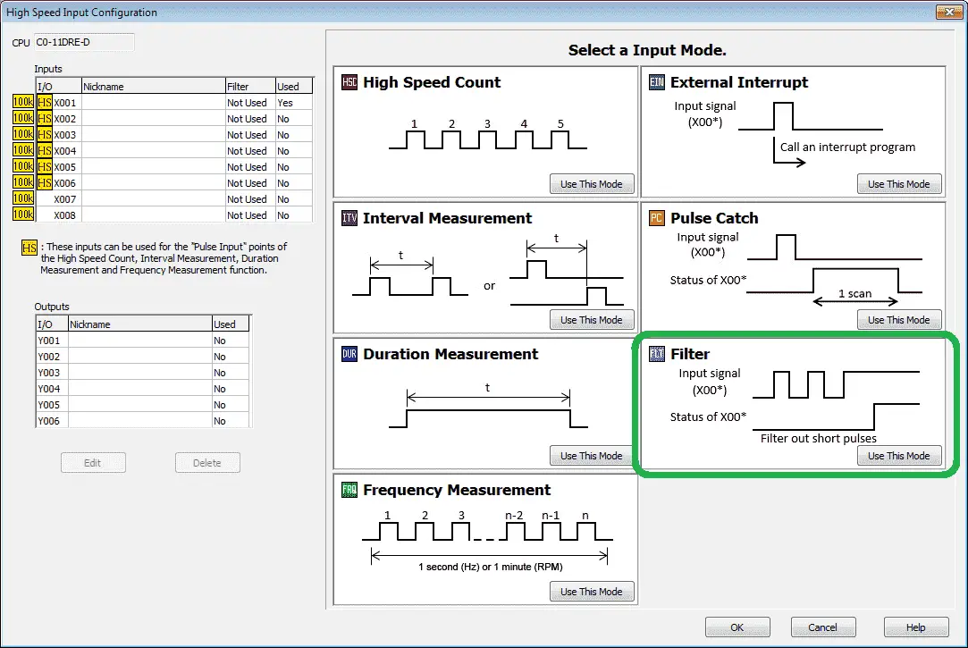
Select the ‘Use This Mode’ under the Filter on the High Speed Input Configuration window.
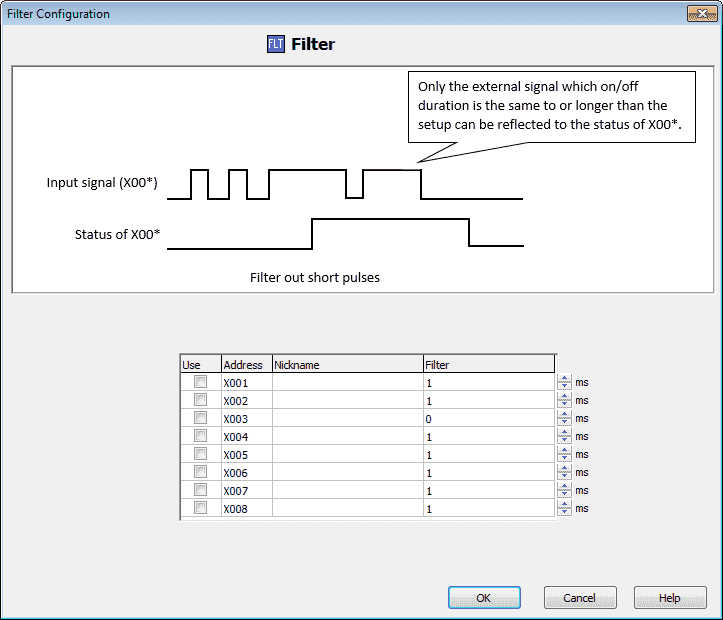
You will now see the filter configuration mode menu. A timing chart is displayed indicting the way in which this mode will operate.
Use : Check this to indicate what inputs will be used in the filter mode.
Nickname: Enter the name for the filter input selection. In our case we will call this Filter_Input (X001)
Filter – This is the time that the input must be on before it recognizes the input. In our case we will put this at 99ms.
Watch the video below to see the filter mode in action.
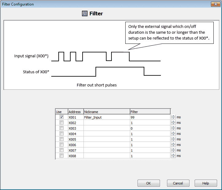
Here is the completed filter configuration window. Select OK to save and return to the High Speed Input Configuration window.
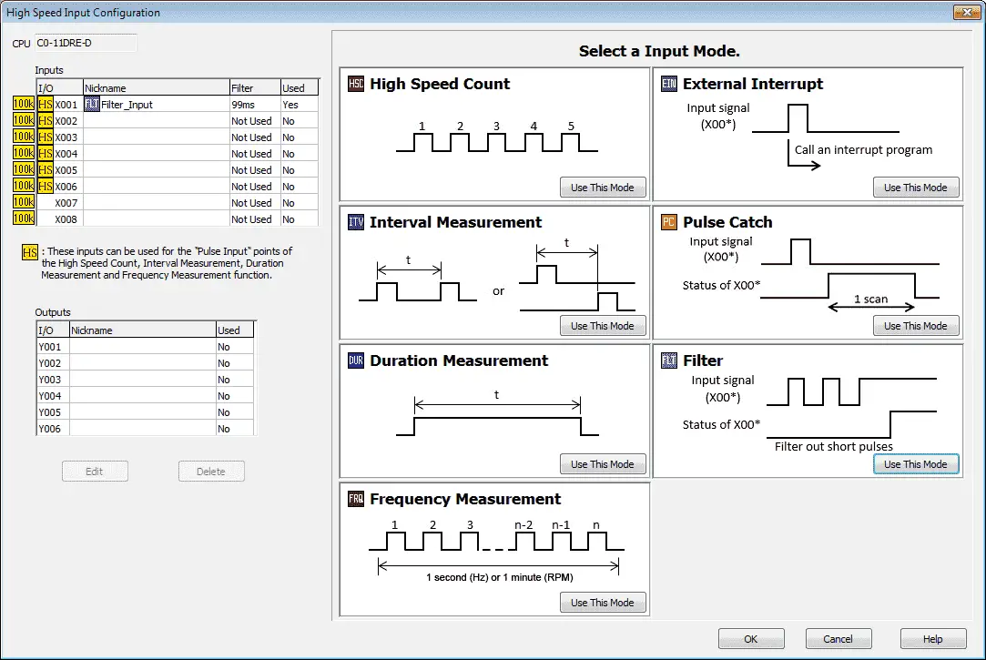
You can quickly see that we are using X1 as our input for the Filter mode.
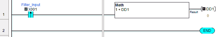
Our ladder logic in the main program will increment register DD1 every time that the input (X001) is longer than 99ms in length.
Watch on YouTube : Click PLC High Speed Counter Filter Pulse Mode Video
Frequency Measurement and High Speed Count Mode
We will now combine the frequency measurement and the high speed count mode for our last example. A quick review of these two modes can be found in part 1 of this post.

We will wire the same Dart PU-E output to input X1 and X2. In our example C1 is wired to the +24VDC supply along with the red wire of the PU-20E. The black wire of the PU-20E is connected to the 0VDC and the white (switching) wire is wired to our first two inputs. (X1 / X2).
Our Frequency Measurement will be set for RPM on input X001. The number of pulses per revolution will be set to 10 in our case.
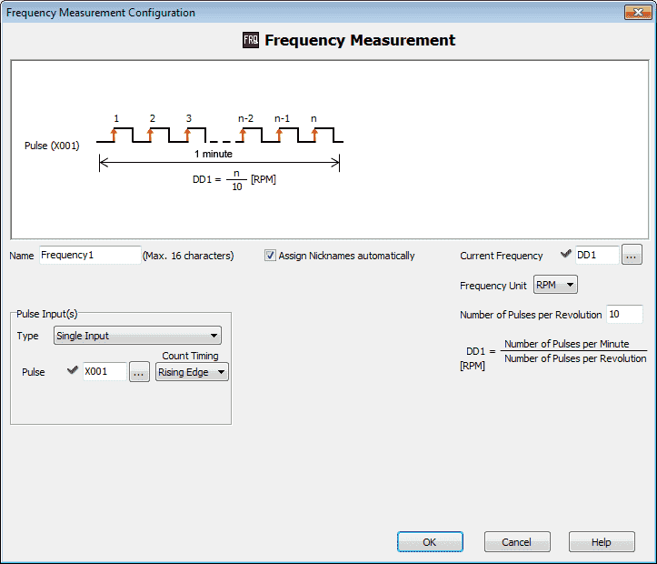
The frequency will be written to register DD1.
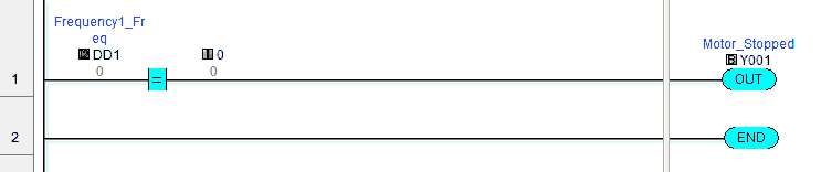
Our output Y001 will turn on when the frequency is equal to 0. This will indicate that the motor has come to a stop.
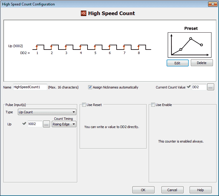
Our high speed count will be used on the rising edge of X002. The current value will be placed in register DD2.
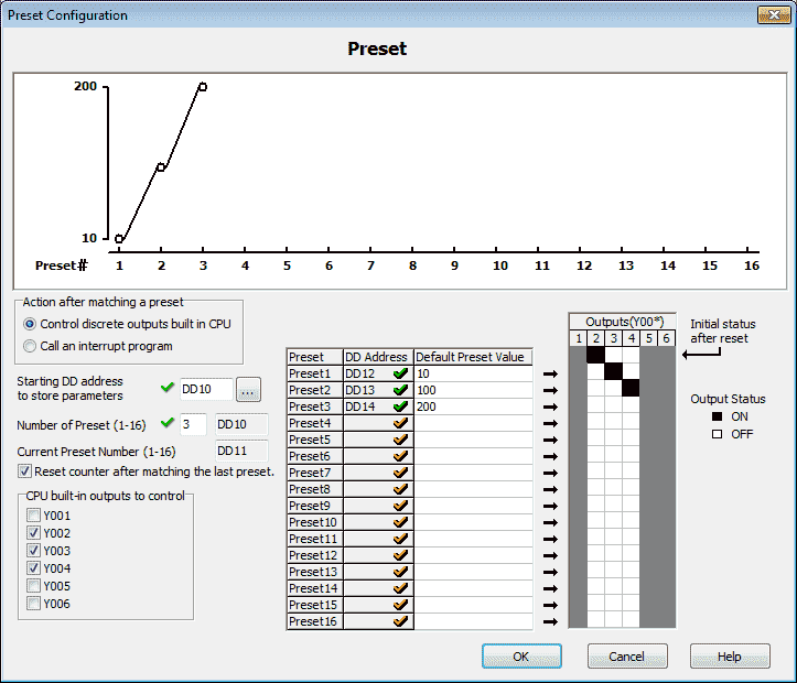
The Preset will be set as follows:
Control discrete outputs built in CPU
Starting DD address to store parameters – DD10
Number of Preset – 3
Reset counter after matching the last preset.
We will use Y002, Y003 and Y004.
Preset 1 – DD12 – 10
Preset 2 – DD13 – 100
Preset 3 – DD14 – 200
Note the pattern of outputs that we have set in the picture above. Y002 will be on from 0 to 10 on the count. Y003 will be on from 10 to 100 on the count. Y004 will be on from 100 to 200 on the count.
Watch the video below to see the frequency measurement and high speed count in action.
Watch on YouTube : Click PLC High Speed Counter Frequency Measurement and High Speed Count Mode Video
Download the Click PLC programs here.
Click PLC Support Links
The Click PLC can be programmed using free Click programming software from Automation Direct. Here is a link for the software.
https://support.automationdirect.com/products/clickplcs.html
The following links will help you to install the software and establish communication.
https://accautomation.ca/click-plc-installing-the-software/
https://accautomation.ca/click-plc-establish-communication/
The entire Click PLC series can be found at the following URL:
https://accautomation.ca/series/click-plc/
If you have any questions or need further information please contact me.
Thank you,
Garry
If you’re like most of my readers, you’re committed to learning about technology. Numbering systems used in PLC’s are not difficult to learn and understand. We will walk through the numbering systems used in PLCs. This includes Bits, Decimal, Hexadecimal, ASCII and Floating Point.
To get this free article, subscribe to my free email newsletter.
Use the information to inform other people how numbering systems work. Sign up now.

The ‘Robust Data Logging for Free’ eBook is also available as a free download. The link is included when you subscribe to ACC Automation.