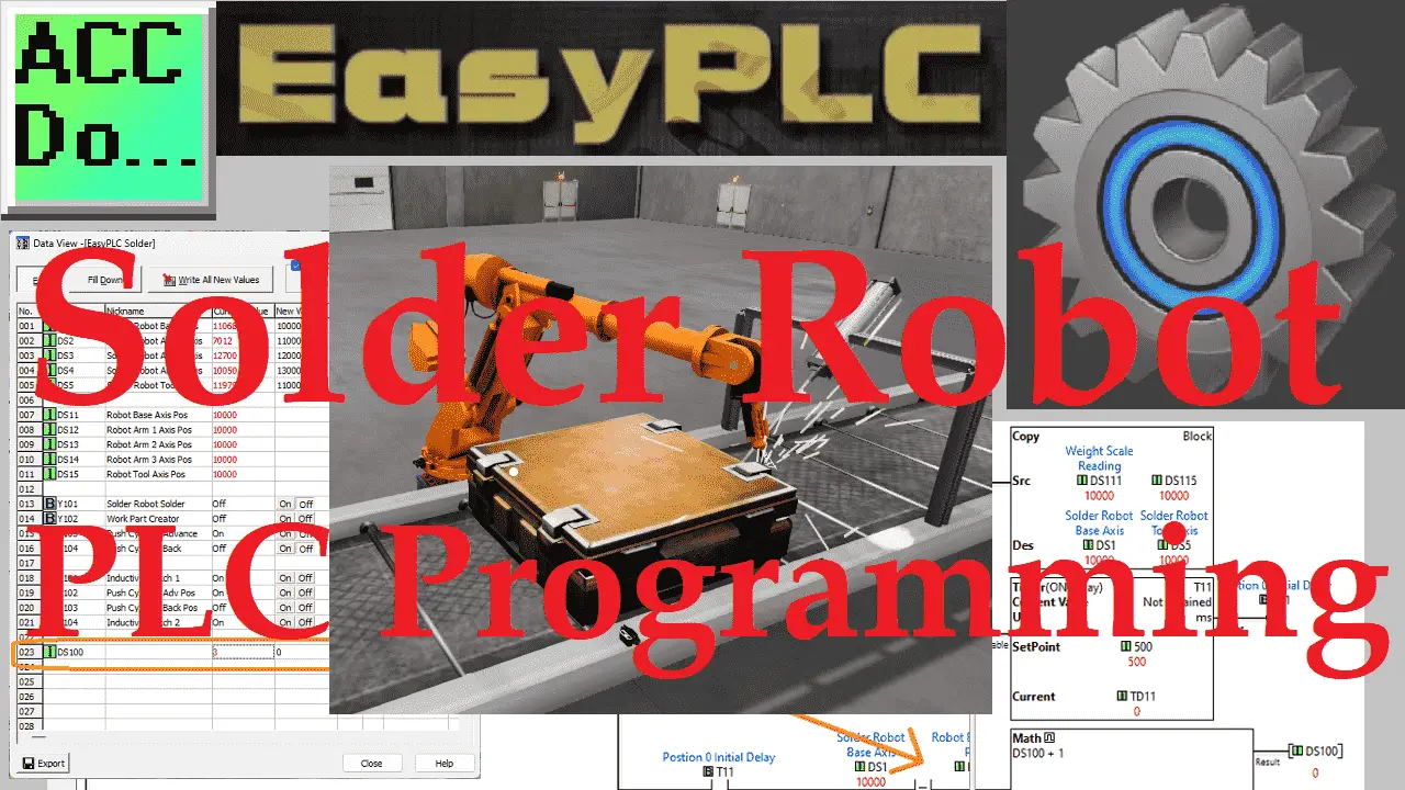
The Machine Simulator (MS) is part of the EasyPLC software suite. It has many built-in machines that are used to show different programming techniques. The solder robot example is one of these machines. This will demonstrate a sequencer robot example. In this case, four rivets are welded using a robot. The logic will step through various steps to perform the task.
 We will use a Click PLUS PLC and the Click programming software to program this EasyPLC simulator solder robot. This will be done using Modbus TCP (Ethernet) for communications. The program will control the stopping and welding of the boxes. Using the five steps for program development, we will show how this sequencer is programmed. Let’s get started.
Learn PLC programming the easy way. See below how to receive a 10% discount on this already cost-effective learning tool. Invest in yourself today.
Previously we have done the following:
Easy PLC Installing the Software – Video
EasyPLC Software Suite – Quick Start – Video
Click PLC – Easy Transfer Line Programming – Video
Productivity PLC Simulator – Chain Conveyor MS – Video
Do-More PLC – EasyPLC Box Selection Program – Video
Click PLC EasyPLC Gantry Simulator – Video
Click PLC Simple Conveyor EasyPLC – Video
EasyPLC Paint Line Bit Shift – BRX Do-More PLC – Video
Click PLC – EasyPLC PLC Mixer Programming – Video
Click PLC EasyPLC Warehouse Stacker Example – Video
– Operation Video
EasyPLC Machine Simulator Productivity PLC Robotic Cell – Video
EasyPLC Simulator Robotic Cell Click PLC – Video
EasyPLC Simulator Robotic Cell BRX Do-More PLC – Video
– EasyPLC Factory Editor Robotic Cell Additions Video
4 Way Traffic Light PLC Program EasyPLC – Video
Rock Crusher Plant EasyPLC BRX Do-More – Video
Freight Carrier Weighing and Distribution EasyPLC – Video
EasyPLC Machining Center Loading Robots – Video
EasyPLC Palletizing Robot Programming Click PLC – Video
EasyPLC Machine Editor – Design a Simulation – Video
PLC Programming Mixing Tank – EasyPLC / Do-More – Video
Define the task: (Step 1 – Solder Robot PLC Program)
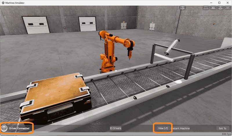
The first step of PLC program development is determining what must be done. Start the EasyPLC Machine Simulator (MS). Select the start button on the main page or select machines from the main menu on the top of the machines simulator window.
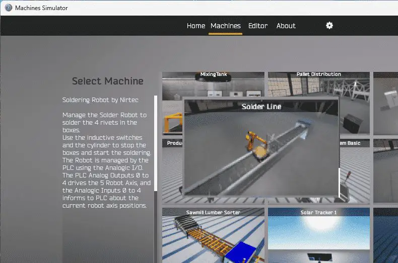 All the available machines will now be displayed. Click on the “Solder Line.” This is the example that we will be programming. To the left of the screen, information will be displayed on what the machine needs to do as well as the inputs and outputs required for the program.
Manage the soldering Robot to solder the four rivets in the boxes. Use the inductive switches and the cylinder to stop the boxes and start the soldering. The Robot is managed by the PLC using analog inputs and outputs. The PLC analog outputs 0 to 4 drive the 5-axis robot. Analog inputs 0 to 4 inform the PLC about the current robot axis positions.
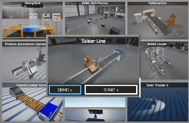 The machine simulator has a demo mode for the built-in machines. Select the demo mode for the soldering Robot. This will allow you to watch the operation of the solder robotic.
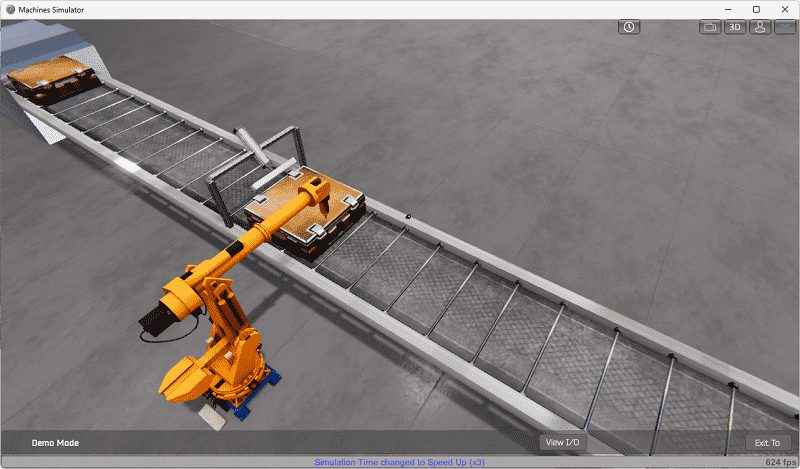
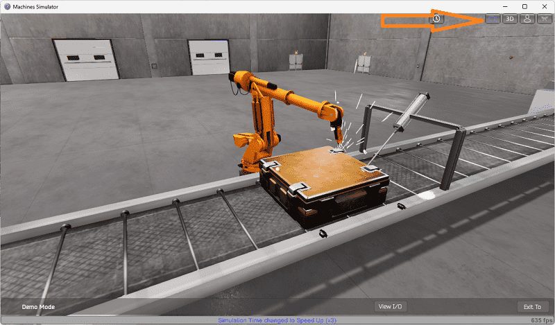 The solder robot demo mode will operate, showing you the basics of operation.
 Move around the 3D virtual environment. Three icons on the top of the window will allow you to move around this 3D environment. The first icon is the default selection. This will enable you to move around without bumping into the components. The last icon will automatically show you around this virtual environment. The first-person mode will mimic a person in your 3D learning world. Once we understand what must be done, we can move on to the next development step in the PLC program.
Define the Inputs and Outputs: (Step 2 – Solder Robot PLC Program)
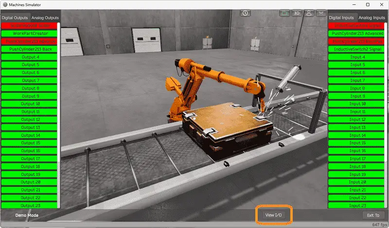
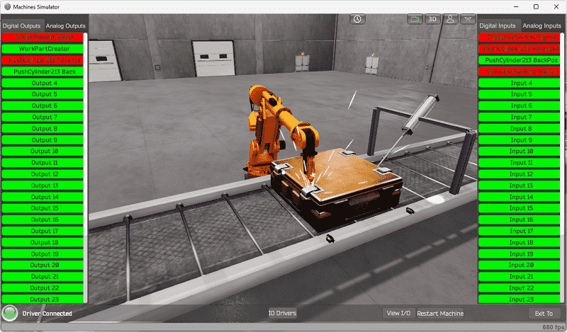
The View IO at the bottom of the machine simulator window will display the inputs and outputs required for this solder robot example. While still in demo mode, you can see the operation of the digital inputs and outputs.
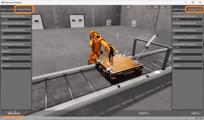
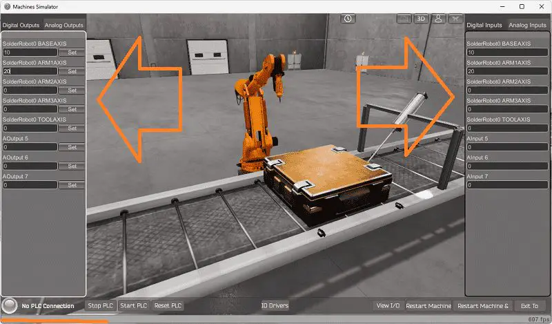
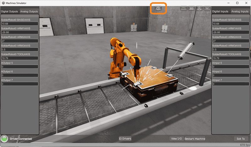
 Select the analog inputs and outputs to see the control of the five-axis Robot.
 Use the following PLC signals to move the Robot:
PLC Digital Outputs:
1 – Solder – This will turn on the robot welder output
2 – Work Part Creator – This will force the conveyor and make a box.
3 – Push Cylinder Advance – This will extend the cylinder to stop the box in position to weld.
4 – Push Cylinder Back – This will retract the cylinder to allow the finished welded box to continue on the conveyor.
PLC Digital Inputs:
1 – Inductive Switch 1 – This is closest to the cylinder and will detect the box for the position on the conveyor.
2 – Push Cylinder Advanced – This extended sensor will determine the position of the cylinder.
3 – Push Cylinder Back – This retract sensor on the cylinder determines its function.
4 – Inductive Switch 2 – This is the first sensor the box will activate as it moves along the conveyor. It is used for positioning the box.
PLC analog outputs control the position of the Robot. The analog inputs report the current position of the Robot.
The EasyPLC solder robot example will require four digital outputs and four digital inputs.
Start the soldering Robot in Start mode if you are unsure what the output or input is.
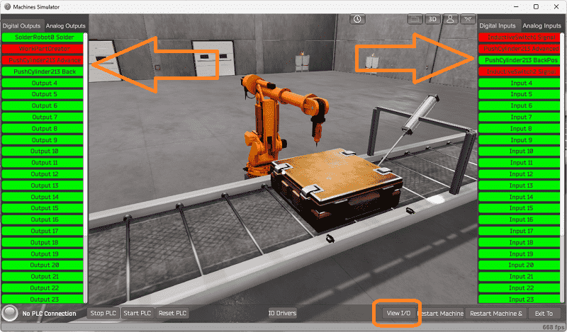 Select the View IO on the bottom middle of the machine simulator window. You can manually run the solder robot application without any control or PLC connection.
 Clicking on the outputs will allow you to turn them on manually. You can then monitor the inputs to see their operation. The restart button on the bottom of the machine simulator window will reset the scene back to the start.
The following table will define the inputs and outputs (IO) and Modbus addresses in the Click PLC that we will use for this program.
| Digital Type | Description | Click PLC Modbus Address | Machine Simulator Modbus Address |
| PLC Output – MS Input | Solder Robot Solder | Y101 – 8225 | 8224 |
| PLC Output – MS Input | Work Part Creator | Y102 – 8226 | 8225 |
| PLC Output – MS Input | Push Cylinder Advance | Y103 – 8227 | 8226 |
| PLC Output – MS Input | Push Cylinder Back | Y104 – 8228 | 8227 |
| Analog | |||
| PLC Output – MS Input | Solder Robot Base Axis | DS1 – 40001 | 0 |
| PLC Output – MS Input | Solder Robot Arm 1 Axis | DS2 – 40002 | 1 |
| PLC Output – MS Input | Solder Robot Arm 2 Axis | DS3 – 40003 | 2 |
| PLC Output – MS Input | Solder Robot Arm 3 Axis | DS4 – 40004 | 3 |
| PLC Output – MS Input | Solder Robot Tool Axis | DS5 – 40005 | 4 |
| PLC Input – MS Output | Inductive Switch 1 | X101 – 100033 | 32 |
| PLC Input – MS Output | Push Cylinder Adv Pos | X102 – 100034 | 33 |
| PLC Input – MS Output | Push Cylinder Back Pos | X103 – 100035 | 34 |
| PLC Input – MS Output | Inductive Switch 2 | X104 – 100036 | 35 |
| Analog | |||
| PLC Input – MS Output | Robot Base Axis Pos | DS11 – 40011 | 10 |
| PLC Input – MS Output | Robot Arm 1 Axis Pos | DS12 – 40012 | 11 |
| PLC Input – MS Output | Robot Arm 2 Axis Pos | DS13 – 40013 | 12 |
| PLC Input – MS Output | Robot Arm 3 Axis Pos | DS14 – 40014 | 13 |
| PLC Input – MS Output | Robot Tool Axis Pos | DS15 – 40015 | 14 |
Note: The machine simulator will be offset by one on the Modbus Addresses. See the video below for the demo mode and determining inputs and outputs.
Develop a logical sequence of operation: (Step 3 – Solder Robot PLC Program)
A flow chart, sequence table, or detailed sequence description is used to fully understand the process that needs to be controlled. It must also answer questions like the following:
What happens when electrical power and pneumatic air is lost? What happens when the input/output devices fail? Do we need redundancy?
 This step is where you will spend most of your time. Understanding everything about the operation will save you time. It will help prevent you from continuously re-writing the PLC program logic. Knowing all these answers upfront is vital in developing the PLC program.
The solder robot machine will turn on the part creator (start conveyor) if the conveyor proximity sensors do not detect a box or the current box welded rivets have been completed. The cylinder will extend as the box is detected on inductive switch 2. The part creator output will remain to position the box between the two inductive switches. The Robot will be in the home position.
Once the box is in the correct position, the Robot will move to the first rivet position. Once this has been verified with the analog input, the solder (weld) output will be activated for 3 seconds.
When the welding is complete, return the Robot to the home position. Once verified in the home position, move the Robot to the second rivet position and repeat the welding for 3 seconds.
This operation will repeat until all of the rivets have been welded. The Robot will return home after each of the weld operations.
Once all the rivets have been welded, the Robot will return home, and the cylinder will retract. The box is complete, and the conveyor (part creator) will start sending the finished box down the conveyor, allowing a new package to be positioned. This cycle will continually cycle.
A PLC programmer must know everything about the sequence and operation of the machine before programming.
Ask questions or View existing documentation to ensure you know the logical steps to the machine’s operation.
Develop the Click PLC program: (Step 4 – Solder Robot PLC Program)
Writing the ladder logic code for the PLC example will be the next step in our program development. We will be using the Click programming software with the Click PLUS PLC.
The Click Series will take you through installing the program, communicating with the controller, providing instructions, and addressing the controller.
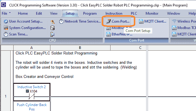 Select the Com Port under the main menu | Setup.
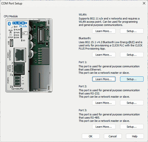 Select the setup on Port 1, which is the Ethernet port.
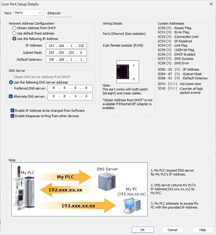 Please make a note of the static IP address that we are using for the Click PLC. This will be used later to connect to the EasyPLC machine simulator.
Close these windows and click on the Modbus TCP Setup.
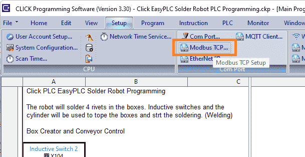 This is located on the main menu | Setup.
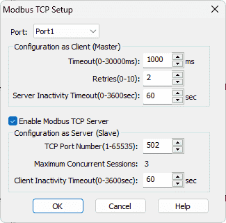 The enable Modbus TCP Server is selected by default. Ensure that this is chosen so the EasyPLC Machine Simulator can communicate to the Click PLC on the default 502 port. Select OK.
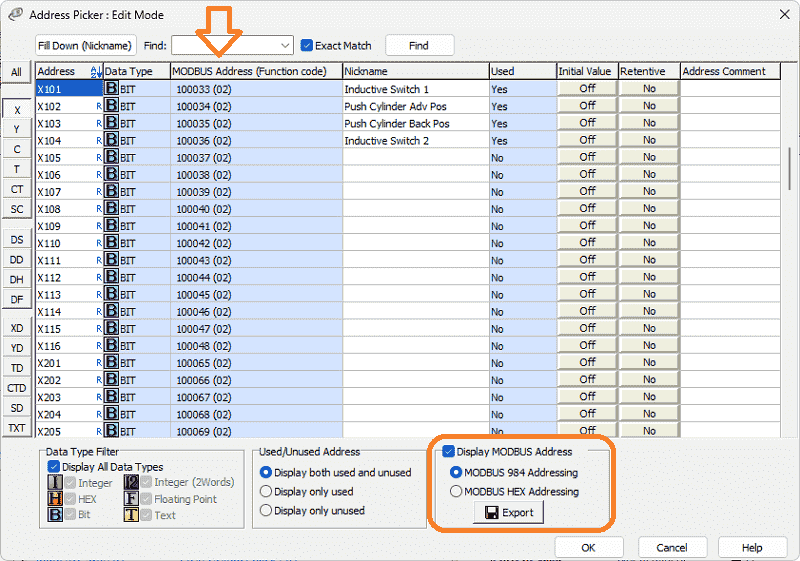
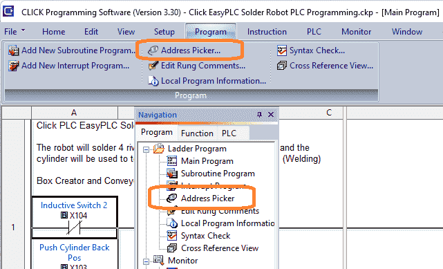 Using the address picker, select X101. Select the display Modbus address on the bottom right-hand side. This will show you the Modbus addresses for the inputs from the EasyPLC machine simulator.
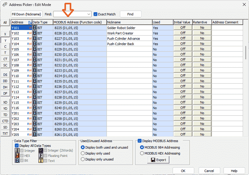
 The output Modbus addresses to the EasyPLC machine simulator can be seen by selecting Y101.
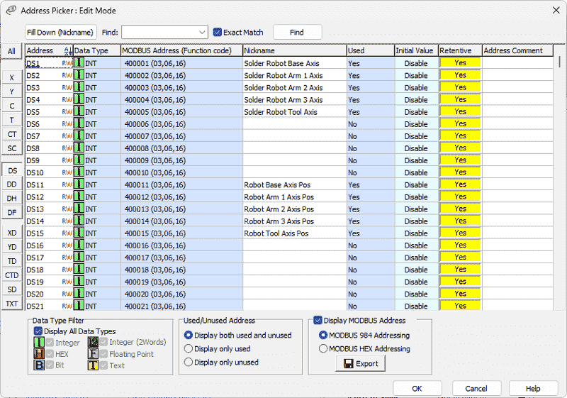
 DS1 to DS5 will control the Robot. DS11 to DS15 will report back the position of the robot. Here are the Modbus addresses.
 We will need these Modbus addresses when we test our PLC ladder logic in the next step of our program development.
Solder Robot Click PLC Ladder Logic
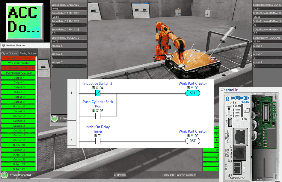
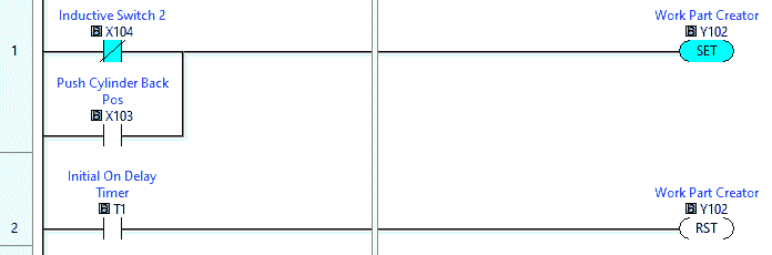 The first two lines of ladder logic will control the box creator and the conveyor. This output will do both functions.
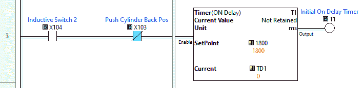 A time delay is used when switch 2 is made and the conveyor turns off. This will give enough time to align the box between the two switches.
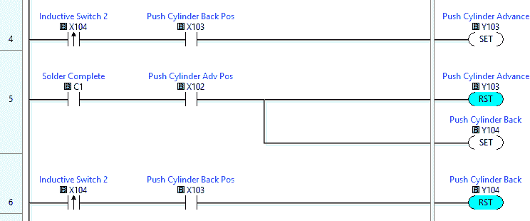 Ladder rungs 4 to 6 will control the push pneumatic cylinder. The cylinder will extend on the leading edge of switch 2 and retract on the “Solder Complete” bit.
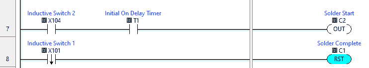 The solder start bit will control when the Robot starts the soldering sequence. Solder Complete bit will reset on the trailing edge of switch 1.
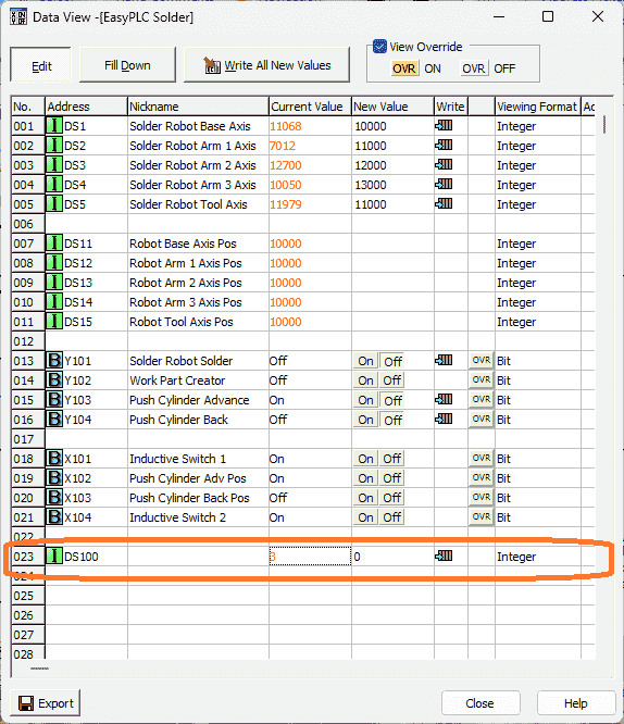
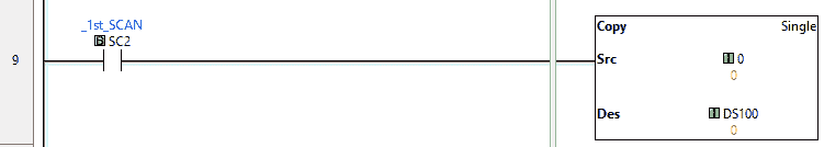 DS100 is used to track the current sequence number of the robot. Upon the first scan of the PLC, this will reset the logic to the initial position of 0. This is the robot’s home position.
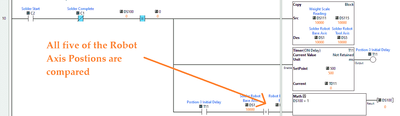 When we have the “Solder Start” signal and the box welding is not complete, we look to see the position counter. The home position parameters are then copied to the robot output. A time delay of 0.5 seconds is used to ensure that the robot has had a chance to change its position. Each robot axis is compared to the home position. If they are all equal, then the robot sequence is incremented by 1.
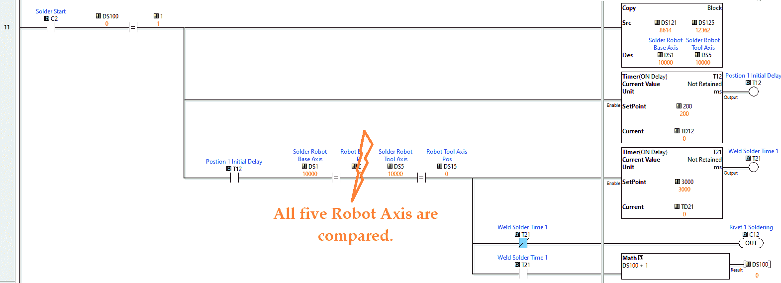 At position 1, the values are copied into the robot output registers. A delay of 0.2 milliseconds allows the robot to move the five-axis. Comparing each of the robot axis positions will then start a timer. This will turn an internal bit on for the duration. The internal bit will be used later to turn on the solder output. Once this welding time has expired, the robot will move to position 2. This is the robot’s home position again. This pattern repeats until all of the rivets have been welded. Once the rivets have been welded and the robot is at home, the “Solder Complete” bit will be set. This will move the completed box down the conveyor, and a new one can now be welded.
Modbus address registers are a 16-bit value. We see the following for the first rivet position in the machine simulator demo mode.
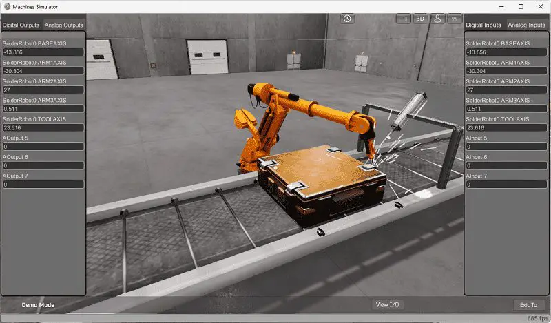 The value -13.856 will not translate using Modbus. The EasyPLC Machine Simulator Modbus driver can correct this value so we can communicate to any Modbus-capable controller.
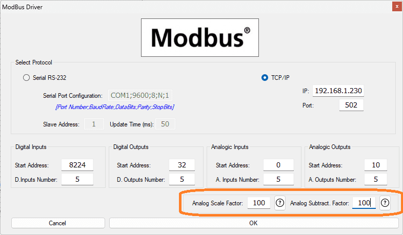 There are parameters that can be used for the analog values using the Modbus driver. The formula that is used is:
(Analog Subtract + Analog MS Value) * Analog Scaled Value
So the value of -13.856 from a Modbus capable PLC would be:
100 – 13.856 * 100 = 8614
The home position value of 0 in the machine simulator would be:
(100 + 0) * 100 = 10000
This ability in the EasyPLC Mobus Driver allows all of the test scenes in the machine simulator to be programmed.
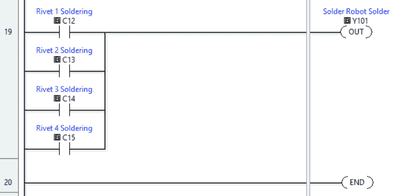 The last rung of the program will take each of the internal bits triggered by individual timers during the sequence and control the solder output.
Save and transfer the PLC program to the Click PLUS PLC. Ensure that the PLC is in Run mode.
Watch the video below to see this PLC program in action
Test the program: (Step 5 – Solder Robot PLC Program)
We will use Modbus TCP on our Click PLUS PLC to communicate with the EasyPLC Machine Simulator.
Call up the solder robot machine simulator in start mode.
 The status of the machine simulator will be at the bottom of the screen. Currently, we have no PLC connected. Select IO Drivers on the bottom middle of the screen.
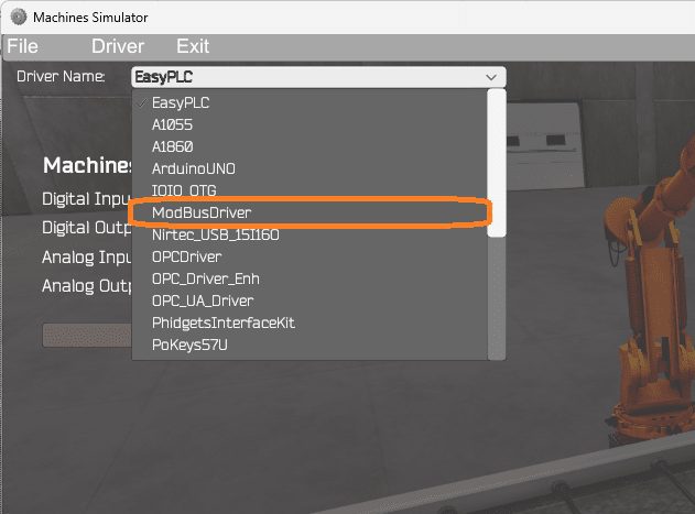 The EasyPLC driver is selected by default. Under the driver pull-down menu, select “ModBusDriver.” This driver will communicate Modbus TCP (Ethernet) and Modbus RTU (Serial). Select the down arrow on the driver’s name.
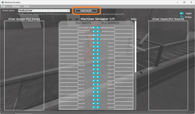 Select the configure button.
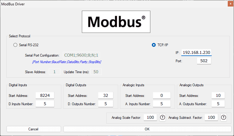 We can now enter the information for our Modbus driver. Select TCP/IP. This means the Ethernet port on the computer will communicate with the PLC.
The digital inputs from MS to the Click PLUS PLC will be 8225 to 8229. This will start at address 8224 due to the offset of 1. Digital outputs from MS to the Click PLUS PLC will be 100033 to 100037. This will begin with address 32 due to the offset of 1. Analog input values will begin at 400001 and output values at 400011. This will start at 0 and 10 due to the offset. Select the OK button.
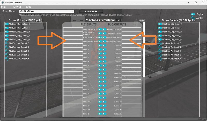 You will now see the inputs and outputs specified for the Modbus driver. We can manually assign the driver outputs to the PLC inputs and the driver inputs to the PLC outputs. However, the automatic assignment works well and will save you time.
Select Automatic Assignment from the driver option in the main menu.
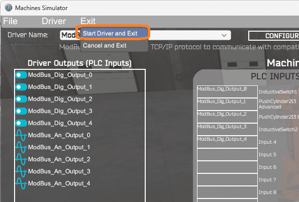
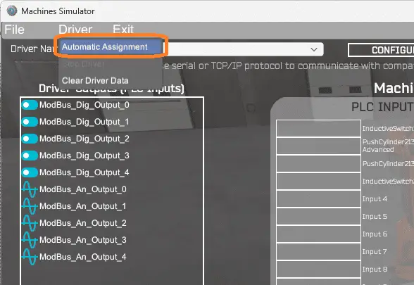 This will automatically assign the PLC IO to the Machine Simulator IO. Select start driver and exit from the main menu.
 On the bottom left side of the window, you will see that the driver communicates to the PLC with the green light. Select view IO to know the input and output status of the machine simulator.
 Ensure that the PLC is in run mode. We can see the operation of our EasyPLC Solder Robot.
 The digital inputs and outputs of the MS will correspond to the PLC controller.
Using Machine Simulator (MS) to test the program will ensure that our program works. Use the time speed to speed up the robot welder. Test for all circumstances. If modifications are required, we can easily go back to any previous steps and correct them.
 We can also watch the inputs and output operations using the Data View window of the Click PLC programming software.
Watch the video below to see this operation.
Here are some challenges for you and this EasyPLC solder robot simulation. This will help you to develop your PLC programming skills.
– Add a Start / Stop control panel to the simulation.
– Count the number of boxes welded and calculate the welding rate.
Let me know how you made out in the comments below.
Download the Click PLC sample program here.
Watch the video below to see the five steps of program development applied to the solder robot machine. The machine simulator is one of the best applications to help you learn PLC programming.
EasyPLC Software Suite is a complete PLC, HMI, and Machine Simulator package. This PLC learning package includes the following:
Easy PLC – PLC Simulation allows programming in Ladder, Grafcet, Logic Blocks, or Script.
HMI System – Easily create a visual human-machine interface (HMI)
Machine Simulator – A virtual 3D world with real-time graphics and physical properties. PLC programs can be tested using EasyPLC or through other interfaces. (Modbus RTU, TCP, etc.)
Machine Simulator Lite – Designed to run on Android Devices.
Machine Simulator VR – Virtual Reality comes to life so you can test, train or practice your PLC programming.
Purchase your copy of this learning package for less than USD 75 for a single computer install or less than USD 100 to allow different computers.
Receive 10% off the price by typing in ACC in the comment section when you order. http://www.nirtec.com/index.php/purchase-price/
Learn PLC programming the easy way. Invest in yourself today.
Watch on YouTube: EasyPLC Solder Robot PLC Programming
If you have any questions or need further information, please contact me.
Thank you,
Garry
If you’re like most of my readers, you’re committed to learning about technology. Numbering systems used in PLCs are not challenging to learn and understand. We will walk through the numbering systems used in PLCs. This includes Bits, decimals, Hexadecimal, ASCII, and Floating points.
To get this free article, subscribe to my free email newsletter.
Use the information to inform other people how numbering systems work. Sign up now.

The ‘Robust Data Logging for Free’ eBook is also available for free download. The link is included when you subscribe to ACC Automation.