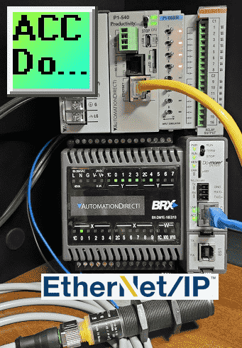
We will now utilize Ethernet/IP to connect a BRX Do-More PLC as remote IO on a Productivity system. The productivity series of controllers can use explicit and implicit messaging techniques of EtherNet/IP to optimize data exchanges across the network.
Explicit messaging means that the data messages that are transmitted will contain everything needed in order to respond or decode the message. It is a normal client/server relationship with instructions explicitly spelled out in the data messages. This communication happens at times that the Client requests the information.
Implicit messaging means the data messages are streamlined. The device is configured ahead of time to know what to do with the data. This is used for time-critical messages and it functions as a typical scanner/adapter relationship. Implicit messaging is real-time. It has the ability to copy data with minimal additional information because both ends already know exactly what each bit and byte.
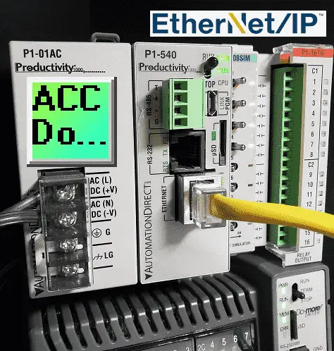
A BRX Do-More PLC will be set up as remote distributed inputs and outputs for our Productivity 1000 controller. Implicit Ethernet IP will be set up. The Do-More will be the Ethernet IP adapter and the Productivity will be the Ethernet IP scanner. Let’s get started.
Previously in this Productivity 1000 series PLC, we have discussed:
Productivity Suite Simulator – Video
System Hardware – Video
Installing the Software – Video
Establishing Communication – Video
First Program – Video
Documenting the Program – Video
Monitoring and Testing the Program – Video
Online Editing and Debug Mode – Video
Numbering Systems and Tag Database – Video
Contact and Coil Instructions – Video
Timer Instructions – Video
Counter Instructions – Video
Math Instructions – Video
Data Handling Instructions Part 1 – Video
Data Handling Instructions Part 2 – Video
Array Functions Part 1 – Video
Array Functions Part 2 – Video
Array Functions Part 3 – Video
Program Control – Video
Drum Sequencer Instructions – Video
Data Logger – Video
Web Server – Video
Modbus RTU Serial Communication – Video
Modbus TCP Ethernet Communication – Video
Firmware Update – Video
AdvancedHMI Modbus TCP Ethernet Communication – Video
Email and Text Communication – Video
PID Instruction – Video
PID Ramp Soak Instruction – Video
Modbus ASCII Protocol – Video
Stride Field Remote IO Modules Modbus TCP Ethernet
– Unboxing SIO MB12CDR and SIO MB04ADS Video
– Powering and Configuring Video
Productivity 1000 PLC to Stride Field IO Modbus TCP – Video
Modbus RTU TCP Remote IO Controller BX-MBIO
– BX-MBIO Hardware Video
– BX-MBIO Powering and Configuring Video
Productivity 1000 PLC to Modbus TCP RTU Remote IO Controller BX-MBIO – Video
Click EtherNet/IP Remote I/O – Video
Our entire P1000 series can be found here.
The programming software and manuals can be downloaded from the Automation Direct website free of charge.
BRX Do-More Ethernet/IP Server Adapter Setup
System Configuration
The BRX Do-More supports on top of the CIP (Common Industrial Protocol) layer supports IO Messaging (also called Class 1 Implicit). We will be using IO messaging for our remote application to the productivity. The adapter (server) is set up the same way for both Explicit and Implicit methods of Ethernet/IP.
Note: See the help file for the latest information on EtherNet/IP
In the Do-More Designer Programming Software, call up the system configuration menu. This is done by selecting the main menu | PLC | System Configuration…
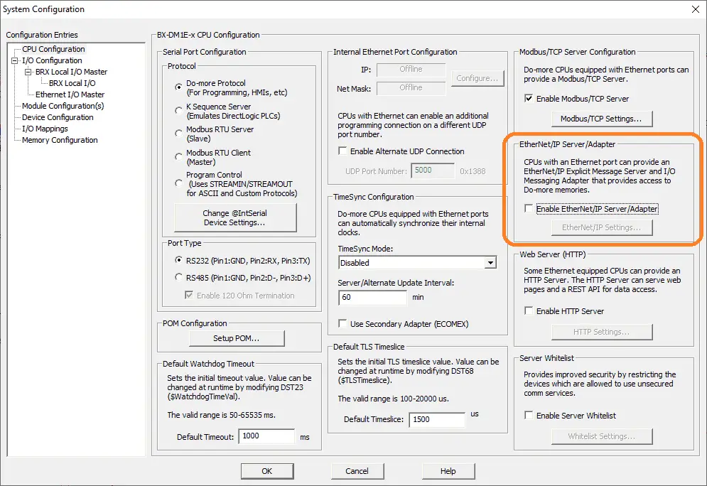
You can also select system configuration under the tools option in the project browser. This will call up the system configuration window.
The EtherNet/IP Server/Adapter settings must be enabled by selecting this option.
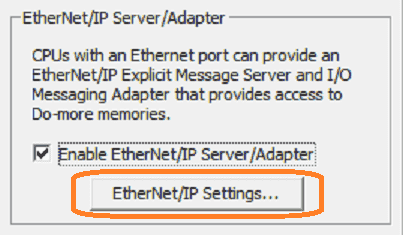
Once the enabled is checked, select the EtherNet/IP Settings… button.
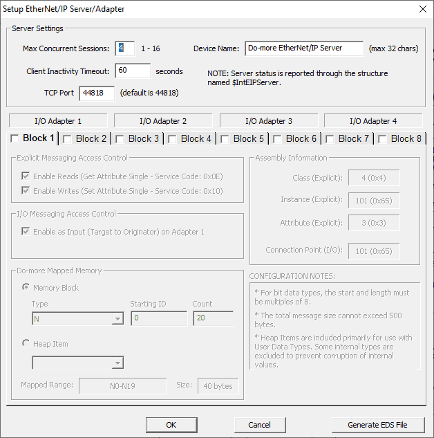
The setup EtherNet/IP Server/Adapter window will now be displayed.
Server Settings are selections that control how the EtherNet/IP Server handles connections from Explicit Message clients and Implicit Scanners :
Maximum Concurrent Sessions (1 – 16) value specifies how many simultaneous connections from Explicit Message Clients and/or Implicit Scanners the EtherNet/IP Server device driver can handle. Establishing an EtherNet/IP session requires processing time which will inevitably impact the scan time. If there are more EtherNet/IP Clients requesting connections than there are concurrent sessions available, part of this processing includes shutting down the oldest session so that anew session can be opened. The need to forcibly close sessions so that new ones can be opened can be minimized by setting this value to the maximum number of individual EtherNet/IP Clients that will be connecting to this PLC at any given time. This can be any constant value between 1 and 16.
Client Inactivity Timeout (seconds) specifies how much time (in seconds) to wait before closing the connection for an EtherNet/IP Client that has stopped communicating. This can be any constant value between 0 and 65535.
TCP Port Number (44818 is the default) specifies which TCP port number the EtherNet/IP Server will accept connections on. The default value of 44818. This is the industry standard, and value will rarely need to be changed. This can be any constant value between 0 and 65535.
Device Name will be returned in requests for the Identity Class, it can be up to 32 characters in length.
I/O Adapters
There are 4 available I/O Adapters. Each of the 4 I/O Adapters consumes two of the 8 available blocks. The first block for each I/O Adapter is the Input (Target -> Originator), the second block is the Output (Originator to Target).
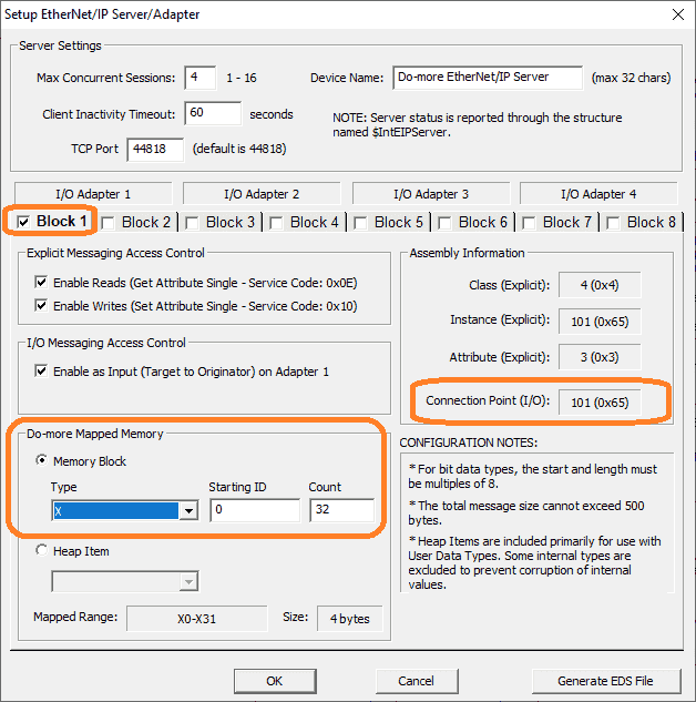
Select Block 1. This is part of I/O Adapter 1. Several options on the block get selected automatically.
I/O Messaging Access Control options define how the selected blocks can be accessed by an Implicit Scanner:
Enable as Input (Target to Originator) on Adapter x will allow read access to this block by Implicit Scanners.
Do-more Mapped Memory
We will specify our physical inputs on the BRX Do-More. X0 to X32.
Our connection point I/O is set for 101. This will now be related to the memory that we have just mapped. Select Block 2.
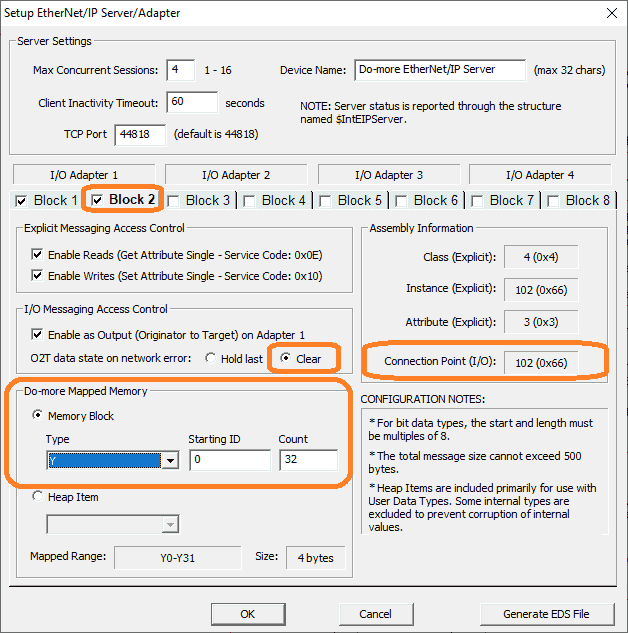
This is the output of I/O Adapter 1. Several options on the block get selected automatically.
I/O Messaging Access Control
Enable as Output (Originator to Target) on Adapter x will allow writing access to this block by Implicit Scanners.
If the I/O Adapter is enabled as an Output, O2T data state on network error determines the state of the contents of the block if the Implicit Scanner loses its network connection to this adapter:
•Hold last will leave the contents of the data block or heap item untouched.
•Clear will set all of the contents of the data block or the fields of the heap item to 0. Select clear because we want the outputs to clear if a network error occurs.
Do-more Mapped Memory
We will specify our physical outputs on the BRX Do-More. Y0 to Y32.
Our connection point I/O is set for 102. This will now be related to the memory that we have just mapped. Select Block 3.
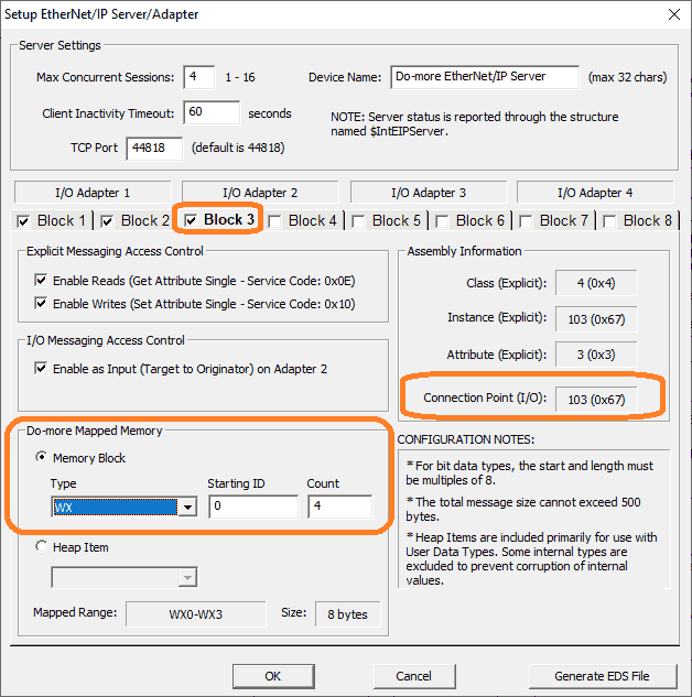
This is the input of I/O Adapter 2. We will specify our analog input area WX0 to WX4. Two bytes are used for each memory location. (8 Bytes Total) The connection point I/O is 103. Select Block 4.
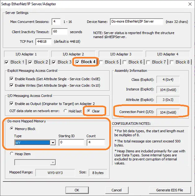
This is the output of I/O Adapter 2. We will clear the outputs when a network error occurs. The analog output area will be WY0 to WY4.
Select OK.
We have now completed the BRX Do-More EtherNet/IP Server Adapter.
BRX Do-More Program
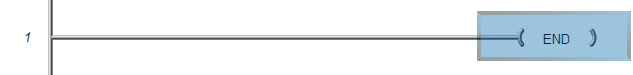
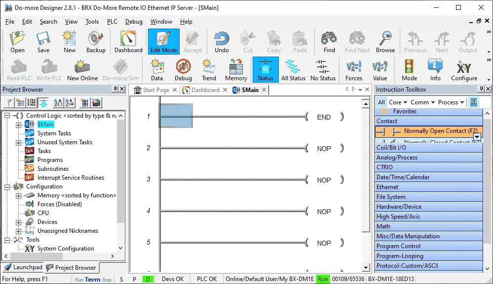
We will place an end statement in our ladder logic program. This will ensure that no errors will be generated. The BRX will only be used for remote inputs and outputs only.
Connect and send the program and configuration to the BRX Do-More PLC. Place the PLC in run mode.
We will now check the IP address configuration of the Do-More controller.
Call up the system configuration once again.
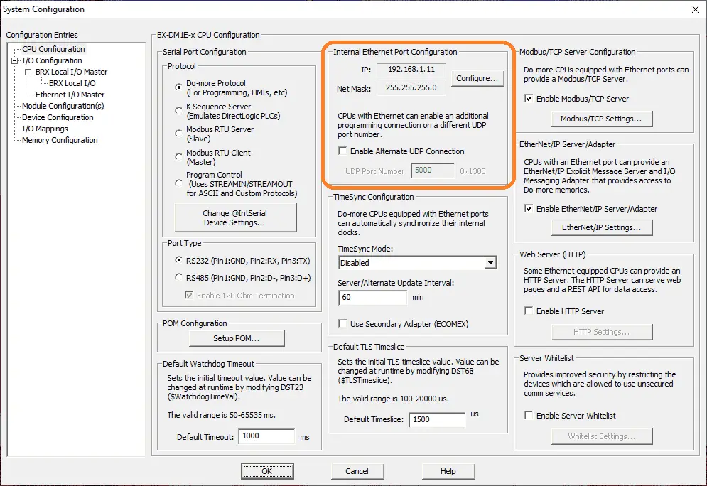
Under the CPU configuration on the left-hand side, you will see the Internal Ethernet Port Configuration information. Select Configure…
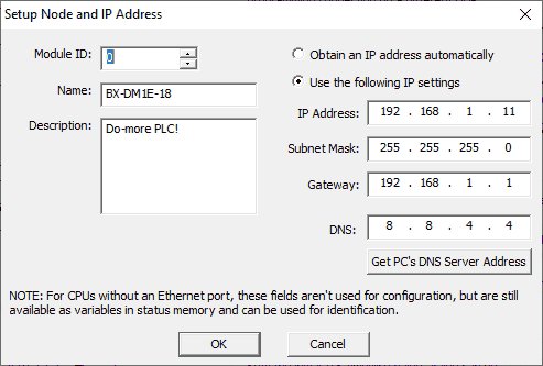
Ensure that we are using a static IP address by selecting the “Use the following IP settings” option. This will be needed for the EtherNet/IP scanner to know where the adapter is located. Select OK to close the configuration window and then OK on the system configuration window.
BRX Do-More System Information (Scan Time)
The system information window will display the scan time of the PLC under the general information tab.
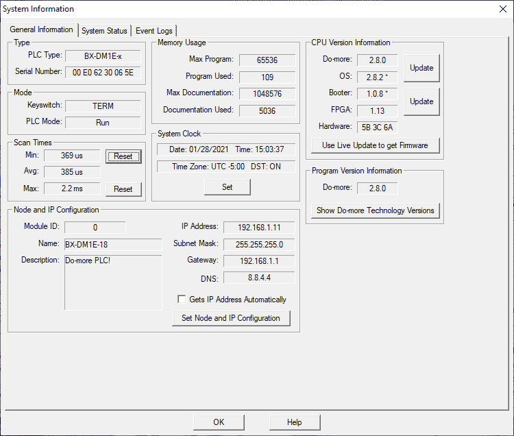
Select main menu | PLC | System Information… Alternatively, you can also select System Info under the tools heading in the project browser.
We will be communicating to our remote I/O every 10 milliseconds so we needed to ensure that the scan time is below this value. In our case, the maximum scan time was 2.2 milliseconds with an average scan time of 0.385 milliseconds. This will be fine for our EtherNet/IP network.
Productivity EtherNet/IP Client Setup
Select “hardware configure” from the main menu | Setup.
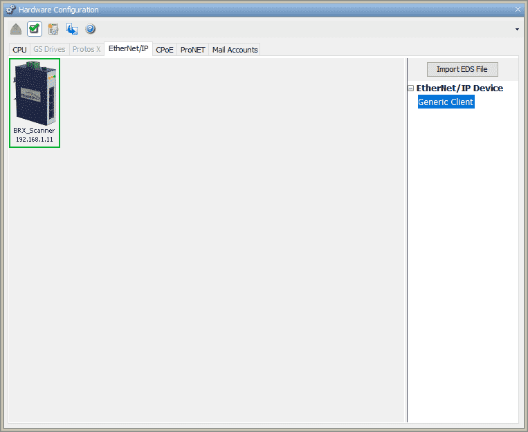
Select the Ethernet IP tab of the hardware configuration window.
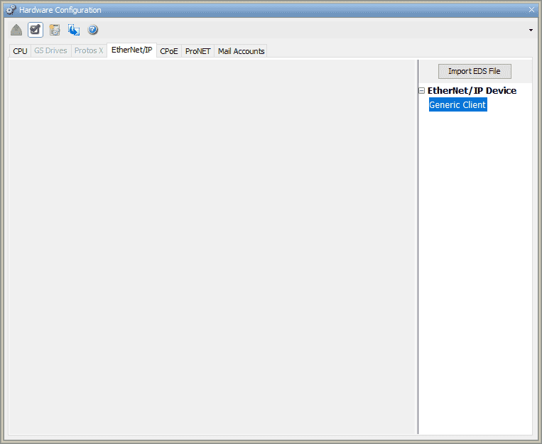
This will then display the Ethernet/IP clients configured.
To add a client, double click on the Generic Client under the EtherNet/IP Device.
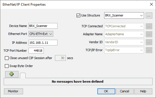
You can also left-click and drag the generic client onto the blank page. This will display the EtherNet/IP Client properties window.
Select use structure and give it a name. BRX_Scanner is used for the structure and device name. Type in the address of the BRX Do-More Ethernet/IP Adapter from above. We will leave all of the other settings as their default. Click the green plus icon.
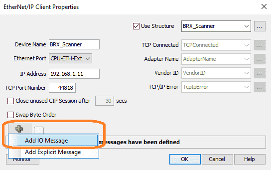
Select add IO Message. This sets implicit messaging for our productivity Ethernet IP scanner.
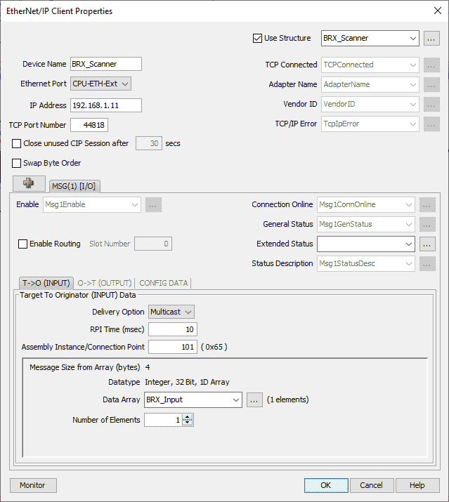
MSG(1) I/O tab will now be displayed. Three tabs will now be available. The first tab ‘Target to Originator (INPUT) Data’ is automatically selected.
We will leave all fields as their default and fill in the following:
RPI (Request Package Interval) Time (msec) = 10
Assembly Instance/Connection Point = 101 – This is the same as the inputs connection point set in the BRX Do-More above.
Data Array will be called BRX_Input and the number of elements will be 1.
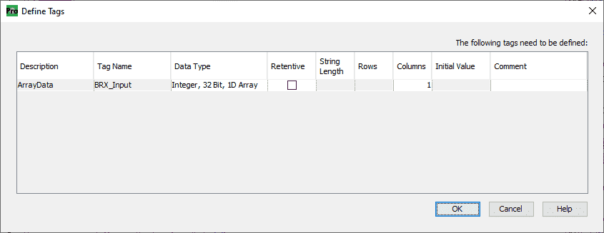
Define the tag as Integer, 32 Bit, 1D Array with 1 column. Select OK. This will match the 4 bytes of information that the connection point is looking to obtain.
Select the ‘Originator to Target (OUTPUT) Data’ tab.
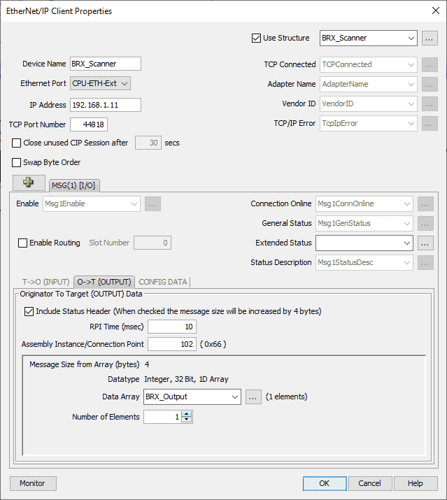
We will leave all as the default except for the following:
RPI Time (msec) = 10
Assembly Instance/Connection Point = 102 – This is the same as the output connection points set in the BRX Do-More above.
Data Array will be called BRX_Output and the number of elements will be 1.
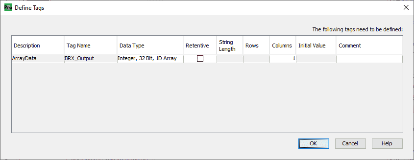
Define the tag as Integer, 32 Bit, 1D Array with 1 column. Select OK. This will match the 4 bytes of information that the connection point is looking to obtain.
Click the OK button.
Select the ‘CONFIG DATA’ tab.
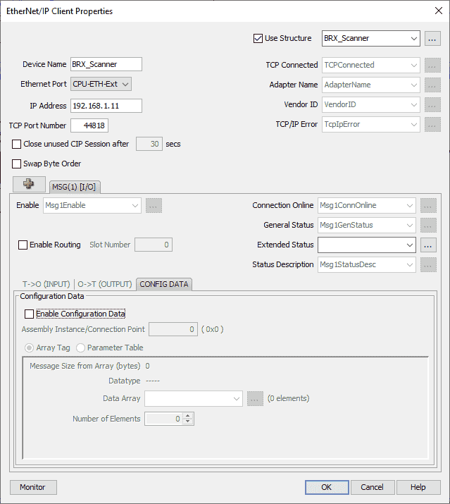
Ensure that the enable configuration data is not selected.
We will now program in the analog input and output information. Select the green plus icon again and select ‘Add IO Message’.
Select MSG(2) IO tab.
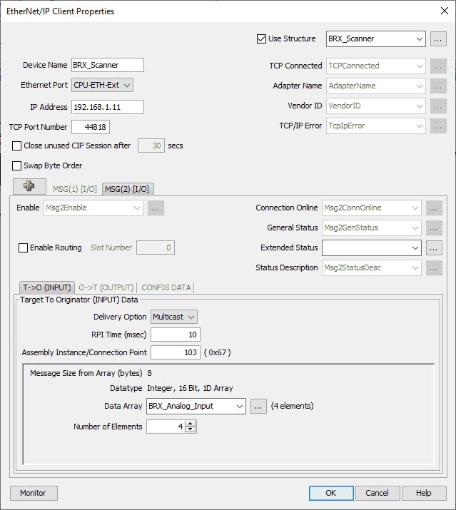
‘Target to Originator (INPUT) Data’ tab will be displayed.
We will leave all fields as their default and fill in the following:
RPI (Request Package Interval) Time (msec) = 10
Assembly Instance/Connection Point = 103 – This is the same as the Analog Input connection point set in the BRX Do-More above.
Data Array will be called BRX_Analog_Input and the number of elements will be 4.
Define the tag as Integer, 16 Bit, 1D Array with 4 columns. Select OK. This will match the 8 bytes of information that the connection point is looking to obtain.
Select the ‘Originator to Target (OUTPUT) Data’ tab.
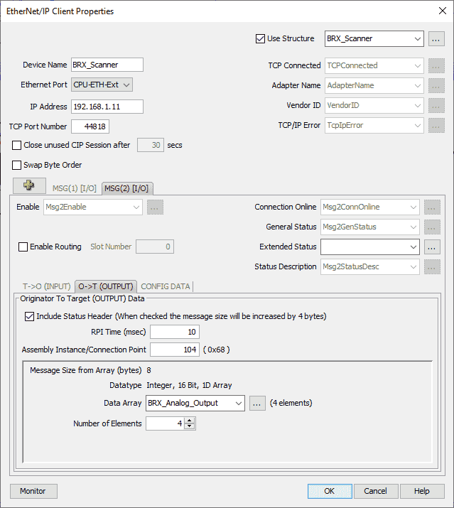
We will leave all as the default except for the following:
RPI Time (msec) = 10
Assembly Instance/Connection Point = 104 – This is the same as the analog output connection points set in the BRX Do-More above.
Data Array will be called BRX_Analog_Output and the number of elements will be 4.
Define the tag as Integer, 16 Bit, 1D Array with 4 columns. Select OK. This will match the 8 bytes of information that the connection point is looking to obtain.
Select the ‘CONFIG DATA’ tab.
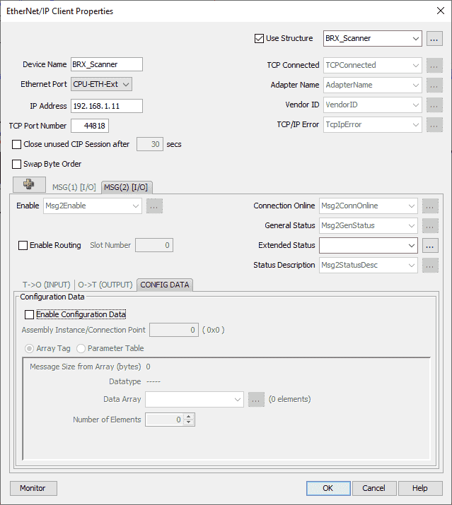
Ensure that the enable configuration data is not selected.
Select the Monitor button on the bottom left side of the window.
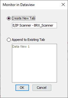
This will add a new tab in the Dataview for us to monitor the Ethernet/IP Scanner in the Productivity Suite software. Select OK.
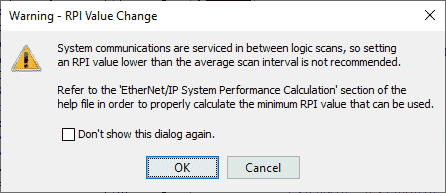
A warning about the request package interval will be displayed. This is to ensure that the value is not lower than the average scan time. Select OK.
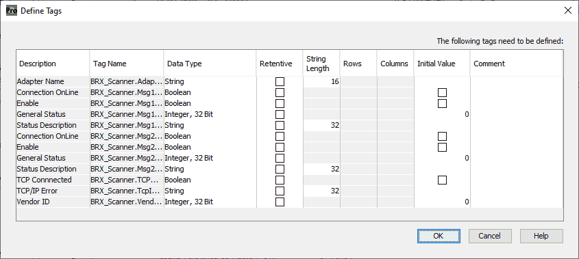
We can now define the tags used with our BRX Do-More scanner. Leave everything as their default and select OK.
Our productivity Ethernet/IP click scanner has now been programmed.
Productivity BRX Do-More Remote IO Program
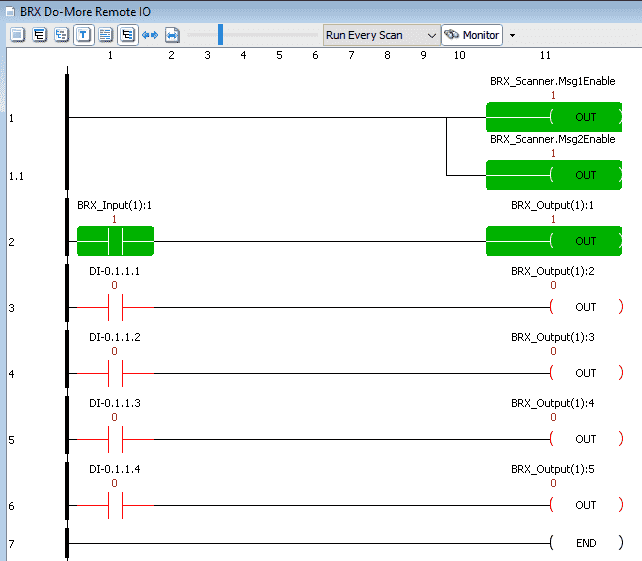
Our simple ladder logic program will ensure that the BRX Do-More scanner message 1 and 2 are enabled.
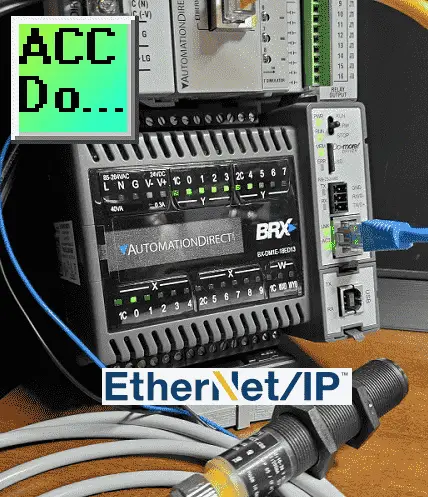
We will also add the first input (X0) on the BRX Do-More will turn on the first output (Y0) of the BRX Do-more. The input in our case is hooked up to a proximity sensor. The first four inputs on the productivity simulator card will control the next four outputs on our BRX Do-More controller. Save the program.
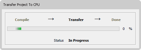
Transfer the program to the controller.
While we are online to the productivity CPU, check the scan time.
The ‘get scan time’ window can be displayed by selecting it from the main menu | CPU| Get CPU Scan Time.
Since the remote IO will update every 10 milliseconds, we are well within our local scan times on each controller.
Watch the video below to see the BRX Do-More PLC act as remote IO to the Productivity 1000 PAC controller.
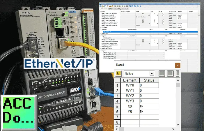
Monitoring the Productivity BRX Do-More EthernetIP Remote IO
Call up the data view monitoring in the productivity suite software.
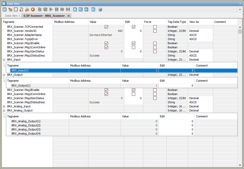
The E/IP scanner BRX Scanner tab was created when we selected the monitor above. We can now test the communications.
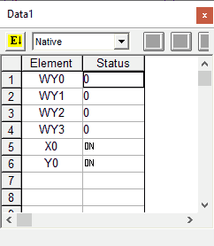
Call up the data view monitoring in the Do-More designer programming software.
We can view the IO in the BRX Do-More through this software.
See the video below using the Click PLC as the Productivity remote inputs and outputs.
Download the Productivity 1000 and BRX Do-More PLC programs here.
Productivity 1000 Series PLC from Automation Direct
Overview Link (Additional Information on the Unit)
Configuration (Configure and purchase a system – BOM)
User Manual and Inserts (Installation and Setup Guides)
Productivity Suite Programming Software (Free Download Link)
This software contains all of the instruction sets, and help files for the Productivity Series.
EtherNet/IP Learning Links:
ODVA – EtherNet/IP Overview
Productivity Series – EtherNet/IP – How to Setup an I/O (Implicit) Scanner – Video
Ethernet/IP: 5 Things You Must Know – Video
Watch on YouTube: Productivity BRX Do-More EtherNet/IP Remote IO
If you have any questions or need further information please contact me.
Thank you,
Garry
If you’re like most of my readers, you’re committed to learning about technology. Numbering systems used in PLC’s are not difficult to learn and understand. We will walk through the numbering systems used in PLCs. This includes Bits, Decimal, Hexadecimal, ASCII and Floating Point.
To get this free article, subscribe to my free email newsletter.
Use the information to inform other people how numbering systems work. Sign up now.

The ‘Robust Data Logging for Free’ eBook is also available as a free download. The link is included when you subscribe to ACC Automation.