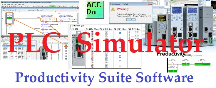
The productivity suite software now contains a plc simulator. The software is a free download and is available from automation direct. This software will now allow you to test or troubleshoot your program without the physical hardware present. The entire family of controllers can use the simulator. P1000, P2000, and P3000 emulation can happen on the following parts of the productivity series hardware:
– P1000 CPU’s and local I/O stack, P2000 and P3000 CPU’s and local bases
– All basic I/O modules, both analog and digital
– Modbus TCP Server/Client connections on external Ethernet port
The simulation mode is available on the Productivity Suite version 3.8.x.x or higher. We will be discussing the PAC (Programmable Automation Controller) PLC Simulator. Testing this simulator will be done using our first program (Start-Stop Circuit) and the PID instruction in our Productivity 1000 series. We will also be connecting to physical hardware after using our simulator to test the program. Let’s get started.
Previously in this Productivity 1000 series PLC, we have discussed:
System Hardware – Video
Installing the Software – Video
Establishing Communication – Video
First Program – Video
Documenting the Program – Video
Monitoring and Testing the Program – Video
Online Editing and Debug Mode – Video
Numbering Systems and Tag Database – Video
Contact and Coil Instructions – Video
Timer Instructions – Video
Counter Instructions – Video
Math Instructions – Video
Data Handling Instructions Part 1 – Video
Data Handling Instructions Part 2 – Video
Array Functions Part 1 – Video
Array Functions Part 2 – Video
Array Functions Part 3 – Video
Program Control – Video
Drum Sequencer Instructions – Video
Data Logger – Video
Web Server – Video
Modbus RTU Serial Communication – Video
Modbus TCP Ethernet Communication – Video
Firmware Update – Video
AdvancedHMI Modbus TCP Ethernet Communication – Video
Email and Text Communication – Video
PID Instruction – Video
PID Ramp Soak Instruction – Video
Modbus ASCII Protocol – Video
Stride Field Remote IO Modules Modbus TCP Ethernet
– Unboxing SIO MB12CDR and SIO MB04ADS Video
– Powering and Configuring Video
Productivity 1000 PLC to Stride Field IO Modbus TCP – Video
Modbus RTU TCP Remote IO Controller BX-MBIO
– BX-MBIO Hardware Video
– BX-MBIO Powering and Configuring Video
Productivity 1000 PLC to Modbus TCP RTU Remote IO Controller BX-MBIO – Video
Our entire P1000 series can be found here.
The programming software and manuals can be downloaded from the Automation Direct website free of charge.
Watch the video below to see Productivity PAC PLC Simulator in action controlling our first program.
Productivity Suite – PLC Programming Software
A PLC simulator has now been added to the productivity suite software for easy logic verification/testing without hardware. Version 3.8.xx or newer is required. We are using version 3.8.0.14 for our samples.
Productivity Suite Download Here
Capability:
• Analog or Discrete I/O simulation
• Data View monitoring
• Modbus TCP/IP (Computer Ethernet port – Client (Master) or Server (Slave) – Connect an HMI / Data Logger etc.
• Ignores unsupported instructions
Current Limitations:
• No intelligent modules
• No external Ethernet port for HMI, GUI, Ethernet/IP, etc (except noted above)
• No remote Ethernet port to Remote Slaves, GS Drives, ProtosX, etc
• RS232/485 ports
• ProNet
• LCD / UIM displays
• LCD / UIM keyboards
• Removable memory devices
• Communication Instructions are not supported: AIN/AOUT, ACLR, GSR/GSW, CPE/CPI/CPO, EMAL, DWX, VMW, EMSG
• Motion Instructions are not supported: HOME, SPOS, PLS, VMOV, REG, WHSO, SMOV
• PID Instruction is not supported
Current Restrictions:
• Forceable outputs will not work in the simulator in this version 3.8.0.14
• The simulator does time out after 2 hours. The help file will get updated with this note on the next release.
P1000 PLC Program Simulator First Sample
We will now create a new project based on the first program that we did on the P1000 series. Download and install the productivity suite software from the link above or below.
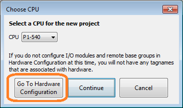
We will start a new project so we can simulate the program. Choose the P1-540 CPU and then select go to hardware configuration.
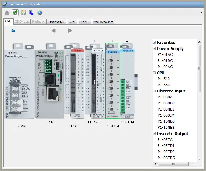
Configure the hardware in the hardware configuration window. This will reflect the same hardware that we physically would like to program. In our case, we have added a power supply, relay output, combination 24DC input/relay output, simulator input, and a thermocouple input card.
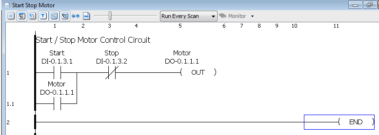
We will now program our logic. This will be our start stop motor control circuit.
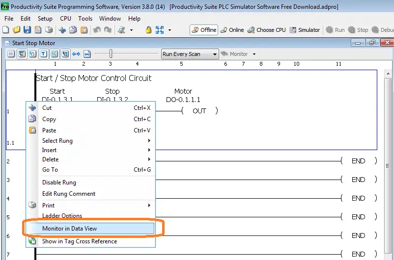
Right-click on the rung and select monitor in the data view.
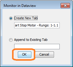
Leave the selection as create a new tab and select OK. This will set up our data view so we can view our inputs and outputs easily.
Start the Simulator
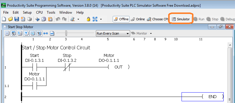
Select the simulator icon on the main menu display. You can also select the main menu | CPU | Simulator.
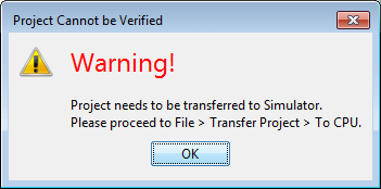
A warning message is displayed. This indicates that the program will need to be transferred from the computer to the plc simulator. Think of the simulator as separate hardware that you cannot see. Select OK.
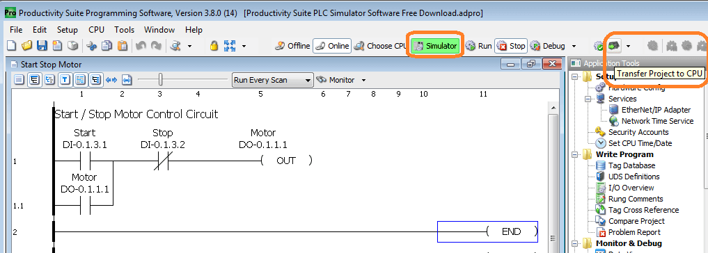
You can see now that we are online with the PLC simulator. Select the transfer project to CPU icon or use the main menu | File | Transfer Project | to CPU.
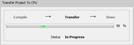
Our ladder logic program will now be transferred to the plc simulator.
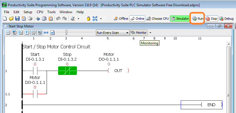
Select monitor on our circuit start stops motor window. This will show the status of the inputs and outputs. Now select the run icon or use the main menu | CPU | Run.
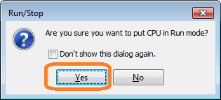
A confirmation window will appear. Answer yes to put the plc simulator in run mode.
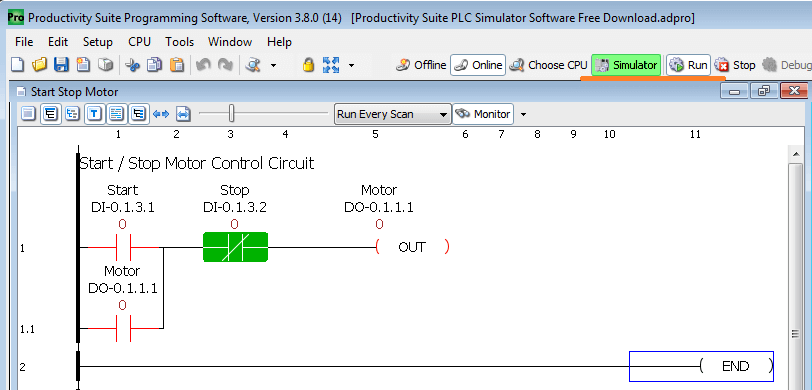
Our ladder logic program is now running on the simulator. We will now control the inputs and outputs through the data view.
Controlling Simulator Inputs and Outputs
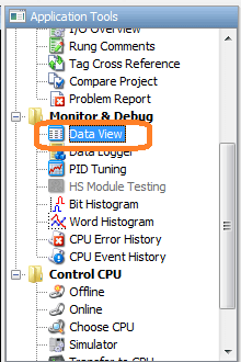
Select data view in the application tools under the monitor and debug. You can also call this up using the main menu | Tools | Data View or use the shortcut key combination Ctrl + Shift + F3.
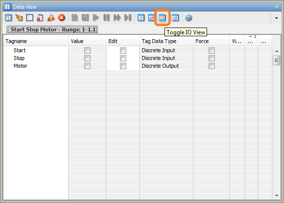
Select the toggle IO view icon from the data view window.
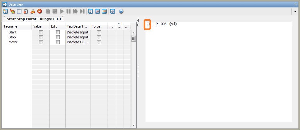
Select the + on the IO view part of the data view window.

This will now show you the graphical representation of the PLC hardware in the simulator in the order the modules are attached.
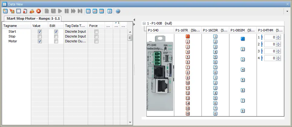
Clicking on the first input of the simulator 8 point input card will then turn on the first output of the relay card.
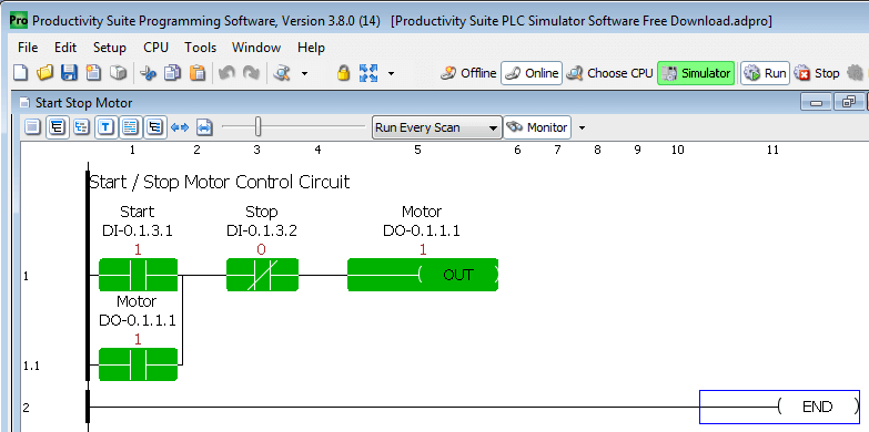
This is shown on the ladder logic diagram.
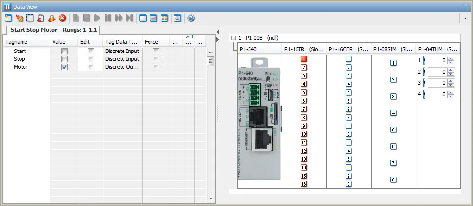
Click on the first input of the simulator 8 point input card again will turn the input off.
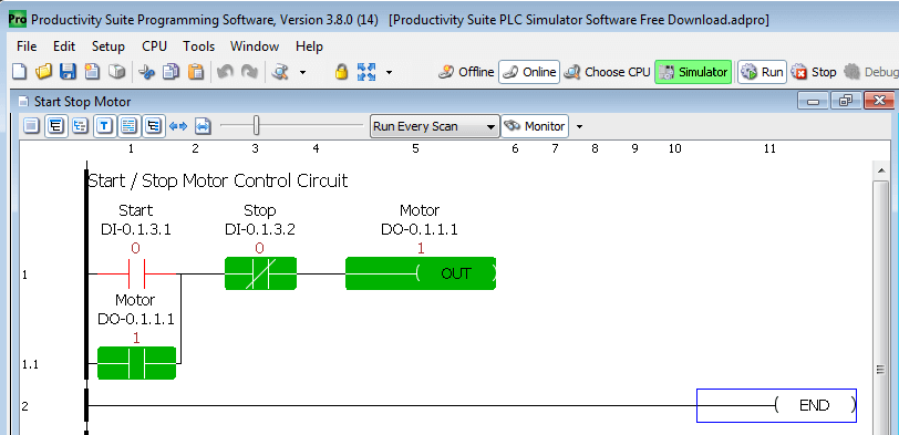
Our ladder logic will show that the start signal is now off. The motor output continues to be on because of the sealing contact for the start.
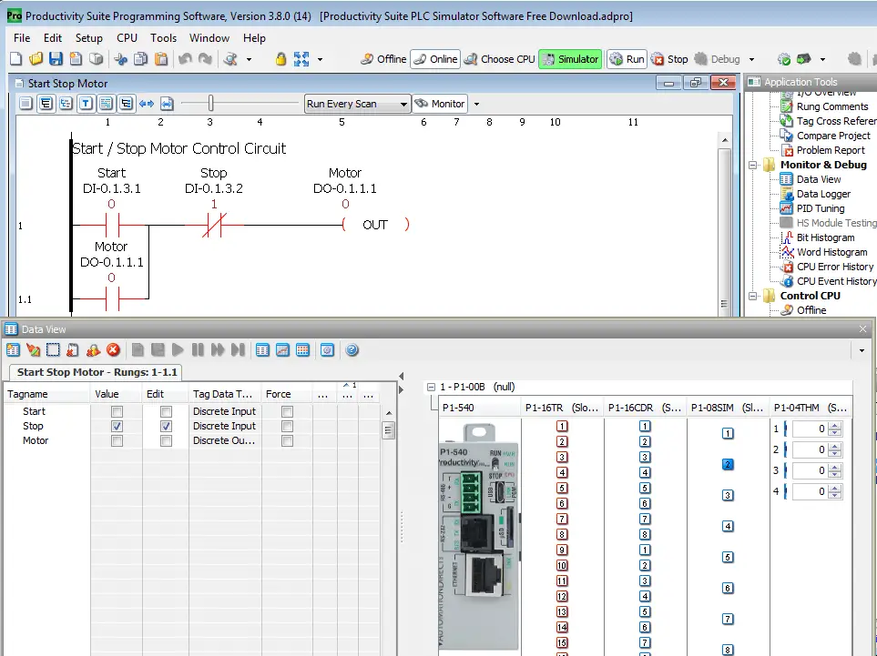
Turning on input 2 of the simulator input will stop the motor from operating according to our ladder logic.
The Productivity Suite simulator allows you can verify the effects of code changes before implementation, replicate fault conditions to test code stability, or trying out new programming techniques/methods for greater efficiency. This can jump-start your project development on the front end and reduce unexpected errors with systems that are already live.
P1000 PLC Program Simulator PID Sample
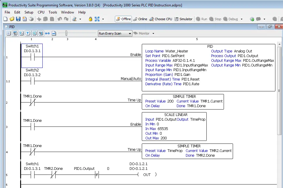
We will now call up the PID Instruction sample program that we looked at in the P1000 series training.
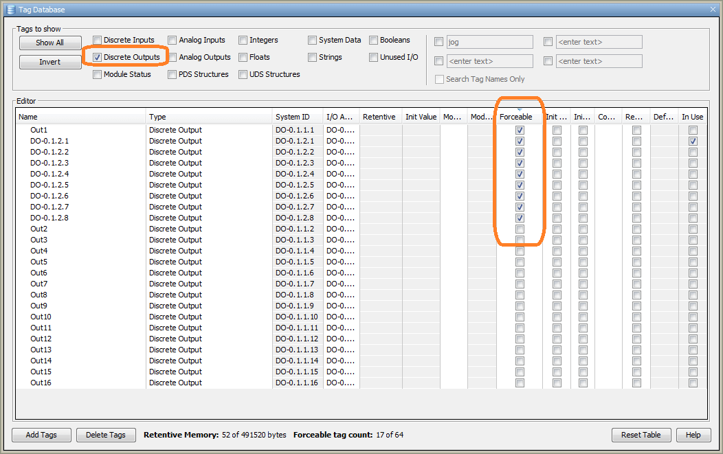
Call up the tag database window by selecting it in the application tools under write program. You can also use the main menu | Edit | Tag Database.
Select the discrete outputs and then sort by forceable. Click on each of these forceable bits to turn them off. (Make them not forceable.)
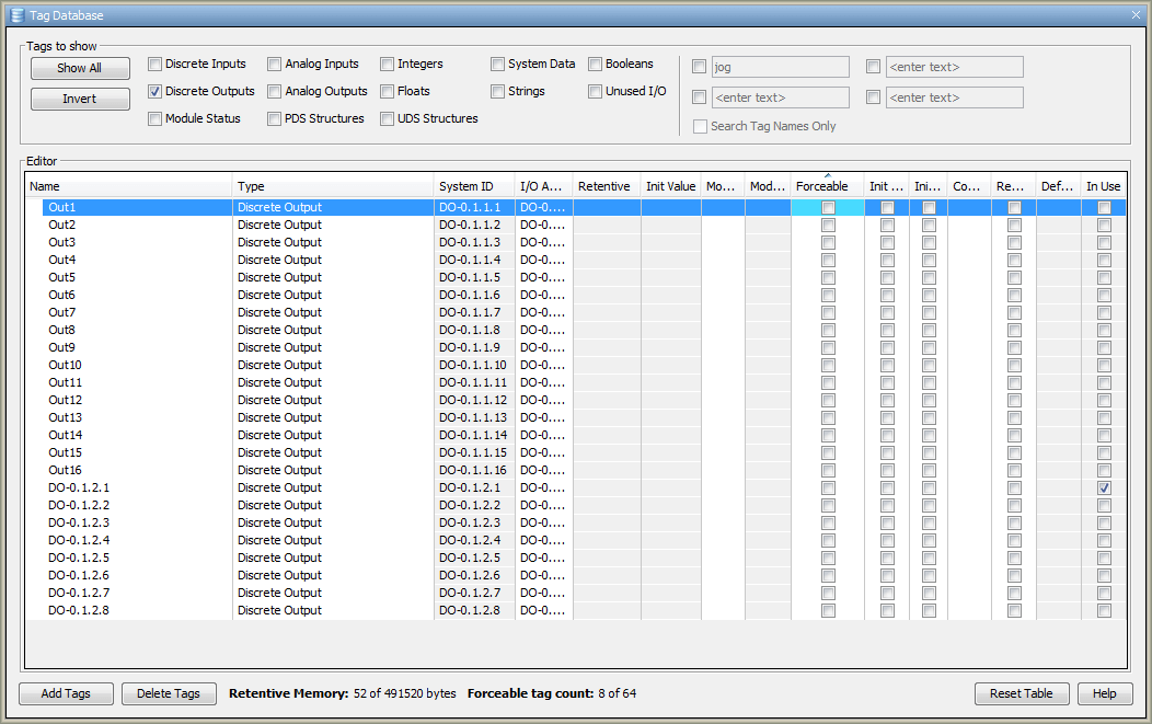
Forceable outputs will not work in the simulator with this version. (3.8.0.14)
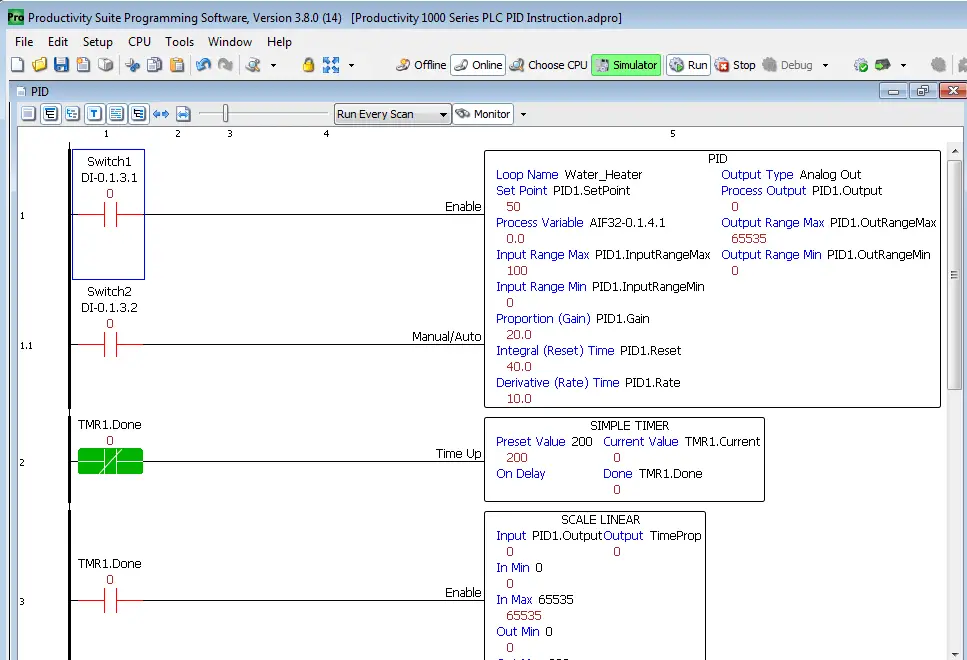
Select the simulator, transfer the program to the CPU, and then place the simulator into run mode.

Call up the data view window and toggle the IO view.
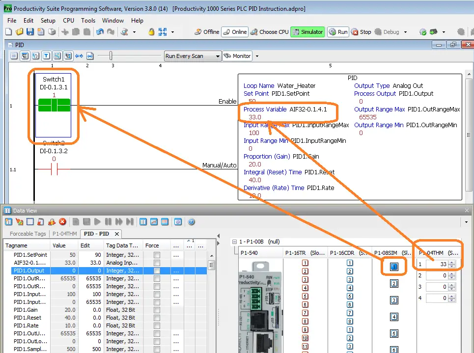
You will see that the thermocouple input can be changed and it will show up as the process variable in the PID instruction. The first input of our simulator input card will toggle the switch 1 input on/off.
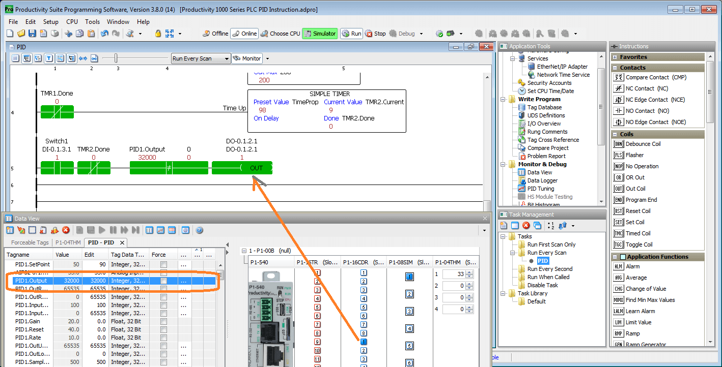
Even though PID is not supported in the simulator, we can change the PID output variable to mimic its use in our program. Setting it in the data view to half of the PID output maximum value will turn our output on and off at about 50% of the cycle time.
Select the offline icon on the main menu. This will disconnect the simulator.
Connecting to Physical Hardware after the Simulator
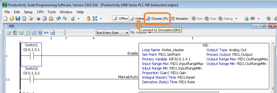
Once we disconnect from the simulator, the online icon will remember the last connection made with the program. In our case, this is the simulator (SIM). In order to now connect to the physical hardware, we must select choose CPU from the main menu icons.
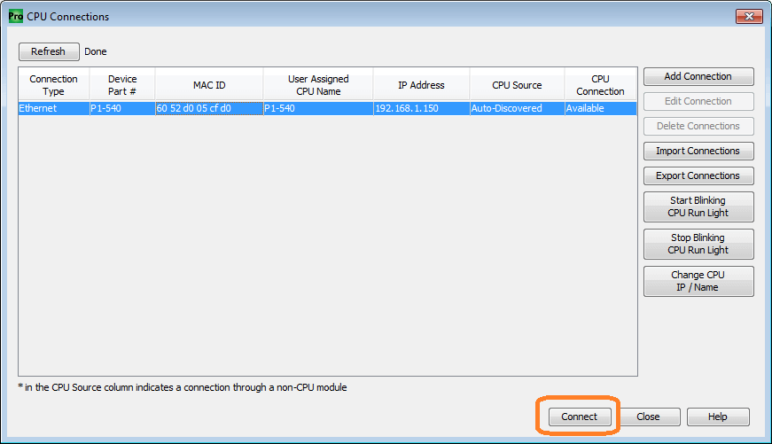
Ensure that the physical PLC is plugged in and the Ethernet cable is connected. The PLC will be displayed on the available list for CPU connections.
Select the plc and select the connect button.

Since the program in the PLC is different than the one in the software this project differences window will be displayed. Select no, use pc project.

We can now download the program into the hardware.
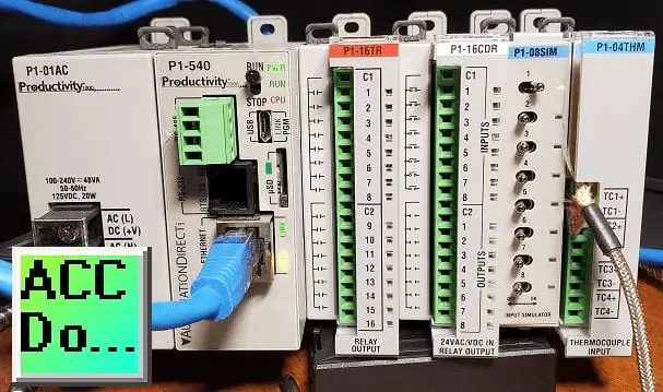
There is no better way to get a head start on project development than building code ahead of time with the assistance of a project simulator. Now you can start your logic early and verify its operation even before the hardware has arrived! This tool will come in handy not only with new builds but also when maintaining existing systems.
See the video below on using the productivity suite plc simulator.
Download the Productivity Suite Sample PLC programs here.
Productivity 1000 Series PLC from Automation Direct
Overview Link (Additional Information on the Unit)
Configuration (Configure and purchase a system – BOM)
User Manual and Inserts (Installation and Setup Guides)
Productivity Suite Programming Software (Free Download Link)
This software contains all of the instruction sets and help files for the Productivity Series.
Watch on YouTube: Productivity Suite PLC Simulator Software Free Download
If you have any questions or need further information please contact me.
Thank you,
Garry
If you’re like most of my readers, you’re committed to learning about technology. Numbering systems used in PLC’s are not difficult to learn and understand. We will walk through the numbering systems used in PLCs. This includes Bits, Decimal, Hexadecimal, ASCII and Floating Point.
To get this free article, subscribe to my free email newsletter.
Use the information to inform other people how numbering systems work. Sign up now.
The ‘Robust Data Logging for Free’ eBook is also available as a free download. The link is included when you subscribe to ACC Automation.

