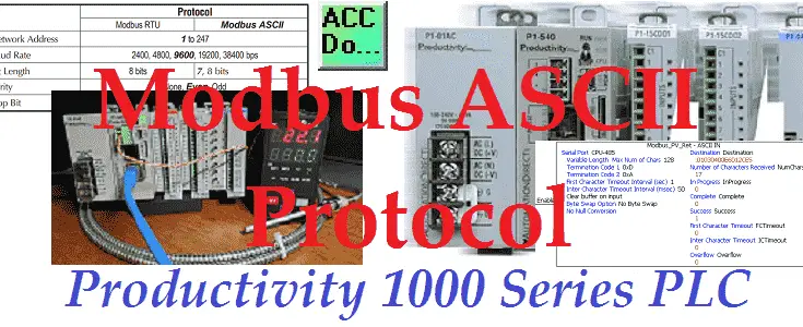
We will not look at the productivity 1000 plc modbus ascii protocol to the Solo process temperature controller. This will be done in ladder logic on our productivity 1000 PLC. Modbus ASCII is a communication method used for transmitting information over serial lines between electronic devices. The device requesting the information is called the Modbus Master (Client) and the devices supplying information are Modbus Slaves (Servers). This protocol was originally developed by Modicon systems.
Modbus protocol comes in basically three different types. Ethernet (Modbus TCP) or Serial (Modbus RTU or Modbus ASCII). Modbus TCP and Modbus RTU come as standard protocols in the productivity series of PLCs.
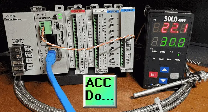
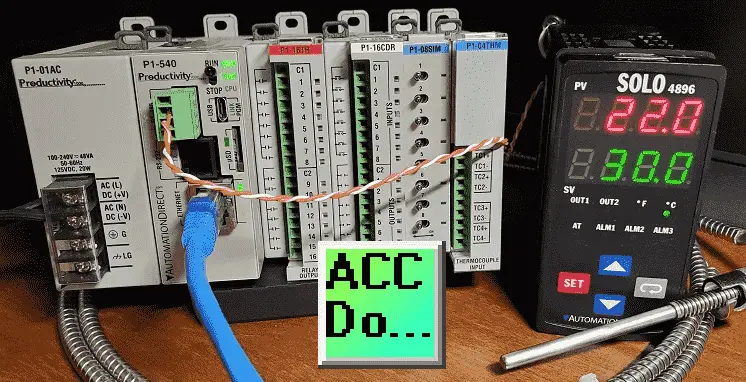
We will connect the Productivity 1000 PLC to a Solo process temperature controller. This will be done using the Modbus ASCII protocol over serial RS485 communication wire. (Media) The present and set values (PV / SV) will be read from the Solo controller and the set value will be written when required. Let’s get started.
Previously in this Productivity 1000 series PLC, we have discussed:
System Hardware – Video
Installing the Software – Video
Establishing Communication – Video
First Program – Video
Documenting the Program – Video
Monitoring and Testing the Program – Video
Online Editing and Debug Mode – Video
Numbering Systems and Tag Database – Video
Contact and Coil Instructions – Video
Timer Instructions – Video
Counter Instructions – Video
Math Instructions – Video
Data Handling Instructions Part 1 – Video
Data Handling Instructions Part 2 – Video
Array Functions Part 1 – Video
Array Functions Part 2 – Video
Array Functions Part 3 – Video
Program Control – Video
Drum Sequencer Instructions – Video
Data Logger – Video
Web Server – Video
Modbus RTU Serial Communication – Video
Modbus TCP Ethernet Communication – Video
Firmware Update – Video
AdvancedHMI Modbus TCP Ethernet Communication – Video
Email and Text Communication – Video
PID Instruction – Video
PID Ramp Soak Instruction – Video
Stride Field Remote IO Modules Modbus TCP Ethernet
– Unboxing SIO MB12CDR and SIO MB04ADS Video
– Powering and Configuring Video
Productivity 1000 PLC to Stride Field IO Modbus TCP – Video
Modbus RTU TCP Remote IO Controller BX-MBIO
– BX-MBIO Hardware Video
– BX-MBIO Powering and Configuring Video
Productivity 1000 PLC to Modbus TCP RTU Remote IO Controller BX-MBIO – Video
Our entire P1000 series can be found here.
The programming software and manuals can be downloaded from the Automation Direct website free of charge.
Watch the video below to see P1000 Productivity PLC implement the Modbus ASCII protocol to read and write to the Solo process temperature controller.
Solo Process Temperature Controller
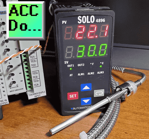
All Solo Standard Controllers are capable of Modbus communication.
The data and bit registers support the following Modbus function codes.
Data Registers
03: Read Holding Registers (maximum limit is read of eight registers)
06: Write Single Register
16: Write Multiple Registers (maximum limit is eight)
Bit Registers
01: Read Coils
02: Read Discrete Inputs (Both Function Code 1 & 2 read the same memory area.)
05: Write Single Coil (Write FF00H to set the coil or 0000H to reset the coil.)
The Modbus addresses for the Solo process temperature controller can be found in chapter 7 of the manual. See the link below.
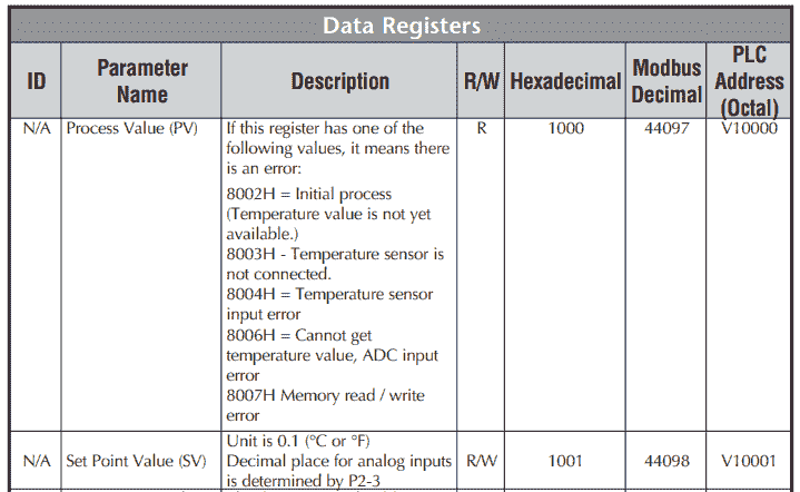
In our example, we will be reading the PV and SV values from the controller and write the SV when required.
Solo Process Temperature Controller Configuration
The first thing that we will do is set up the Solo Temperature Controller. Additional information can be found at the following link.
Wiring diagram:
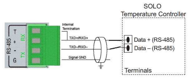
I have found the following connectors are great to test and connect if you are unsure of the communication pinout.
Just select a DB9, DB25, or DB15 connector depending on the number of pins of your serial port.
These connectors should be part of everyone’s toolbox. You never know when they will come in handy.
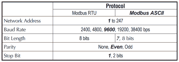
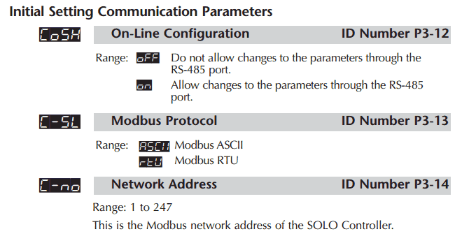
The solo process temperature controller needs to be set up before we can communicate with it. The default setting is ‘Off’ for the On-Line Configuration. Here is the way to change into the different modes in the Solo.
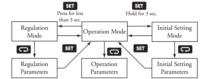
In the Initial Setting Mode we will change the online configuration to on and make the changes to the Modbus settings as follows: 19200 Baud, Even, 7 Data Bits, 1 Stop Bit, Modbus ASCII Format. We will leave the default unit number as 1.
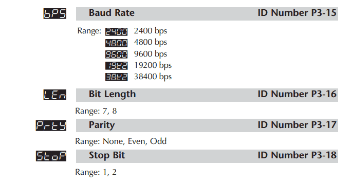
Our controller is now set to communicate.
Download the documentation and/or configuration and monitoring software at the following URL link:
Solo Process Temperature Controller Manual
Solo Software Download
Mobus ASCII Protocol Format
As the name states, ASCII (American Standard Code for Information Interchange) is used for the communication messages.
Modbus ASCII marks the start of each message with a colon character “: ” (hex 3A).
The end of each message is terminated with the carriage return and line feed characters (hex 0D and 0A).
Example:
Sent data from the master
:010310000002EA
: – Start of message
01 – Address (unit) number
03 – Function Code (read multiple registers)
1000 – Data – Starting address to read
0002 – Data – Number of registers to read
EA – LRC (Longitudinal Redundancy Check) error checking byte
Response data from the slave
:01030400DC012CEE
: – Start of message
01 – Address (unit) number
03 – Function Code (read multiple registers)
04 – Number of return registers in bytes
00DC – Data returned PV in Hexadecimal = 22.1 degrees C
012C – Data returned SV in Hexadecimal = 30.0 degree C
EE – LRC (Longitudinal Redundancy Check) error checking byte
The bytes that you see in sending and receiving information is represented by two ASCII characters. Each ASCII character is 8 bits long. This means that Modbus ASCII sends more information back and forth than Modbus RTU.
Note: Since the space between bytes is variable, transmission through modems is possible with Modbus ASCII.
Productivity 1000 PLC System Modbus Setup – Master
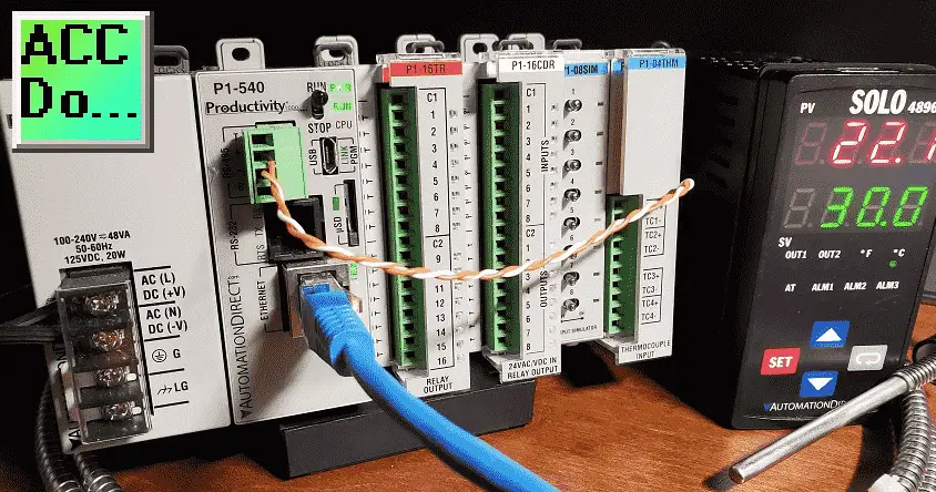
Our productivity plc will act as the Modbus master (Client). It will communicate to the Solo Process Temperature Controller which is a Modbus slave (Server).
Call up the Hardware Configuration window by using the main menu | Setup | Hardware Config.
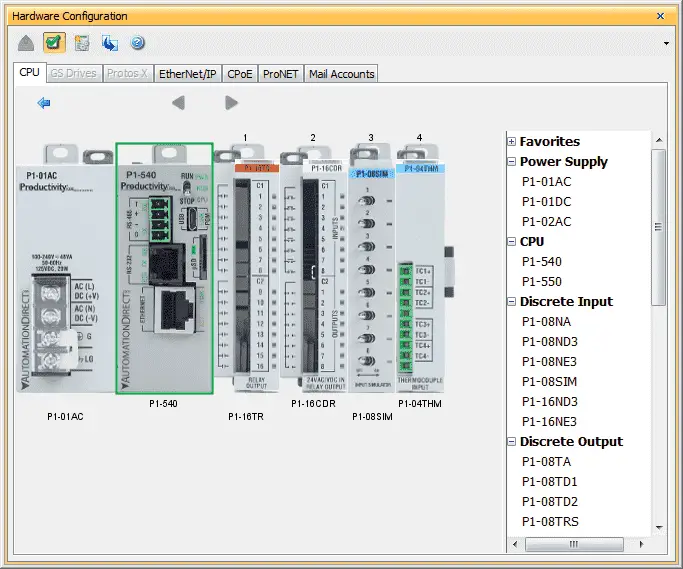
Double click on the CPU module to call up the P1-540 window.
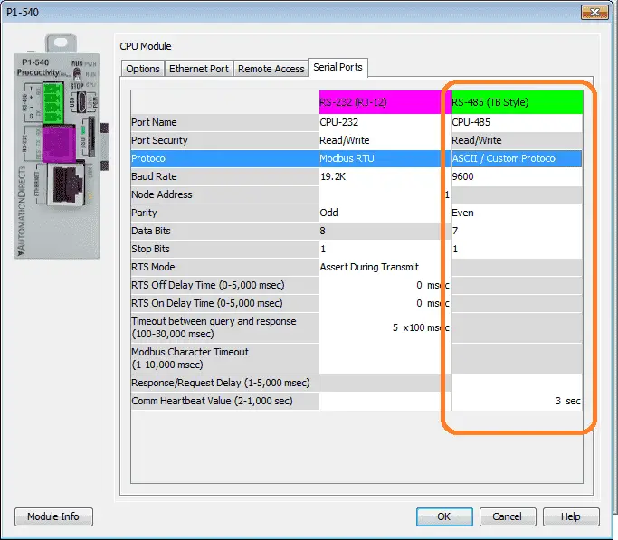
The options tab has the status bits and user tag names for the RS485 port that we will be using in our program. Select the Ethernet Port tab.
We will set the settings as indicated above under the RS-485 (Terminal Block – TB Style)
Select ASCII / Custom Protocol for the protocol selection. We will be creating Modbus ASCII. The port settings (baud rate, data bits, stop bits, parity, etc.) must match the settings on the Solo controller unit. Select OK. The P1000 PLC is now ready to be a Modbus ASCII Master (Client).
P1000 PLC Modbus ASCII Program
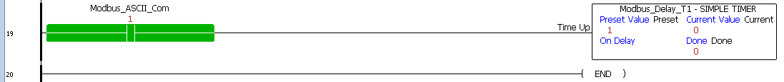
The ASCII OUT and IN instructions will be used for communication. A 10-millisecond timer will be used between the ASCII OUT instructions for timing purposes.
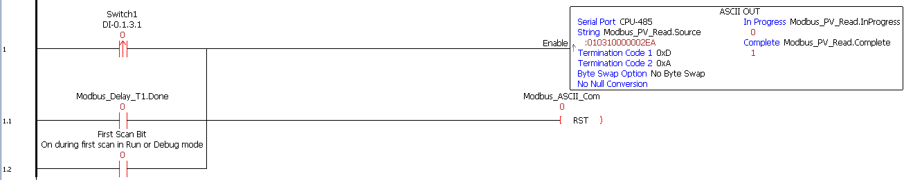
The program will read the set and present value from the Solo process temperature controller using the ASCII output instruction. This will be sent when switch 1 is turned on, the first scan (start communications), or after a time delay from the last communication.
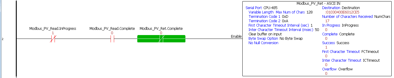
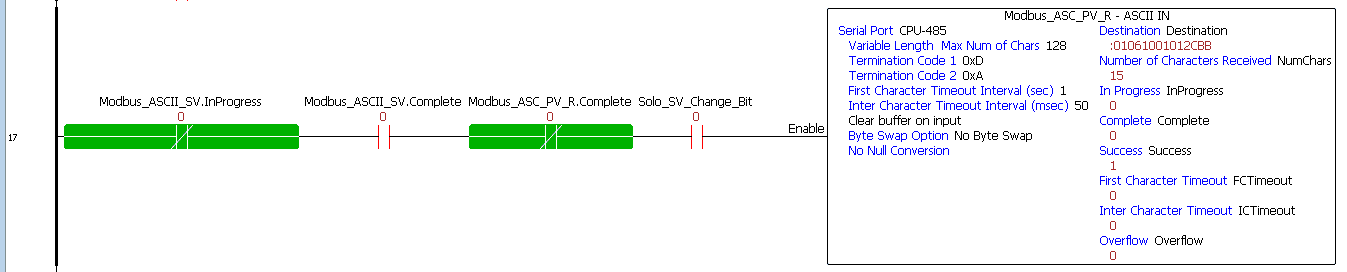
Once the ASCII output is not in process and is complete we will enable the ASCII input instruction. The data is stored as ASCII characters.

Once the return is complete we start a time delay before sending out the next ASCII characters.
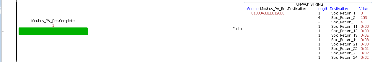
The returned string must be unpacked in order to see the actual values. Since we need to convert the string characters into HEX values, we are using destination tags of data type integer, 8 bit Unsigned. It takes 4 of these tags for every 4 digit hex value.
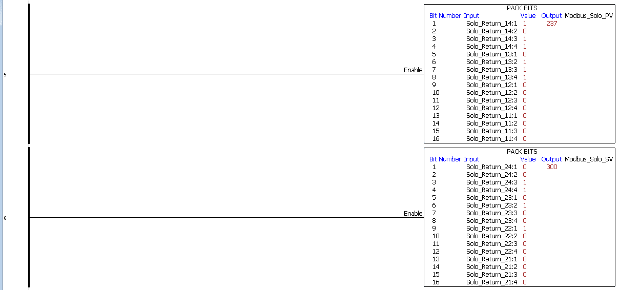
Once we have the 4 tags of 8-bit unsigned data, we use the pack bits to create the 16-bit word using 4 bits from each tag. This is done for the present value and the set value of the Solo controller.
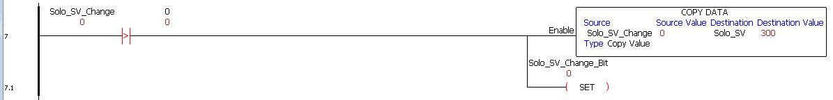
If the solo SV change value is greater than 0 then we will move the change value into the solo SV tag and set the change bit.
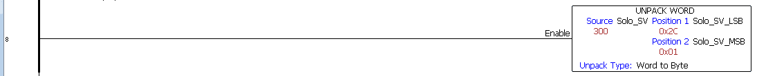
The solo SV tag is then unpacked into an LSB and MSB hex values. This will be used to calculate the LRC check characters.
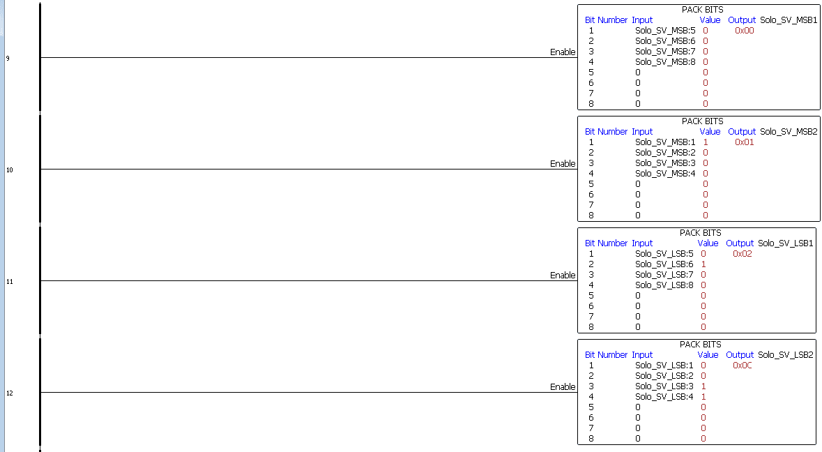
We use the pack bits instruction to separate the LSB and MSB hex values into 4 tags with a data type of 8-bit integer. This is necessary to convert the HEX values into ASCII latter in the program.
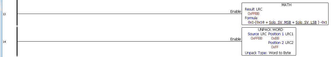
We now use math to calculate the LRC value of the message we are sending.
:0103061001XXXXYY is the command for writing the SV to the solo using Modbus ASCII. (XXXX is the set value and YY is the LRC). The LRC is calculated starting after the start character. (:)
(01+06+10+01) = 0x18
The math formula is 0x1 – (0x18 + Solo SV MSB + Solo SV LSB) – 0x1
The result is a 4 digit hexadecimal number. We use the unpack word to get the two least significant digits. This will be our LRC for the message.
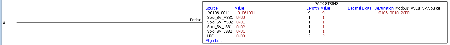
Pack string is now used to build the Modbus ASCII message to change the set value of the solo controller.
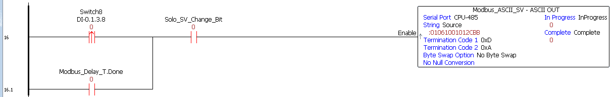
When the SV change bit is on and the first time delay communication is done, we will send the Modbus ASCII SV out port 3.
When the send is complete we will look for the response of the SV change.
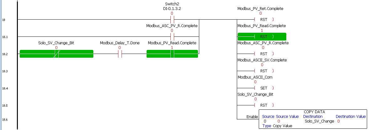
We will now reset all of the ASCII Out and In instructions. The change SV value is reset to 0. Only when the SV value is greater than 0 does the program writes the SV value to the solo controller. This will allow set value changes to be made also at the Solo controller.
After a time delay after the reset, communication can then start over again.
Testing the productivity 1000 sample program
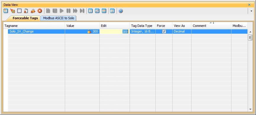
Using data view we can change the set value of the controller. See below for error codes that may be seen when troubleshooting your program.
Watch the video below to see the running and configuration of the Modbus ASCII Serial Communication from the Productivity 1000 Series PLC to the Solo Process Temperature Controller.
Solo Error Response Codes
Exception responses from the Solo process temperature controller will help to troubleshoot your communication.
Format:
Modbus Address + (function code + 80H) + Error code
Here are the response codes (error codes) that can be returned.
01H function code is not supported
02H Illegal function address
03H Illegal read/write word count
04H Data process fails
09H Checksum error
Note: 04H is often caused by writes to the solo, but not having parameter CoSH set.
Download the Productivity 1000 PLC program here.
Productivity 1000 Series PLC from Automation Direct
Overview Link (Additional Information on the Unit)
Configuration (Configure and purchase a system – BOM)
User Manual and Inserts (Installation and Setup Guides)
Productivity Suite Programming Software (Free Download Link)
This software contains all of the instruction sets and help files for the Productivity Series.
Modbus Learning Links:
Simply Modbus Frequently Asked Questions
Modbus TCP/IP Overview – Real Time Automation
All You Need to Know About Modbus RTU – Video
Watch on YouTube: Productivity 1000 Series PLC Modbus ASCII Protocol
If you have any questions or need further information please contact me.
Thank you,
Garry
If you’re like most of my readers, you’re committed to learning about technology. Numbering systems used in PLC’s are not difficult to learn and understand. We will walk through the numbering systems used in PLCs. This includes Bits, Decimal, Hexadecimal, ASCII and Floating Point.
To get this free article, subscribe to my free email newsletter.
Use the information to inform other people how numbering systems work. Sign up now.

The ‘Robust Data Logging for Free’ eBook is also available as a free download. The link is included when you subscribe to ACC Automation.