Did you know that understanding edge triggers can drastically improve your PLC understanding? How one-shots work within the PLC scan is vital in programming PLCs. In this post, we’ll dive into the world of programmable logic controllers and explore the techniques and strategy secrets you need to know to trigger your edges precisely and accurately.
We will demonstrate the secrets with the free Do-More Designer Software and PLC simulator. Whether you’re a seasoned PLC programmer or just starting, this post has valuable insights and practical tips to take your edge-triggering skills to the next level. So, what are you waiting for? Let’s unlock the secret to ONE SHOT edge triggers in PLC scanning!
Previously in this BRX series PLC, we have discussed:
System Hardware – Video
Unboxing – Video
Installing the Software – Video
Establishing Communication – Video
Firmware Update – Video
Numbering Systems and Addressing – Video
First Program – Video
Monitoring and Testing the Program – Video
Online Editing and Debug Mode – Video
Timers – Video
Counters – Video
High-Speed IO – Video
Compare Instructions – Video
Math Instructions – Video
Program Control – Video
Shifting Instructions – Video
Drum Instruction – Video
Serial Communication – Modbus RTU to Solo Process Temperature Controller – Video
Data Logging – Video
Email – Text SMS Messaging Gmail – Video
Secure Email Communication Video
AdvancedHMI Communication – Modbus TCP – Video
Analog IO – System Configuration – Video
HTTP JSON Instructions – Video
Analog Dusk to Dawn Program – Video
INC DEC 512 Registers for DMX512 – Video
PID with PWM Output – Video
PID Ramp Soak Profile – Video
Do-More Simulator MQTT Publish / Subscribe – Video
BRX Do-More PLC MQTT Communications – Video
Stride Field Remote IO Modules Modbus TCP Ethernet
– Unboxing SIO MB12CDR and SIO MB04ADS Video
– Powering and Configuring Video
BRX Do-More PLC to Stride Field IO Modbus TCP – Video
BRX Do-More PLC Ethernet Remote IO Controller BX-DMIO
– Unboxing BX-DMIO Video
– Configuration and Programming Video
Modbus RTU TCP Remote IO Controller BX-MBIO
– Hardware Video
– Powering and Configuring Video
BRX Do-More PLC to Modbus Remote IO Controller BX-MBIO – Video
Modbus ASCII Protocol – Video
Peerlink Ethernet Communication – Video
HTTP Web Server – Video
Dynamic Web Pages – Video
BRX Do-More PLC FTP Client Get Put – Video
Do-More Designer Element Browser – Video
BRX Do-More PLC High-Speed Input Counter – Video
BRX Do-More PLC High-Speed Input Timer – Video
BRX Do-More PLC High-Speed Input Pulse Catch – Video
BRX Do-More Simple Modbus Serial Communication – Video
BRX Do-More PLC Using Modbus IO Scanner Profile – Video
UPDATE Your BRX Do-More PLC Firmware Made EASY! – Video
Our entire BRX Do-More series can be found here.
The programming software and manuals can be downloaded from the Automation Direct website free of charge. Watch the video below to see the firmware update on the BRX Do-More PLC.
Introduction to PLC Inputs and Edge Triggers
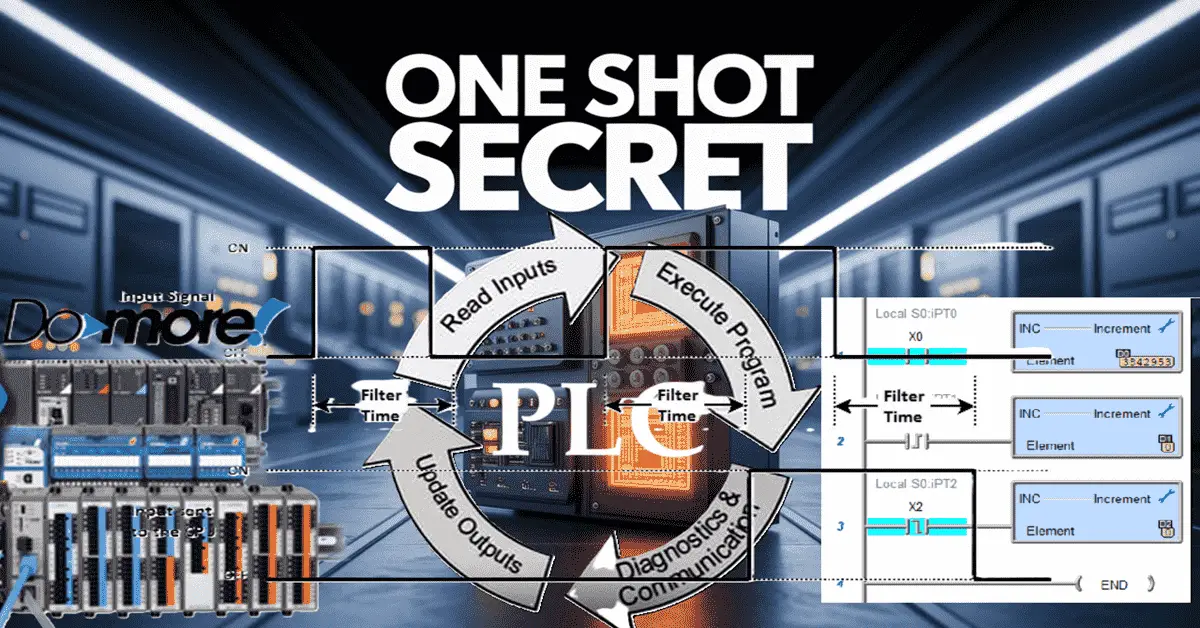
The fundamental operation of Programmable Logic Controllers (PLCs) scan refers to the cyclical process where the controller reads inputs, executes the control logic, and updates outputs.
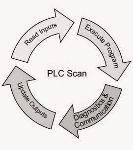
This scan is the heartbeat of automated systems, ensuring seamless operation and precise control. Inputs to the PLC are like the eyes of the control system. They let us see what the system or machine is doing.
All PLCs will have input filters. This is the minimum time required to register that an input is on. Edge triggers, a key concept in PLC programming, are essential for capturing specific events or conditions in your PLC program. Positive and negative edge triggers detect changes in input signals, triggering actions based on these transitions. Harnessing the power of edge triggers within PLC programming, you can optimize control systems, streamline operations, and elevate the performance of your industrial processes.
PLC Scan Read Input Filters
Start the Do-More Designer Programming Software. This entirely free, fully functional package includes a PLC simulator. It will program the entire Do-More Series of controllers, like the BRX, H2, and T1H. Start a new project by selecting the new offline icon on the main page.
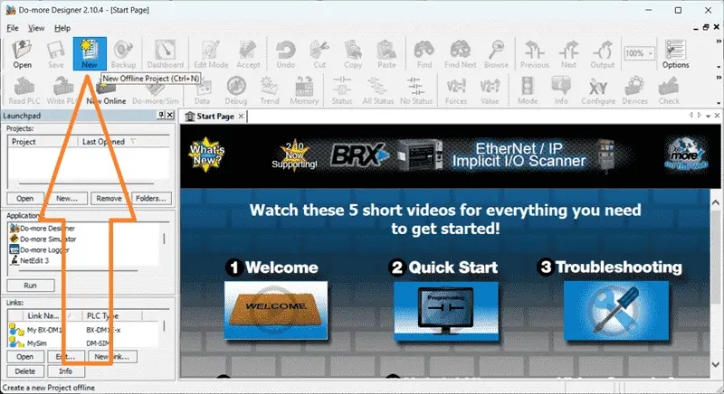
This can also be done using the main menu | File | New Project | Offline… Alternatively, you can also use the shortcut combination of Ctrl + N. We can select the controller we wish to program when the new offline project window appears.
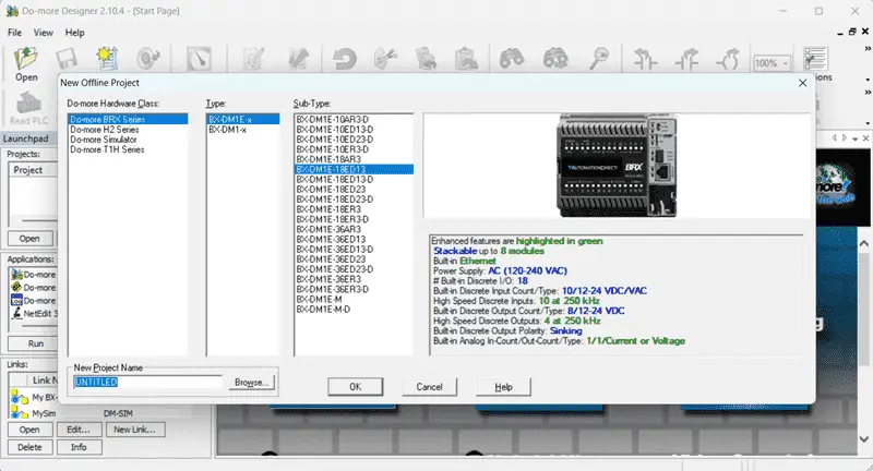
In our case, we will select the BX-D1ME-18ED13 controller. Leave the title of our project as the default, as we are just demonstrating. Select OK. Call up the system configuration window from the main menu | PLC.
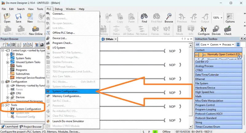
This can also be called up by selecting system configuration under tools in the project browser window. Each PLC software differs regarding the filters’ location or whether they can be set. See the documentation for your controller.
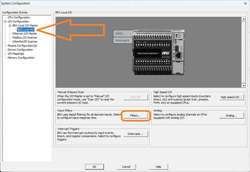
Select the BRX Local I/O on the left-hand side of the System Configuration window. Then select Filters… under the input filter heading.
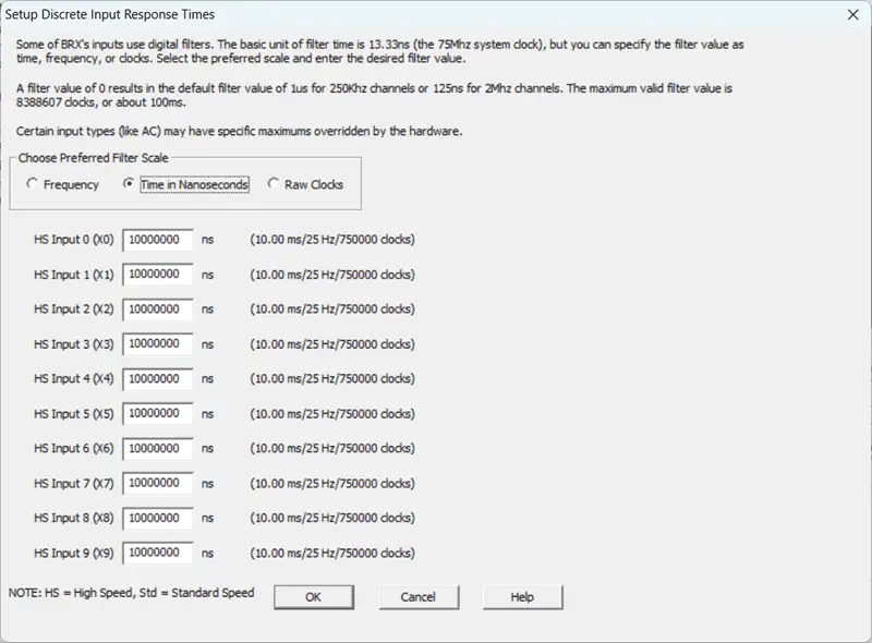
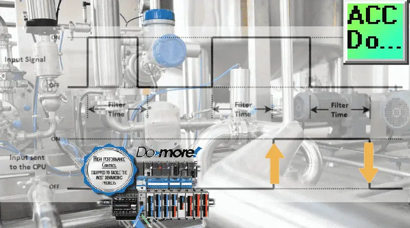
The Setup Discrete Input Response Time window will be displayed. Here we can adjust the filter time of the inputs. I like to view this screen in time (nanoseconds) because I do not have to calculate frequency based on the 75MHz clock. We can have input responses from 1 microsecond to 100 milliseconds, or 0.0000001 seconds to 0.1 seconds.
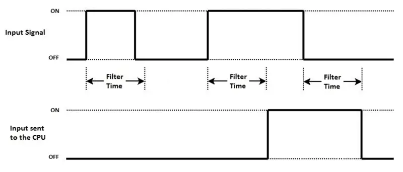
If the actual input signal is shorter than the filter time, the PLC will disregard the signal. When the input is on longer than the filter time, then the PLC will send this to the CPU. This input will be recognized as being on. When the input turns off, the filter time is added to the signal to the CPU.
Watch the video below to see this in action.
As mentioned previously, all PLCs will have input filter times. You may have to review the specifications for your controller to determine what minimum frequency or time is required to send the input to the CPU so it can be used in your program.
PLC Scan Execute Program
Ladder logic is the most common of the five recognized PLC programming languages. Our Do-More Designer software will only program in ladder logic. The cyclic nature of the PLC scan allows your program to be scanned rapidly. We will demonstrate this with the D0-More Designer PLC Simulator. Start a new offline program using the simulator.
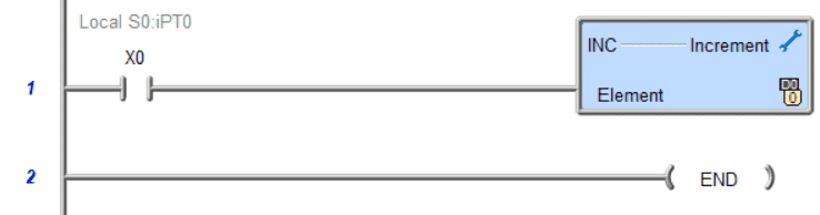
A normally open contact X0 will input an increment D0 instruction.
Connect to the simulator, download, and run the program.
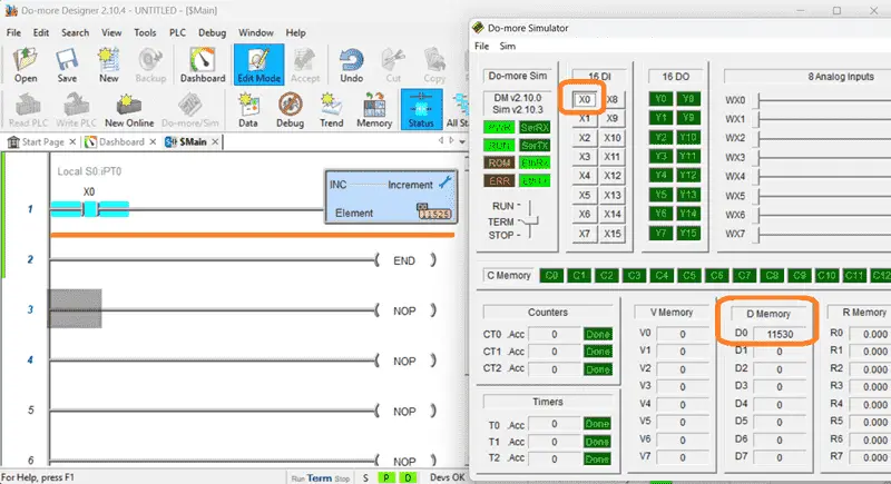
When we turn on X0, the increment instruction will add one to D0. Since we have a cyclic scan, this will happen every time X0 is on. If we need to do this only once, then this is where our leading or trailing edge one shots come in.
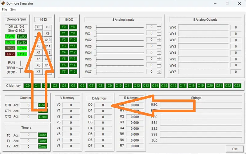
Note that our simulator works independently of the Do-More Designer programming software. It must communicate with the simulator, so there is a slight lag in the numbers within D0.
Ladder Logic and ONE SHOT Implementation
Leading Edge detection is known by several different names within PLC programming. ONE Shot, Positive Edge, Negative Edge, Differentiate Up, Differentiate Down, etc. Please refer to your PLC manual for the terminology used in your PLC controller.
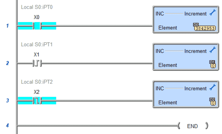
We will insert a new rung and add a Leading Edge One-Shot contact for input X1. This will increment the D1 register. The third rung will have a Trailing Edge One-Shot contact for input X2. This will increment the D2 register.
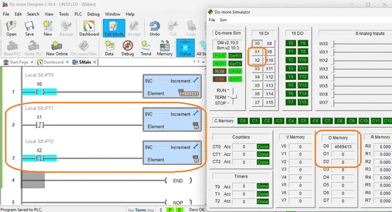
Accept the changes to the program and write them to the PLC Simulator.
Turn on X1 and X2.
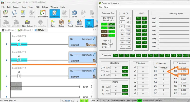
D1 register has now been incremented just once. This is because we turned on X1, which changed the input from off to on. The instruction in the scan cycle detected this leading edge and activated the output, incrementing D1.
Note that D2 did not increment. This is because X2 is looking for the trailing edge or a transition from on to off.
Turn off X1 and X2.
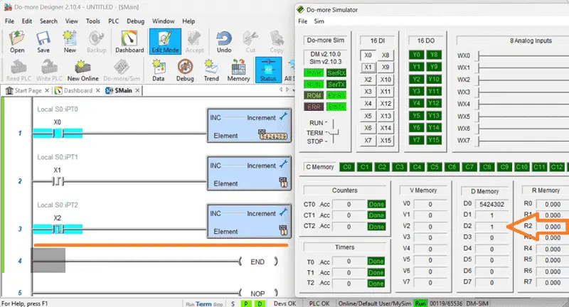
The D2 register has now been incremented just once. This is because we turned off X2, which changed the input from on to off. The instruction in the scan cycle detected this trailing edge and activated the output, incrementing D2.
D1 did not increment again because X1 only looks for a leading edge or transition from off to on. The power of ONE SHOT triggers capturing specific events or conditions with precision and accuracy.
Multiple Inputs One One-Shot
PLCs will often have one-shot instructions built into specific instructions. One of the most common instructions is the counter.
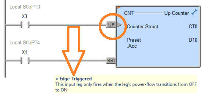
In the Do-More Designer programming software, the leading/trailing edge is represented by a triangle on the input leg of the instruction. This example will increment the counter only on the leading edge of the input conditions.
Please refer to your controller manual for specific instructions on the input signal conditions.
So far, we have just looked at individual contacts for our leading and trailing edge one-shots. PLCs also have output instructions that can set one-shots within your program. These are usually used with internal memory bits because they are only on for one scan cycle at a time.
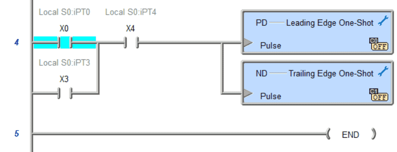
Add a positive differential (PD) Leading Edge One-Shot and a negative differential (ND) Trailing Edge One-Shot output instructions. We will set the exact parallel and series contacts to each rung.
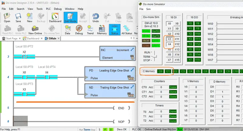
We can now utilize our program’s internal contact bits C0 and C1. This integration enhances the responsiveness of control systems and opens up a world of possibilities for fine-tuning automation processes to meet your diverse industrial needs.
By mastering these triggers, you not only enhance your technical skills but also contribute to the advancement of industrial control systems. Embrace the power of ONE SHOT Edge Triggers to revolutionize your approach to PLC programming.
For those looking to expand their knowledge in industrial automation and control systems, exploring additional resources and further reading can be invaluable. Whether you are a beginner seeking to grasp PLC basics or an experienced professional aiming to enhance your skills, the right educational materials can make a significant difference in your understanding and proficiency. To review our PLC guide and approaches to creating PLC programs, click here. Click here to learn more about the Do-More Designer Software program.
Watch the video below to see how edge trigger one-shots work.
Click here to download the PLC Simulator program that we just created.
Our entire BRX Do-More series can be found here. The FAQ page for the BRX Do-More can be found here.
BRX Series PLC from Automation Direct – Power to deliver
Overview Link (Configure and purchase a system)
Manuals and Product Inserts (Installation and Setup Instructions)
Do-More Designer Software (Free Download Link) – The software will contain all of the instruction sets and help files for the BRX Series PLC.
Watch on YouTube: The Secret to Perfect PLC Edge Detection Revealed!
If you have any questions or need further information, please contact me.
Thank you,
Garry
If you’re like most of my readers, you’re committed to learning about technology. Numbering systems used in PLCs are not challenging to learn and understand. We will walk through the numbering systems used in PLCs. This includes Bits, Decimal, Hexadecimal, ASCII, and Floating Point. To get this free article, subscribe to my free email newsletter.
Use the information to inform others how numbering systems work. Sign up now. The ‘Robust Data Logging for Free’ eBook is also available for free download. The link is included when you subscribe to ACC Automation.