The newest Do-More Designer Programming Software (2.9) version includes a Modbus I/O Scanner. This Modbus scanner will simplify Modbus RTU serial communications to any device. Communications are done independent of the PLC scan time and will have little or no ladder logic for the program.
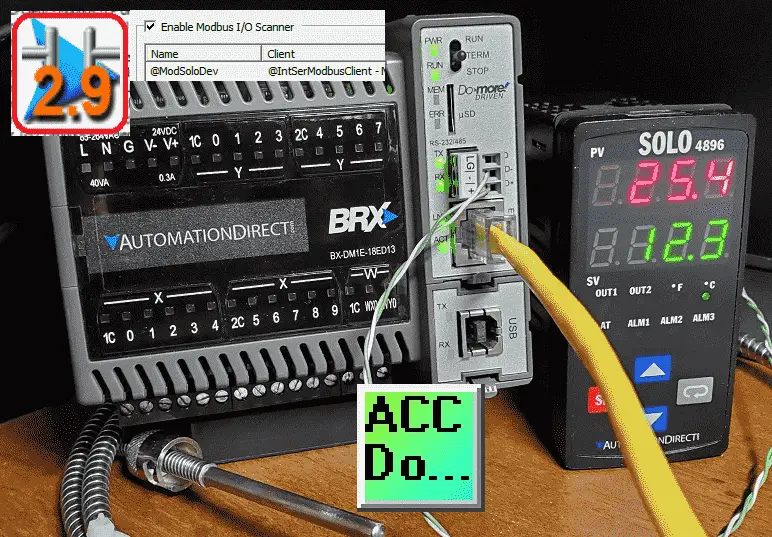 We will be communicating to a Solo process temperature controller via Modbus RTU RS485. (twisted pair) Setting up the Modbus IO scanner and reading the present value (PV) and set value (SV) of the Solo. We will also write the set value (SV) located within the BRX Do-More controller. Communications will happen without using any ladder logic code. Let’s get started.
Previously in this BRX series PLC, we have discussed:
System Hardware – Video
Unboxing – Video
Installing the Software – Video
Establishing Communication – Video
Firmware Update – Video
Numbering Systems and Addressing – Video
First Program – Video
Monitoring and Testing the Program – Video
Online Editing and Debug Mode – Video
Timers – Video
Counters – Video
High-Speed IO – Video
Compare Instructions – Video
Math Instructions – Video
Program Control – Video
Shifting Instructions – Video
Drum Instruction – Video
Serial Communication – Modbus RTU to Solo Process Temperature Controller – Video
Data Logging – Video
Email – Text SMS Messaging Gmail – Video
Secure Email Communication Video
AdvancedHMI Communication – Modbus TCP – Video
Analog IO – System Configuration – Video
HTTP JSON Instructions – Video
Analog Dusk to Dawn Program – Video
INC DEC 512 Registers for DMX512 – Video
PID with PWM Output – Video
PID Ramp Soak Profile – Video
Do-More Simulator MQTT Publish / Subscribe – Video
BRX Do-More PLC MQTT Communications – Video
Stride Field Remote IO Modules Modbus TCP Ethernet
– Unboxing SIO MB12CDR and SIO MB04ADS Video
– Powering and Configuring Video
BRX Do-More PLC to Stride Field IO Modbus TCP – Video
BRX Do-More PLC Ethernet Remote IO Controller BX-DMIO
– Unboxing BX-DMIO Video
– Configuration and Programming Video
Modbus RTU TCP Remote IO Controller BX-MBIO
– Hardware Video
– Powering and Configuring Video
BRX Do-More PLC to Modbus Remote IO Controller BX-MBIO – Video
Modbus ASCII Protocol – Video
Peerlink Ethernet Communication – Video
HTTP Web Server – Video
Dynamic Web Pages – Video
BRX Do-More PLC FTP Client Get Put – Video
Do-More Designer Element Browser – Video
BRX Do-More PLC High-Speed Input Counter – Video
BRX Do-More PLC High-Speed Input Timer – Video
BRX Do-More PLC High-Speed Input Pulse Catch – Video
Our entire BRX Do-More series can be found here.
The programming software and manuals can be downloaded free from the Automation Direct website.
Watch the video below to see the operation of the Modbus IO scanner on the BRX Do-More PLC. This will be Modbus RTU (RS485) to a Solo Process Temperature Controller.
Communication RS485 Wiring Solo to BRX Do-More PLC
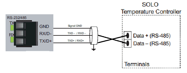 RS485 is a two-wire serial communication media, and Modbus RTU will be the protocol used. This protocol is a master/slave type of configuration. The BRX will be the master and will communicate with the Solo slave. There can be only one master on the serial network and up to 247 slaves with a repeater. Without a repeater, you can connect 32 slaves with RS485. These can be different devices.
Communication Setting for the Solo Process Temperature Controller
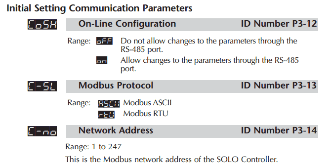
The solo process temperature controller needs to be set up before we can communicate with it. The default setting is ‘Off’ for the On-Line Configuration. Here is the way to change into the different modes in the Solo.
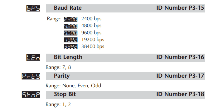
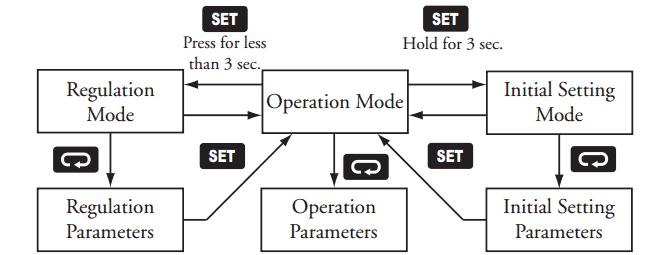 In the Initial Setting Mode, we will change the on line configuration to on and make the changes to the Modbus settings: 9600 Baud, Even, 8 Data Bits, 1 Stop Bit, Modbus RTU Format. We will leave the default unit number as 1.
 Our controller is now set to communicate.
Download the documentation, configuration, and monitoring software at the following URL link:
http://support.automationdirect.com/products/solo.html
Configuration of the BRX PLC Serial RS485 Port
We will now set up the RS485 serial communication port with the specifications that match the setting of the Solo controller.
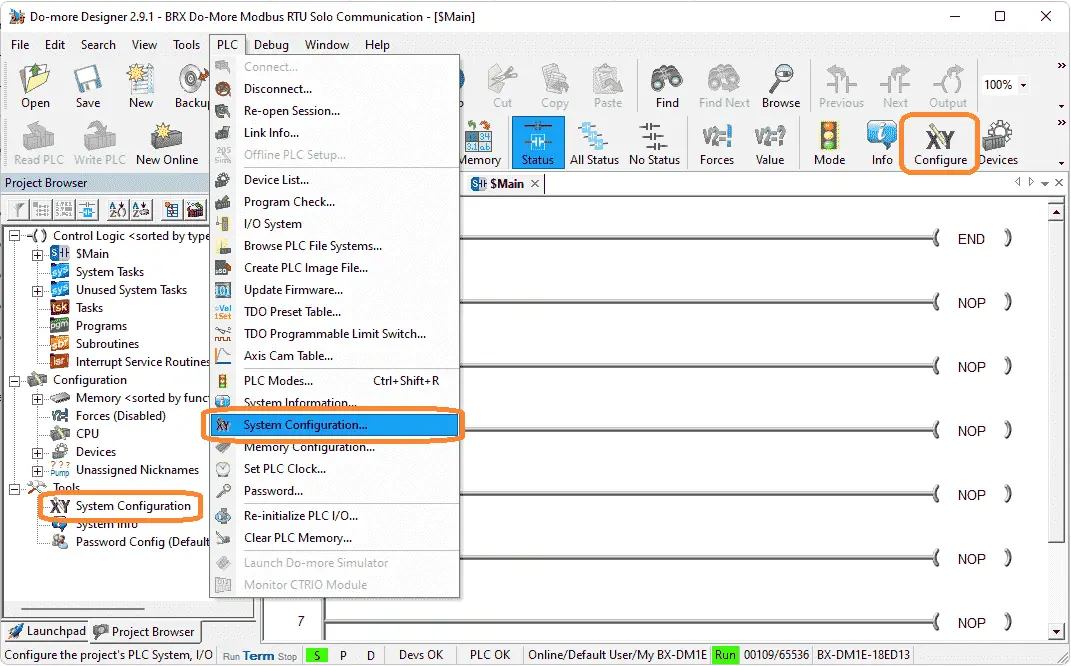 Select System Configuration… under the main menu | PLC, or select the icon on the main menu. Alternatively, you can also choose System Configuration under the Tools menu of the Project Browser window.
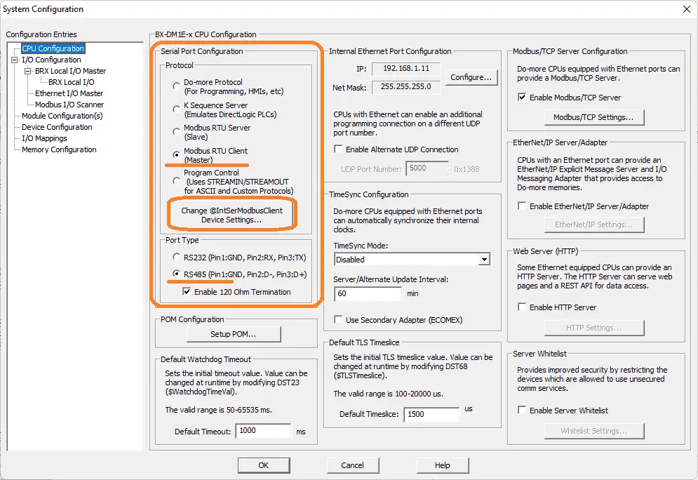 The CPU Configuration will be selected as the default display under configuration entries on the left side of the system configuration window.
Select Modbus RTU Client (Master) as the protocol. Select RS485 as the port type and enable the 120 Ohm termination resistor.
@IntSerModbusClient is the default name for this Modbus Client in the BRX PLC. Select the Change @IntSerModbusClient Device Settings… button.
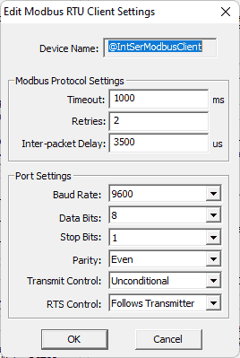 Enter the Modbus settings: 9600 Baud, Even, 8 Data Bits, 1 Stop Bit to match our Solo Process Temperature Controller. Select OK. This will bring us back to our system configuration window.
Modbus IO Scanner Configuration
Select the Modbus I/O Scanner. This is located under the BRX Local IO Master in the IO Configuration of the system configuration window.
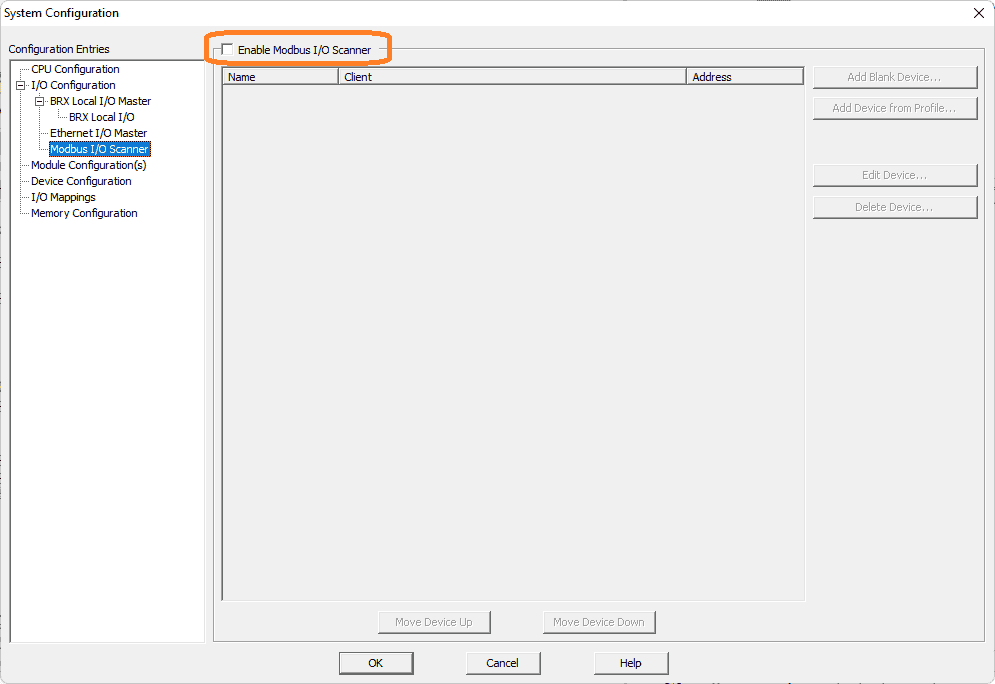 Select enable Modbus I/O Scanner.
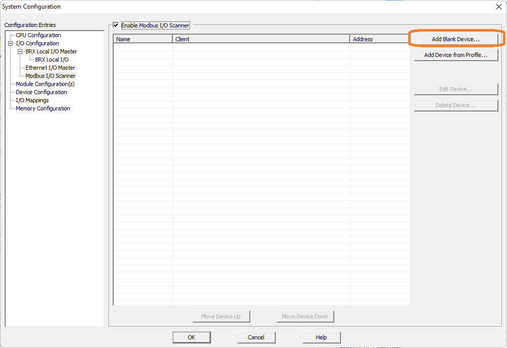 Several profiles have been set up in the software. These profiles will allow you to use what has been proven in the field. The Solo Process Temperature Controller does not currently have a profile. Select Add Blank Device…
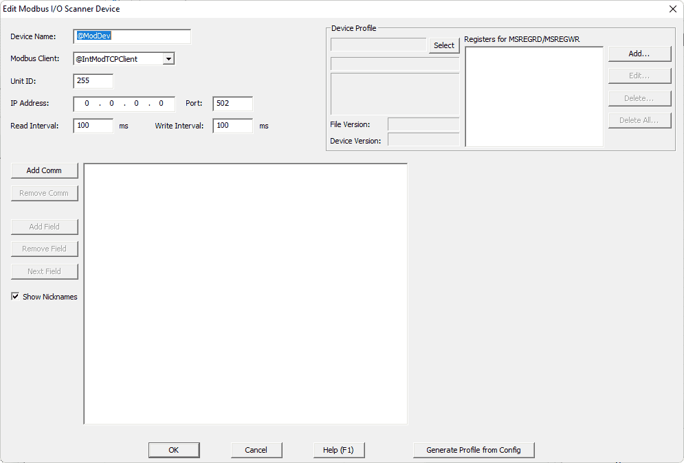 Device Name: We will change this to @ModSoloDev, so we know what it is doing.
Modbus Client: Change this to the @IntSerModbusClient port that we set up above.
Unit ID: 1 – This is set for our Solo controller.
Read Interval: 100 ms – This is the reading interval independent of the BRX PLC scan time. We will leave this a 100-millisecond default. (10 times per second)
Write Interval: 100 ms – This is the writing interval independent of the BRX PLC scan time. We will leave this a 100-millisecond default. (10 times per second)
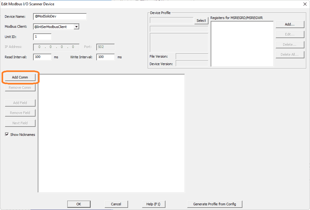 Select the Add Comm button.
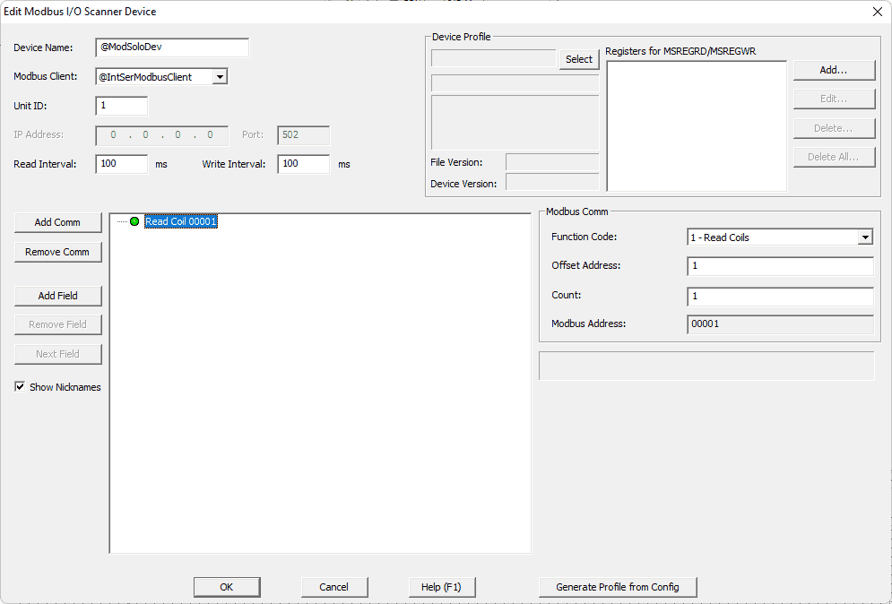 The Read Coil 00001 shows up as a default. The settings on the right-hand side will set the Modbus communication. The links below will explain these Modbus function codes. The Modbus addresses for the Solo process temperature controller can be found in chapter 7 of the manual. See the link below.
 Set the function code to 3 – Read Holding Registers
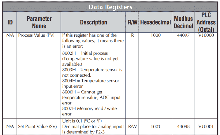
The Offset Address will be 4097.
The count is the number of registers to read. Set this for two so we will read both the present value (PV) and set value (SV).
Based on the function code, you will see the Modbus address of 44097-44098. This matches the Modbus Decimal address from the chart above.
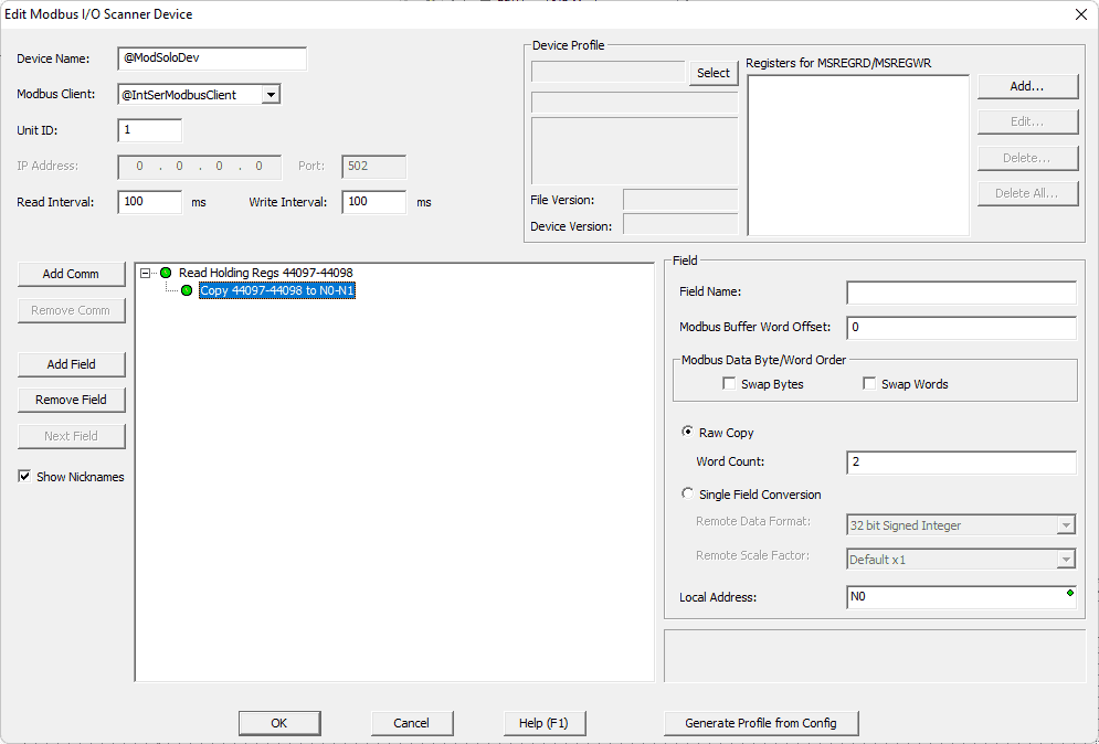
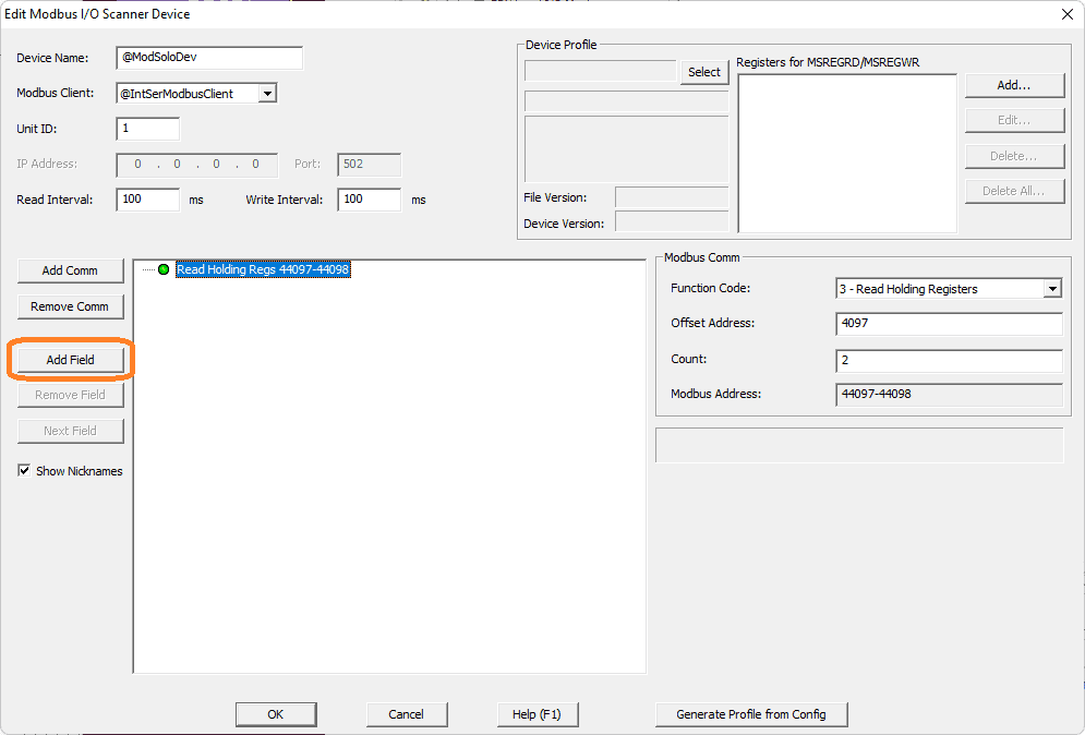 Select Add Field. The field will manipulate the data read from the Modbus Solo.
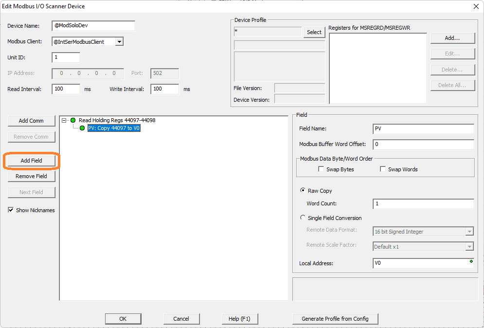
 Set the field name to PV (Present Value). Since the PV value is a 16-bit single word, we will put the word count as one and keep the raw copy. The Modbus buffer word offset will be left as the default 0 because this is the first word being read from the Solo.
Note: Depending on the information coming from the Modbus device, we can modify it to suit the data it represents. Example: 32-bit float number.
Set the local address to V0.
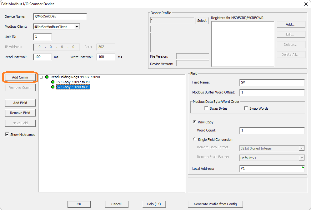
 Select the Add Field button again.
Our second Modbus address is the set value SV. We will place this in address V1 of the BRX PLC. The Modbus buffer word offset is 1, and we have a raw copy of the 1-word count.
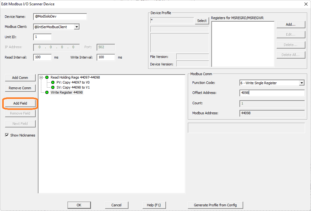
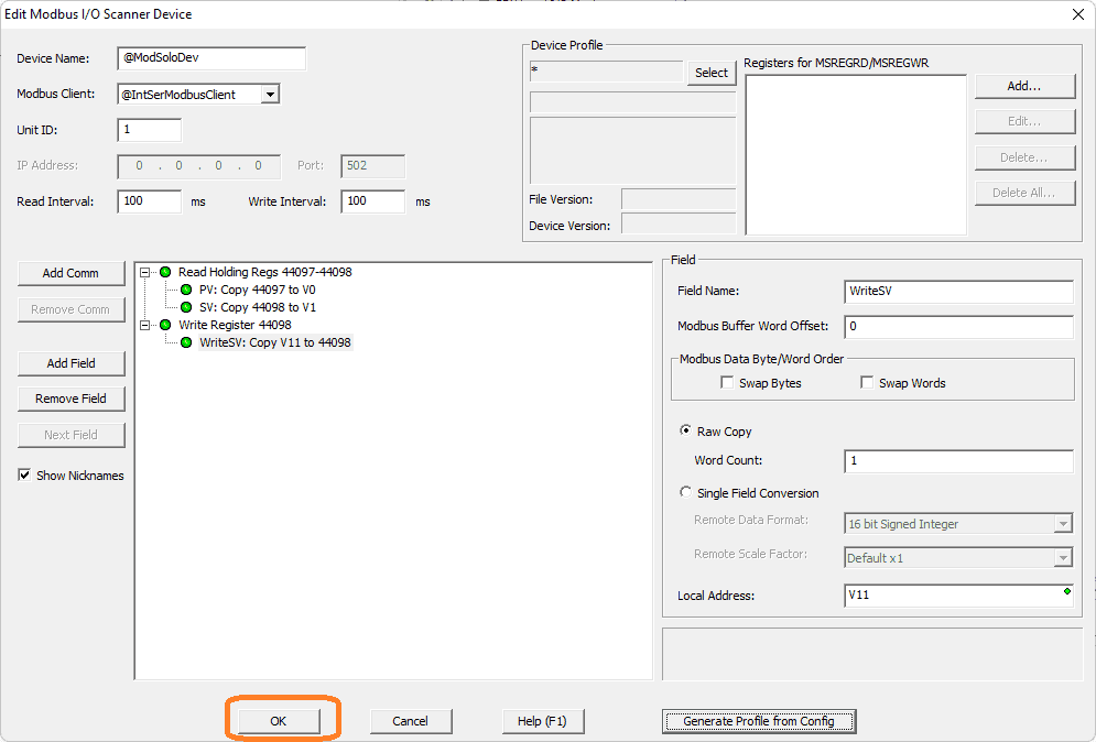
 Select the Add Comm button again. We want to use the function code 6 – Write Single Register. The offset will be 4098, making the Modbus Address 44098.
Select Add Field.
 The field name will be “WriteSV.” Using the raw copy word count of 1, we will use the value in V11 to write to our Solo controller.
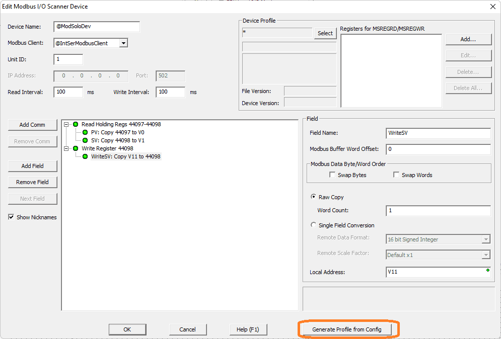 Select the Generate Profile from the Config button.
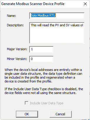 You can provide a name and description of the configuration. Select OK.
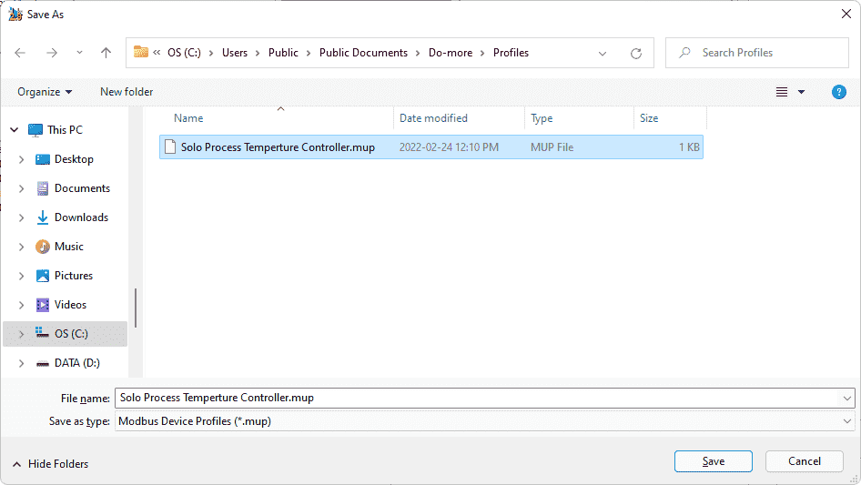 Name the Modbus Device Profile. The extension will have a “.mup.” Select Save.
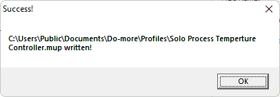 Our configuration has now been saved.
 Select OK.
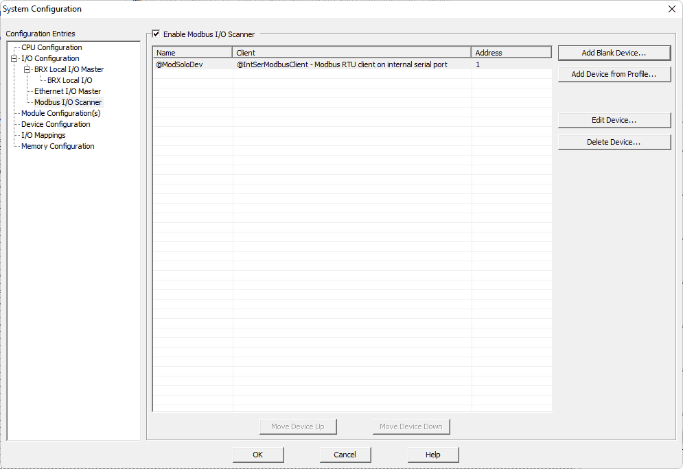 Our Modbus I/O Scanner can now be seen in the system configuration window.
Select OK to close the window.
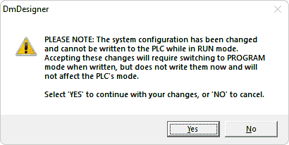 Since we have changed the BRX PLC system configuration, a warning message will be displayed. Select Yes.
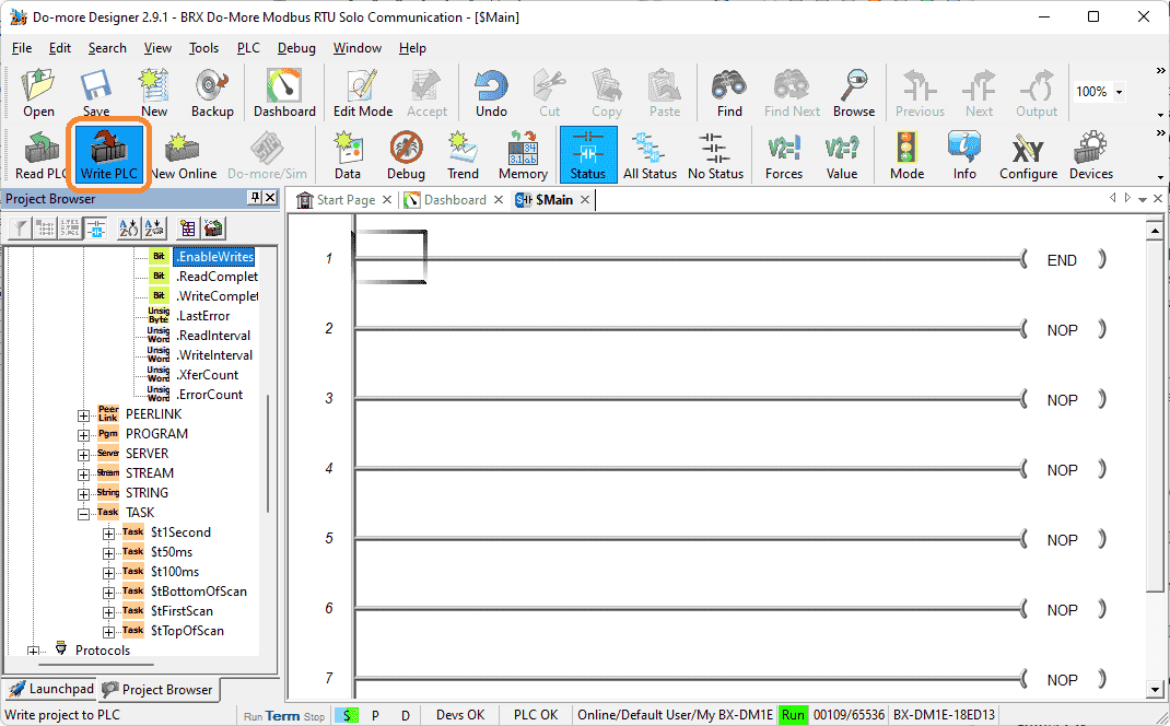 Write the PLC project and configuration to the connected PLC.
Monitoring the Modbus IO Scanner
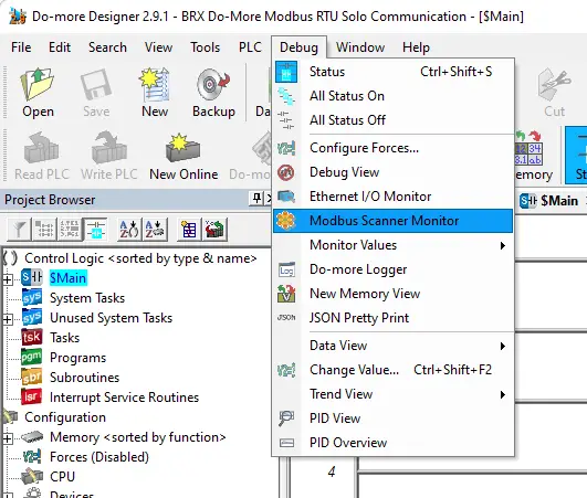
Select Modbus Scanner Monitor from the main menu | Debug.
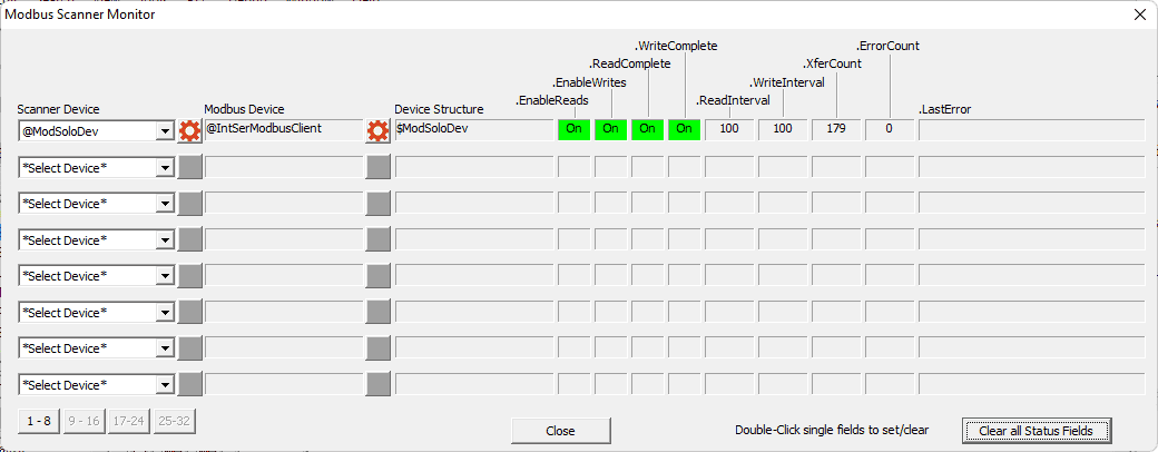
 We can quickly see our Modbus Scanner working.
 Using the Data View, we can all up the registers that we specified to see the PV and SV of the Solo temperature controller.
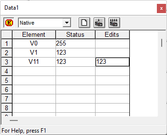 Change the value in V11. This will automatically send the new SV of the Solo. All done without the need for ladder logic or a unique timing code.
Watch the video below to see how to communicate using a Modbus IO scanner to the Solo Process Temperature Controller.
Download the BRX Do-More program here.
BRX Series PLC from Automation Direct – Power to deliver
Overview Link (Configure and purchase a system)
Manuals and Product Inserts (Installation and Setup Instruction)
Do-More Designer Software (Free Download Link) – The software will contain all the instruction sets and help files for the BRX Series PLC.
Watch on YouTube: BRX Do-More Simple Modbus Serial Communication
If you have any questions or need further information, please contact me.
Thank you,
Garry
If you’re like most of my readers, you’re committed to learning about technology. Numbering systems used in PLCs are not challenging to learn and understand. We will walk through the numbering systems used in PLCs. These numbering systems include Bits, Decimal, Hexadecimal, ASCII, and Floating Point. To get this free article, subscribe to my free email newsletter.
Use the information to inform other people how numbering systems work. Sign up now. The ‘Robust Data Logging for Free’ eBook is also available for free download. The link is shown when you subscribe to ACC Automation.