The Machine Simulator (MS) is part of the EasyPLC software suite. It has many built-in machines that are used to show different programming techniques. The warehouse stacker example is one of these machines. Pallets are loaded and unloaded into the stacker machine. A maximum of 30 pallets can be stored. The stacker will work as a FIFO (First In First Out) device. This means that the pallets are stored in a sequence and retrieved in a sequence.
 The Click PLC will be used to program this virtual 3D stacker machine. Indirect addressing (pointers) will be used to track the positions on the stacker to store and retrieve the pallets. Using the Click Plus PLC, we will connect to the warehouse stacking machine. This will be done using Modbus TCP (Ethernet) for communications. Using the five steps for program development we will show how this FIFO is programmed. Let’s get started.
Learn PLC programming the easy way. Invest in yourself today. See below on how to receive a 10% discount on this already cost-effective learning tool.
Previously we have done the following:
Easy PLC Installing the Software – Video
EasyPLC Software Suite – Quick Start – Video
Click PLC – Easy Transfer Line Programming – Video
Productivity PLC Simulator – Chain Conveyor MS – Video
Do-More PLC – EasyPLC Box Selection Program – Video
Click PLC EasyPLC Gantry Simulator – Video
Click PLC Simple Conveyor EasyPLC – Video
EasyPLC Paint Line Bit Shift – BRX Do-More PLC – Video
Click PLC – EasyPLC PLC Mixer Programming – Video
Define the task: (Step 1 – Easyplc Warehouse Stacker)
The first step of PLC program development is to determine what must be done. Start the EasyPLC Machine Simulator (MS). Select the start button on the main page or select machines from the main menu on the top of the machines simulator window.
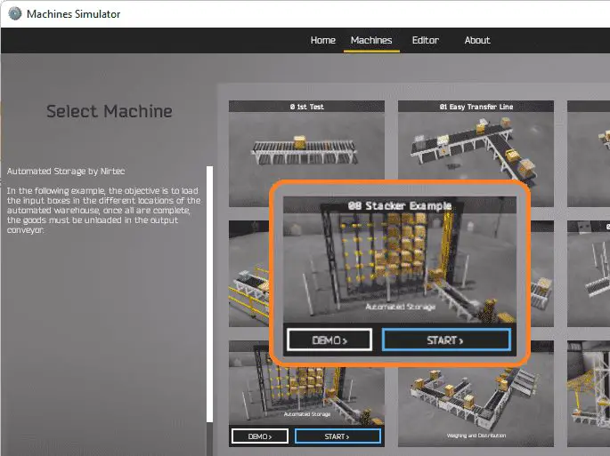 All the available machines will now be displayed. Click on the “08 Stacker Example”. This is the example that we will be programming. To the left of the screen, information will be displayed on what the machine needs to do as well as some of the inputs and outputs required for the program.
The objective is to load the input boxes in the different locations of the automated warehouse. Once all are complete, the goods must be unloaded in the output conveyor. Select the start button.
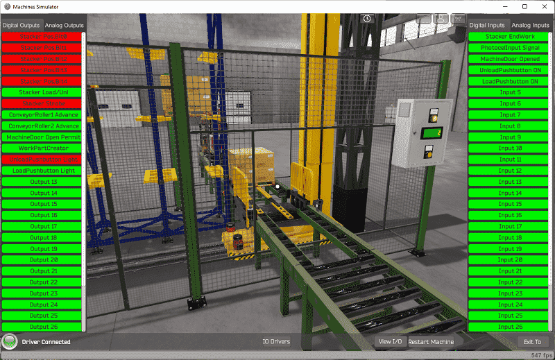
 The machine simulator has a demo mode for the built-in machines. However, this machine has been modified from the original scene. The modification now includes a control panel. The modified machine can be downloaded from the link below. This must be copied into the machine simulator folder.
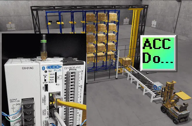
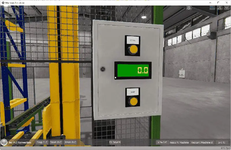 The control panel has two lighted pushbuttons and a display. The display will be used for the number of stored pallets on the stacker. The load pushbutton will flash when we are loading a pallet into the warehouse stacker. When the stacker is full (30 pallets) the load light will be solid. The unload button will flash when the unload sequence is being performed. When the stacker is empty (0 pallets) the unload light will be solid.
The warehouse stacker door will be allowed to open when we are not loading or unloading pallets in the stacker. Unload and load pushbutton lights will be on when the door is opened.
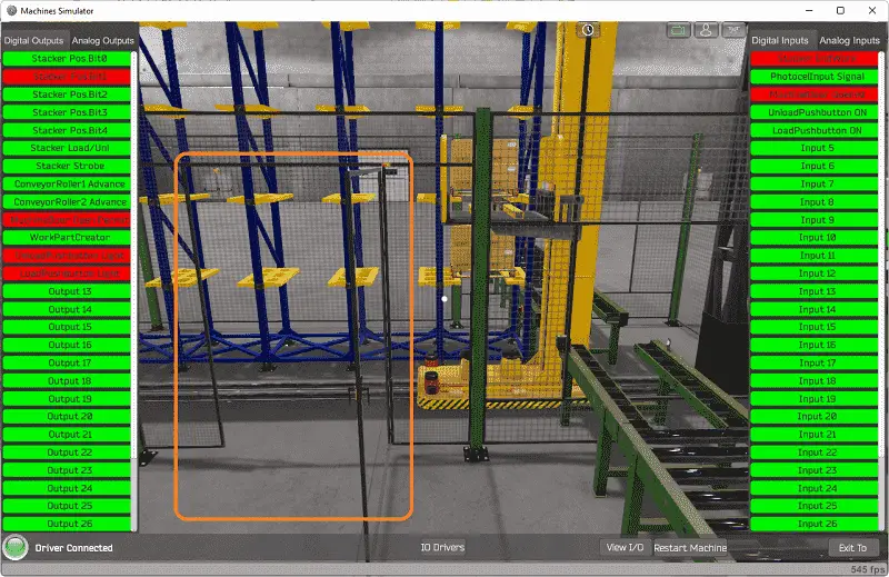
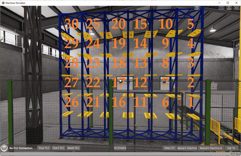 The stacker has the above numbers for each of the locations. This warehouse stacker will use FIFO. (First In First Out) When the load pushbutton is pressed, the first pallet will be loaded into position 1. The next pallet will be loaded into position 2, etc. When the unload pushbutton is pressed, the first loaded pallet (position 1) will be unloaded. The next press of the unload button will unload the next position. If no pallets are left in the stacker, the positions are reset back to position 1 on the first load.
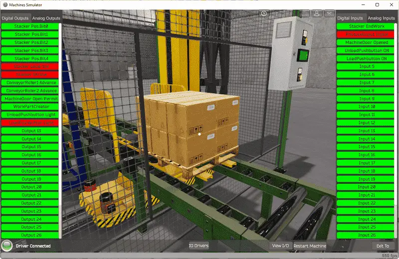
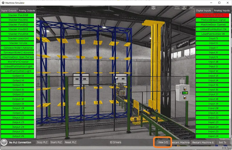 Select the “View I/O” button on the bottom of the machine simulator window. This will allow you to view the inputs on the right-hand side of the window and set the outputs on the left side of the window.
The stacker has the following outputs; 5 position bits, load/unload bit, strobe bit. If we wanted to load a pallet from the input conveyor, we would ensure all the position bits are off. Then turn on the load/unload bit and the strobe bit.
The stacker end work bit input will turn on once the movement has finished loading.
Loading the pallet into the stacker position 5, we would turn on bit 0 and bit 2 of the positions. (These bits use a binary sequence.) Turn off the load/unload to indicate that we are unloading the pallet. Then turn on the strobe. After the movement is complete the stacker end work input will be turned on.
Unloading the warehouse stacker would involve loading the pallet using the position bits and load. To move to the output conveyor, turn on all of the position bits.
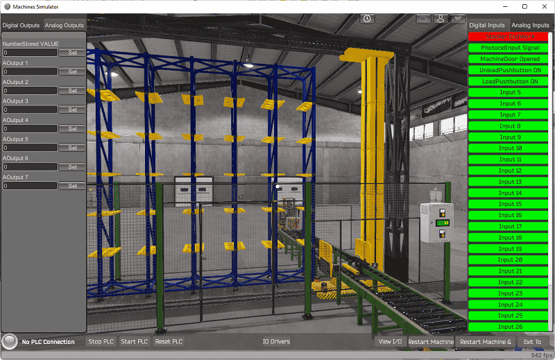 The number of pallets stored can be displayed on the control panel by using the first analog output value.
Move around the 3D virtual environment. There are three icons on the top of the window that will allow you to move around this 3D environment. The first icon is the default selection. This will allow you to move around without bumping into the components. The first-person mode will mimic a person in your 3D learning world. The last icon will automatically show you around this virtual environment.
Watch this video to see the operation of the Click PLC EasyPLC Warehouse Stacker.
Watch on YouTube: Click PLC EasyPLC Warehouse Stacker Operation
Once we understand what must be done, we can move on to the next step in the PLC program development. Watch the video below to see all five steps of the programming development for the warehouse stacker.
Define the Inputs and Outputs: (Step 2 – Easyplc Warehouse Stacker)
The View IO at the bottom of the machine simulator window will display the inputs and outputs required for this warehouse stacker example.
The EasyPLC stacker example will require 13 digital outputs and 5 digital inputs. 1 analog output is also used for the number of pallets in the stacker.
If you are unsure as to what output or input is doing, start the stacker machine line in Start mode. Select the View IO on the bottom middle of the machine simulator window. You can manually run the mixer without any control or PLC connected.
Clicking on the outputs will allow you to manually turn them on. You can then monitor the inputs to see their operation. The restart button on the bottom of the machine simulator window will reset the scene back to the start.
The following table will define the inputs and outputs (IO) and Modbus addresses in the Click PLC that we will use for this program.
| Digital Type | Description | Click PLC Modbus Address | Machine Simulator Modbus Address |
| PLC Output – MS Input | Stacker Pos. Bit 0 | 8225 – Y101 | 8224 |
| PLC Output – MS Input | Stacker Pos. Bit 1 | 8226 – Y102 | 8225 |
| PLC Output – MS Input | Stacker Pos. Bit 2 | 8227 – Y103 | 8226 |
| PLC Output – MS Input | Stacker Pos. Bit 3 | 8228 – Y104 | 8227 |
| PLC Output – MS Input | Stacker Pos. Bit 4 | 8229 – Y105 | 8228 |
| PLC Output – MS Input | Stacker Load/Unload | 8230 – Y106 | 8229 |
| PLC Output – MS Input | Stacker Strobe | 8231 – Y107 | 8230 |
| PLC Output – MS Input | Conveyor Roller 1 Advance Input | 8232 – Y108 | 8231 |
| PLC Output – MS Input | Conveyor Roller 2 Advance Exit | 8233 – Y109 | 8232 |
| PLC Output – MS Input | Machine Door Open Permit | 8234 – Y110 | 8233 |
| PLC Output – MS Input | Work Part Create | 8235 – Y111 | 8234 |
| PLC Output – MS Input | Unload Pushbutton Light | 8236 – Y112 | 8235 |
| PLC Output – MS Input | Load Pushbutton Light | 8237 – Y113 | 8236 |
| PLC Input – MS Output | Stacker EndWork – Movement Finished | 100033 – X101 | 32 |
| PLC Input – MS Output | Photocell Input Signal – Load conveyor | 100034 – X102 | 33 |
| PLC Input – MS Output | Machine Door Opened | 100035 – X103 | 34 |
| PLC Input – MS Output | Unload Pushbutton ON | 100036 – X104 | 35 |
| PLC Input – MS Output | Load Pushbutton ON | 100037 – X105 | 36 |
| PLC Analog Output – MS Analog Input | Stacker Stored Pallets Display | 400001 – DS1 | 0 |
Note: The machine simulator will be offset by one on the Modbus Addresses.
Develop a logical sequence of operation: (Step 3 – Easyplc Warehouse Stacker)
A flow chart or sequence table is used to fully understand the process that needs to be controlled. It must also answer questions like the following:
What happens when electrical power and/or pneumatic air is lost? What happens when the input/output devices fail? Do we need redundancy?
This step is where you will spend most of your time. Understanding everything about the operation will save you time. It will help prevent you from continuously re-writing the PLC program logic. Knowing all these answers upfront is vital in the development of the PLC program.
The sequence of operation comes down to using indirect addressing (Pointers) in the PLC.
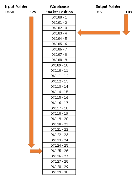 The positions of the warehouse stacker are numbered 1 to 30 in the PLC memory.
Input pointer will point to the current position being loaded. In our case above this is position 26. Once the load is complete the pointer will be incremented by 1. In our case, the next position is DS126 or position 27. If the incrementing goes past DS129 then we will reset back to DS100.
Output pointer will point to the current position to be unloaded. In our case above this is position 4. Once the unload sequence is complete the pointer will be incremented by 1. This will point in our case above to DS104 or position 5. If the incrementing goes past DS129 then we will reset back to DS100.
If the unload removes all the loaded pallets, then both pointers will be reset back to DS100.
A PLC programmer must know how everything about the sequence and operation of the machine before programming.
Ask questions or view existing documentation to ensure that you know the logical steps to the machine operation.
Develop the Click PLC program: (Step 4 – Easyplc Warehouse Stacker)
Writing the ladder logic code for the PLC example will be the next step in our program development. We will be using the Click programming software and a Click Plus PLC PLC.
The Click PLC Series will take you through installing the program, communicating to the controller, instructions, and addressing the controller.
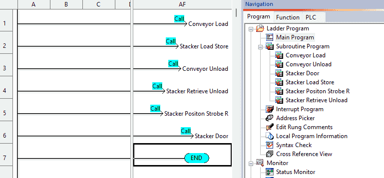 The main program calls six different subroutine programs. This makes up the entire ladder logic program to control the warehouse stacker.
Internal bits will control the sequence of operation for the program execution.
C1 – Conveyor Load
C2 – Stacker Load
C3 – Stacker Store
C6 – Conveyor Unload
C4 – Stacker Retrieve
C5 – Stacker Unload
C1 – Conveyor Load
The first subroutine called from the main program is Conveyor Load. This will control bit C1.
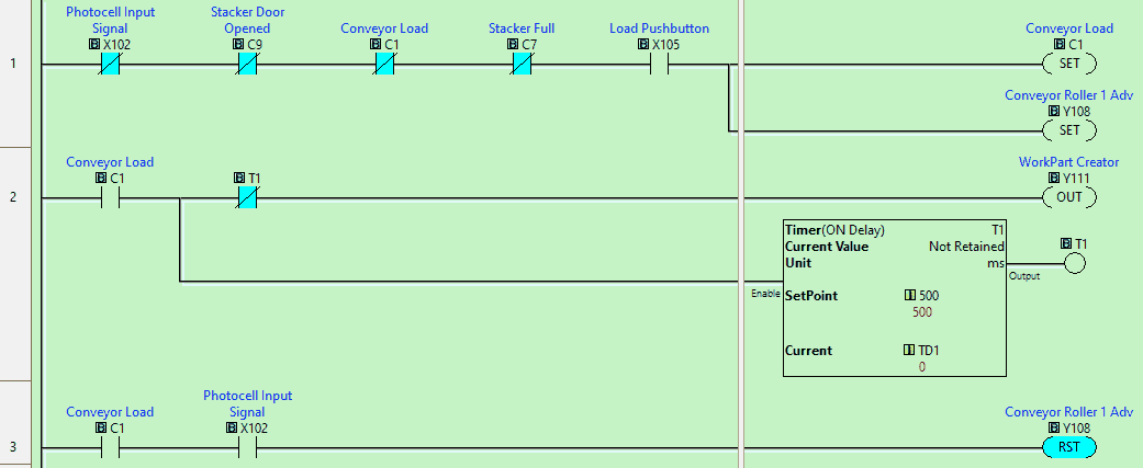 The incoming conveyor will be turned on when the load pushbutton is pressed. This will activate the create part output, putting a pallet on the conveyor. When the pallet reaches the end of the conveyor the incoming conveyor will stop.
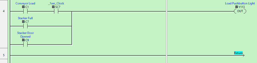 The load pushbutton will flash when the conveyor load signal C1 is on. The load pushbutton will be on steady when the stacker door is opened or when the stacker is full. (30 pallets)
Stacker Load and Store (C2 C3)
This routine will load the pallet from the incoming conveyor. It will then unload the pallet to the store position.
 We copy the position control bits from DS98. This control register contains the value of 0. This means that the control bits will all be off. We then set the stacker load-unload bit on or load. A timer is used to then trigger the stacker strobe after a time delay of 0.5 seconds. This will load the pallet from the incoming conveyor and put it on the stacker.
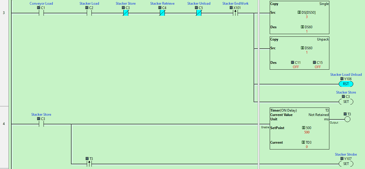 When the stacker finishes loading the pallet, it will set the position bits to the location of the stored pallet. This is done through indirect addressing or pointers in the Click PLC. In our case this is DS50. The screenshot above points to address DS102 which contains the value of 3. 3 is the position to store the pallet in the stacker. The stacker unloads bit is reset. A timer is used to then trigger the stacker strobe after a time delay of 0.5 seconds. This will unload the pallet from the stacker and put it in the stacker position specified.
 When the pallet is unloaded bits C1 to C3 are reset. This will stop the flashing loading button and be ready for the next pallet.
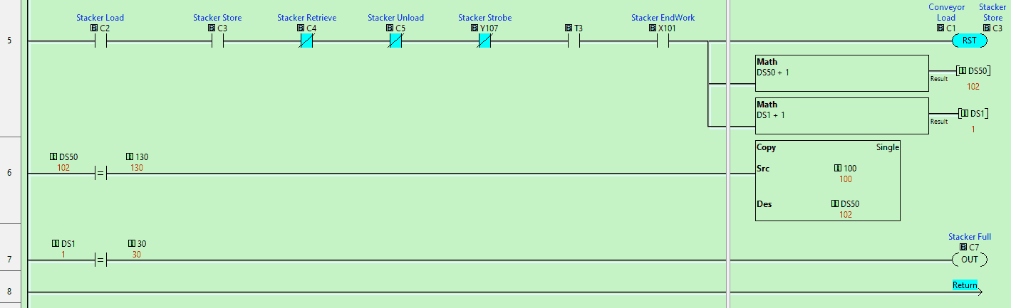
The indirect store address is incremented by 1 and the display on the control panel is incremented by 1. If the indirect store address is equal to 130 then it is reset to 100. This represents the 30 pallet storage locations.
If the display is equal to 30 pallets, then the stacker full bit is on.
C6 Conveyor Unload
This subroutine will control the pushbutton light and exit conveyor time.
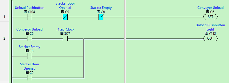 When the unload pushbutton is pushed, the conveyor unloads bit will be set. This will cause the unload pushbutton light to flash. The unload light will be solid when the stacker is empty (0 on the display) or when the stacker door is opened.
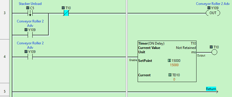 When the stacker unloads but turns off we will then turn on the exit conveyor. This will remain on for 15 seconds to allow the pallet to move down the conveyor and disappear.
Stacker Retrieve and Unload (C4 C5)
This routine will load the pallet from the stacker and unload the pallet to the exit position.
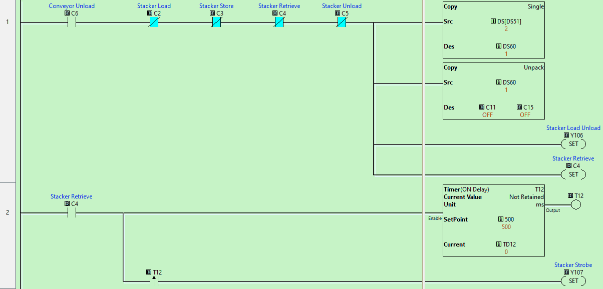 We copy the set the position bits to the location of the stored pallet. This is done through indirect addressing or pointers in the Click PLC. In our case this is DS51. The screenshot above points to address DS101 which contains the value of 2. 2 is the position to load the pallet in the stacker. The stacker load bit is set. A timer is used to then trigger the stacker strobe after a time delay of 0.5 seconds. This will load the pallet from the stacker and put it on the stacker.
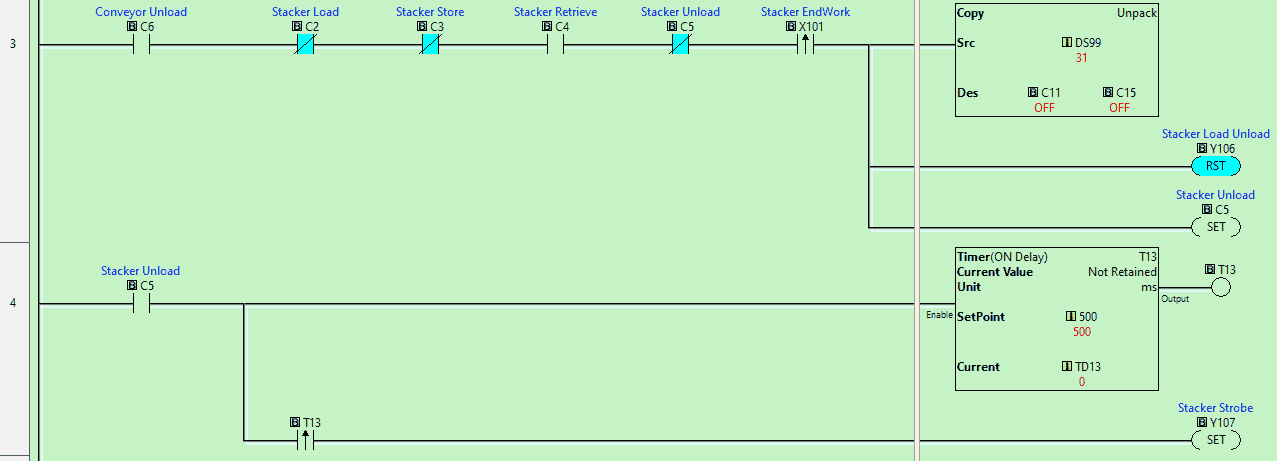 We copy the position control bits from DS99. This control register contains the value of 1F hexadecimal. This means that the control bits will all be on. We then set the stacker load-unload bit to off or unload. A timer is used to then trigger the stacker strobe after a time delay of 0.5 seconds. This will unload the pallet from the stacker and put it on the exit conveyor.
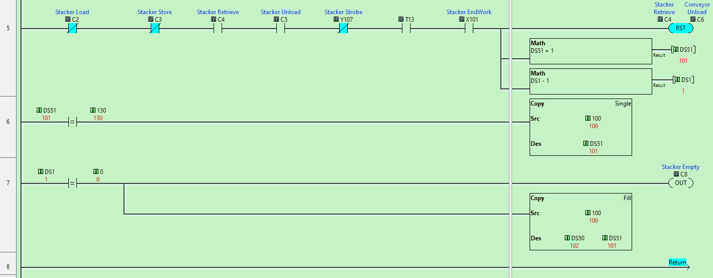 When the pallet is unloaded bits C4 to C6 are reset. This will stop the flashing unloading button and be ready for the next pallet.
The indirect unload address is incremented by 1 and the display on the control panel is decremented by 1. If the indirect store address is equal to 130 then it is reset to 100. This represents the 30 pallet storage locations.
If the display is equal to 0 pallets, then the stacker empty bit is on. We will also reset the pointers to the default of 100.
Stacker Position Strobe Reset
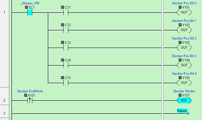 This will set the stacker position for each of the locations. The internal bits set in the previous subroutines will control bits C11 to C15. This is a binary number that specifies the stacker location. All off means to position the stacker at the input conveyor. All on means to position the stacker at the exit conveyor.
When the stacker movement is complete the stacker strobe is reset. This will all the next commands to be done.
Stacker Door Operation – Enable
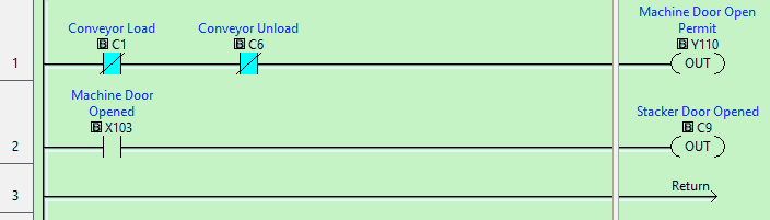 The stacker machine door will be permitted to open when we are not loading or unloading the stacker. If the door is opened C9 will activate causing the load and unload pushbutton lights to both be on.
In order to communicate to the EasyPLC Machine Simulator, we must set up the Ethernet Port on the Click PLC. Select main menu | PLC | System Configuration… Alternatively, you can also select system configuration under the function tab in the navigation menu of the Click programming software.
After calling up the system configuration, double-click on the communication port to display the settings. You can also call this directly by selecting the Com Port1 Setup.
A static (fixed) IP address is used on the network to ensure that we know where the PLC is after power interruptions. Make a note of this address so we can enter the information in the EasyPLC simulator.
Select Modbus TCP under the port settings to display the Modbus settings. This is enabled on port 502 as the default for the Click PLC.
Save and transfer the PLC program to the Click Plus PLC. Ensure that the PLC is in Run mode.
Watch the video below to see this PLC program in action
Test the program: (Step 5 – Easyplc Warehouse Stacker)
We will be using Modbus TCP on our Click Plus PLC to communicate to the EasyPLC Machine Simulator.
Call up the warehouse stacker machine simulator in start mode.
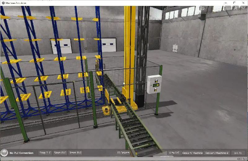
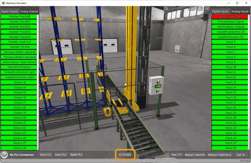 The status of the machine simulator will be along the bottom of the screen. Currently, we have no PLC connected. Select IO Drivers on the bottom middle of the screen.
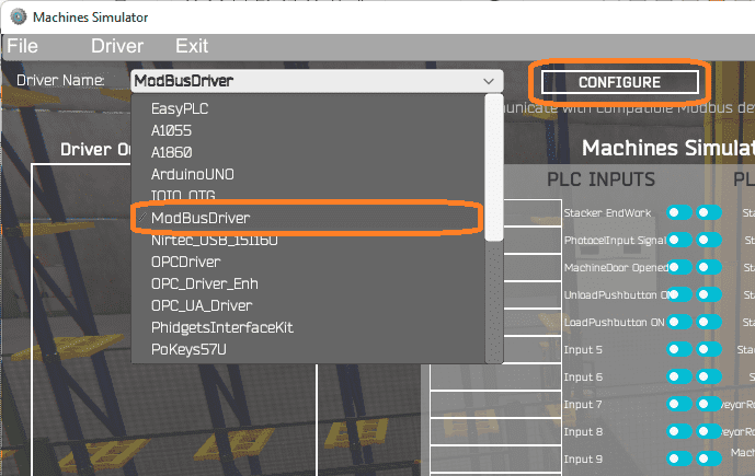 The EasyPLC driver is selected by default. Select the down arrow on the driver’s name. Under the driver pull-down menu, select “ModBusDriver”. This driver will communicate Modbus TCP (Ethernet) and Modbus RTU (Serial). Select the configure button.
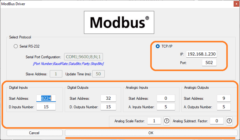 We can now enter the information for our Modbus driver. Select TCP/IP. This really means the Ethernet port on the computer will communicate to the PLC.
The digital inputs from MS to the Click PLC will be Y101 to Y107. This will start at address 8224 due to the offset of 1. Digital outputs from MS to the Click PLC will be X101 to X108. This will start at address32 due to the offset of 1. We are using one analog input for the stacker machine.
Select the OK button.
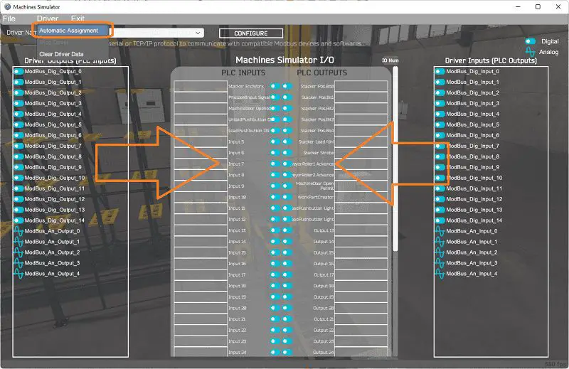 You will now see the inputs and outputs that we have specified for the Modbus driver. We can now manually assign the driver outputs to the PLC inputs and the driver inputs to the PLC outputs. However, the automatic assignment works well and will save you time.
Select Automatic Assignment from the driver option in the main menu.
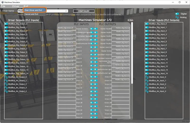 This will automatically assign the PLC IO to the Machine Simulator IO. Select start driver and exit from the main menu.
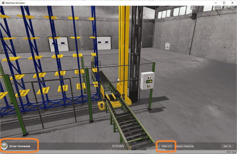 You will see on the bottom left side of the window that the driver is communicating to the PLC by the green light. Select view IO to see the input and output status of the machine simulator.
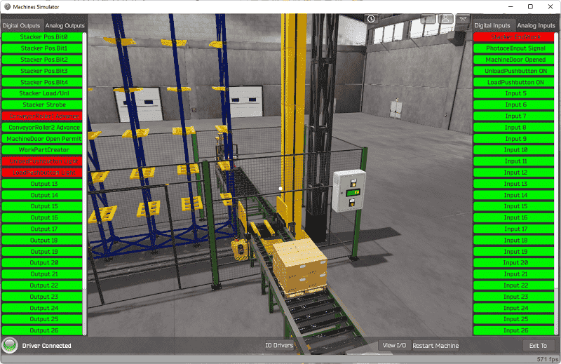 Ensure that the PLC is in run mode. We can see the operation of our industrial process mixer. Select the load push button on the control panel.
 The digital inputs and outputs of the MS will correspond to the PLC controller.
 Using Machine Simulator (MS) to test the program will ensure that our program works. Test out the door to ensure that you cannot load or unload if the door is opened. The unload button will remove the pallets in the stacker.
 Using the Data View window of the Click PLC programming software we can also watch the inputs and output operations.
 Watch the video below to see this on the operation.
Download the Click PLC sample program, indexing chart, and stacker machine file.
Watch the video below to see the five steps of program development applied to the warehouse stacker. The machine simulator is one of the best applications to help you learn PLC programming.
EasyPLC Software Suite is a complete PLC, HMI, and Machine Simulator Software package. This PLC learning package includes the following:
Easy PLC – PLC Simulation that will allow programming in Ladder, Grafcet, Logic Blocks, or Script.
HMI System – Easily create a visual human-machine interface (HMI)
Machine Simulator – A virtual 3D world with real-time graphics and physical properties. PLC programs can be tested using the EasyPLC or through other interfaces. (Modbus RTU, TCP, etc.)
Machine Simulator Lite – Designed to run on Android Devices.
Machine Simulator VR – Virtual Reality comes to life so you can test, train or practice your PLC programming.
Purchase your copy of this learning package for less than $75 USD for a single computer install, or less than $100 USD to allow different computers.
Receive 10% off the price by typing in ACC in the comment section when you order. http://www.nirtec.com/index.php/purchase-price/
Learn PLC programming the easy way. Invest in yourself today.
Watch on YouTube: Click PLC EasyPLC Warehouse Stacker Example
If you have any questions or need further information, please contact me.
Thank you,
Garry
If you’re like most of my readers, you’re committed to learning about technology. Numbering systems used in PLCs are not difficult to learn and understand. We will walk through the numbering systems used in PLCs. This includes Bits, Decimals, Hexadecimal, ASCII, and Floating Points.
To get this free article, subscribe to my free email newsletter.
Use the information to inform other people how numbering systems work. Sign up now.

The ‘Robust Data Logging for Free’ eBook is also available as a free download. The link is included when you subscribe to ACC Automation.