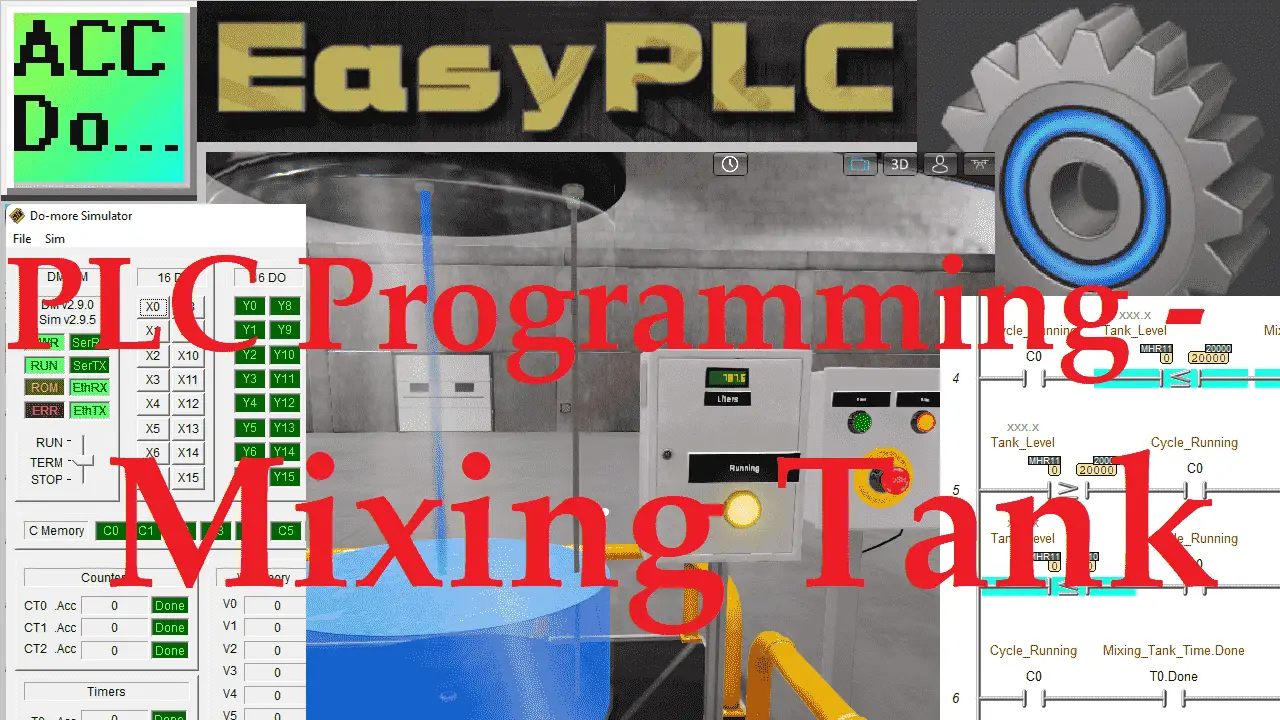
Previously we looked at the easy PLC machine editor design simulation. We created a mixing tank simulation using the EasyPLC machine editor. The tank included a control panel and operation indication. We will now use the Do-More designer programming software to program the ladder logic for this EasyPLC mixing tank application. The built-in simulator of the Do-More Designer programming software will be used to actually run the program and control our EasyPLC mixing tank machine. Development of this program will be done using the five steps for PLC programming. Let’s get started!
Learn PLC programming the easy way. See below how to receive a 10% discount on this already cost-effective learning tool. Invest in yourself today.
Previously we have done the following:
Easy PLC Installing the Software – Video
EasyPLC Software Suite – Quick Start – Video
Click PLC – Easy Transfer Line Programming – Video
Productivity PLC Simulator – Chain Conveyor MS – Video
Do-More PLC – EasyPLC Box Selection Program – Video
Click PLC EasyPLC Gantry Simulator – Video
Click PLC Simple Conveyor EasyPLC – Video
EasyPLC Paint Line Bit Shift – BRX Do-More PLC – Video
Click PLC – EasyPLC PLC Mixer Programming – Video
Click PLC EasyPLC Warehouse Stacker Example – Video
– Operation Video
EasyPLC Machine Simulator Productivity PLC Robotic Cell – Video
EasyPLC Simulator Robotic Cell Click PLC – Video
EasyPLC Simulator Robotic Cell BRX Do-More PLC – Video
– EasyPLC Factory Editor Robotic Cell Additions Video
4 Way Traffic Light PLC Program EasyPLC – Video
Rock Crusher Plant EasyPLC BRX Do-More – Video
Freight Carrier Weighing and Distribution EasyPLC – Video
EasyPLC Machining Center Loading Robots – Video
EasyPLC Palletizing Robot Programming Click PLC – Video
EasyPLC Machine Editor – Design a Simulation – Video
Define the task: (Step 1 – PLC Programming Mixing Tank)
The first step of PLC program development is to define the task to determine what must be done.
EasyPLC software suite contains over 40 machine simulator examples. You can use these to improve your PLC programming skills. Previously we created a mixing tank with a control panel and indication light.
Start the EasyPLC machine simulator. Select start on the home screen or select machines from the main menu. This will list all of the available machines for you to program.
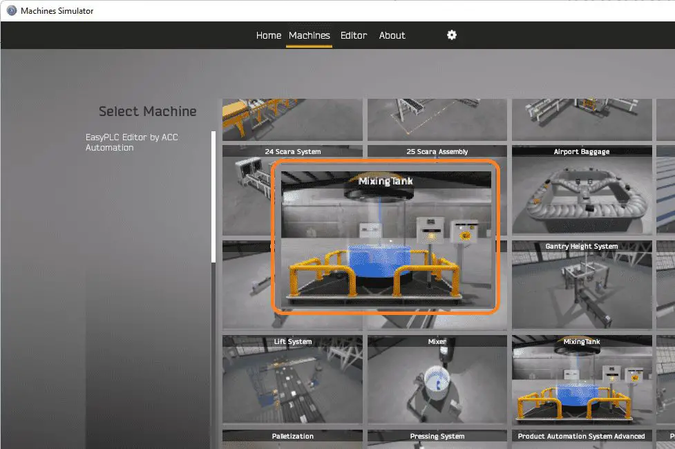 Scroll down until you see the mixing tank that we made previously.
Highlight this with your mouse and select start.
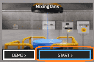 This will load our mixing tank simulation.
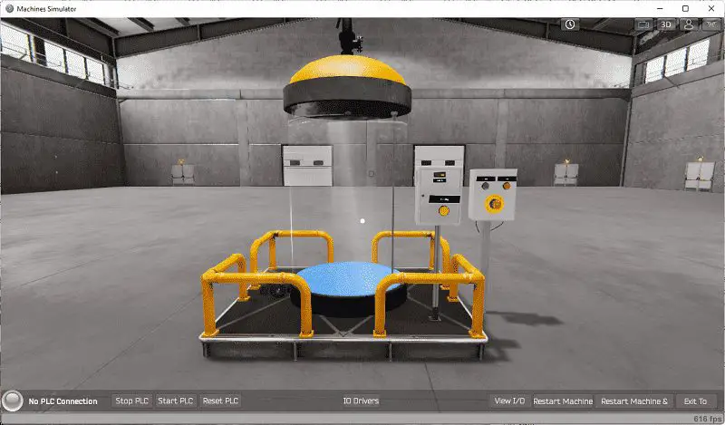
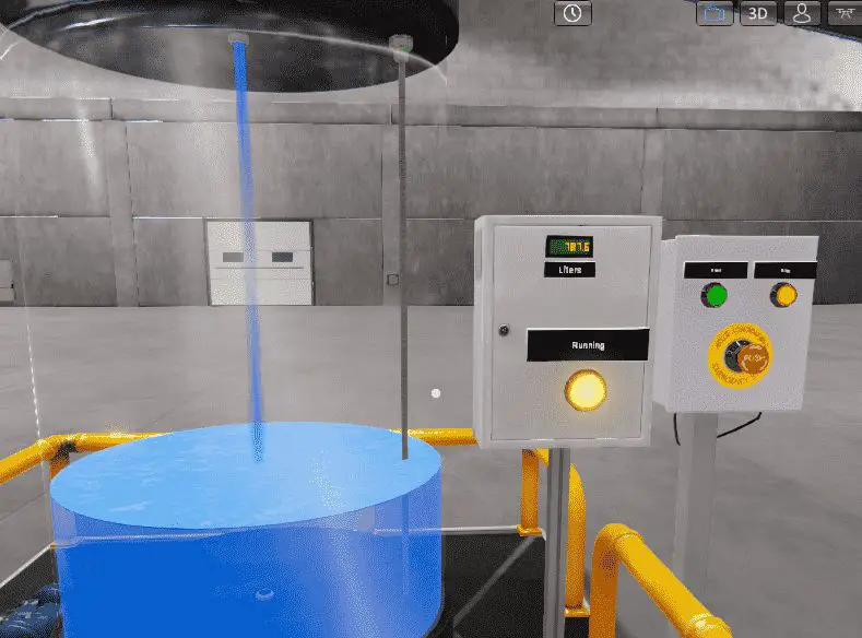
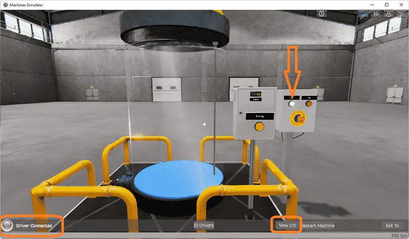
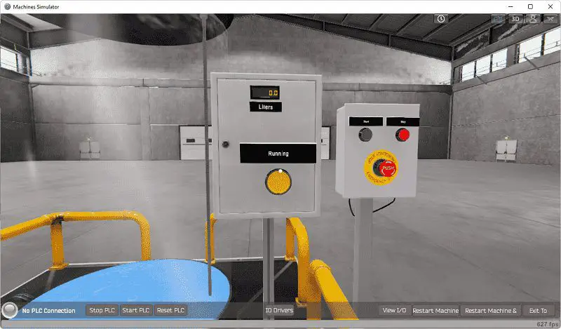 The control panel will control the mixing tank operation. Selecting start will start the mixing tank cycle. This will fill the tank, delay 20 seconds, then empty the tank. The stop or emergency stop buttons will stop the cycle. The start button will be used to continue the cycle.
Icons on the top right-hand side of the window will allow you to move around this 3D environment. Once we have a good understanding of what must be done, we can now move on to the next step in our PLC program development.
Define the Inputs and Outputs: (Step 2 – PLC Programming Mixing Tank)
The View IO at the bottom of the machine simulator window will display the inputs and outputs required for this mixing tank example.
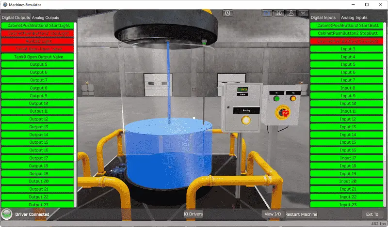
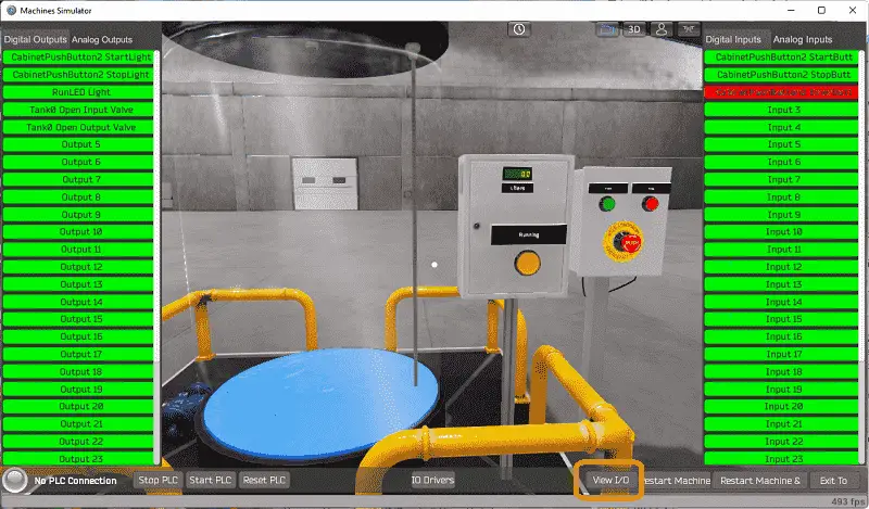 The EasyPLC mixing tank example will require 5 digital outputs and 3 digital inputs. Select the Analog outputs and inputs.
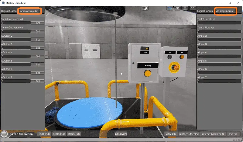 We will use the tank level analog to determine the height of the liquid in the tank.
The EasyPLC start mode will allow you to manually control the mixing tank simulator. This is ideal if you are unsure as to what output or input is doing.
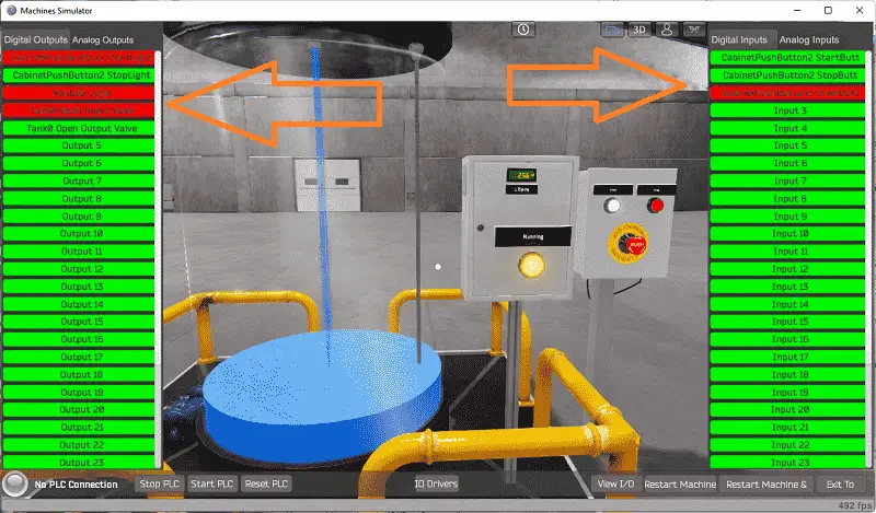 While viewing the IO on the bottom middle of the machine simulator window. You can manually run the mixing tank without any control or PLC connection. Select the digital outputs that you want to enable. The digital inputs will respond to these outputs.
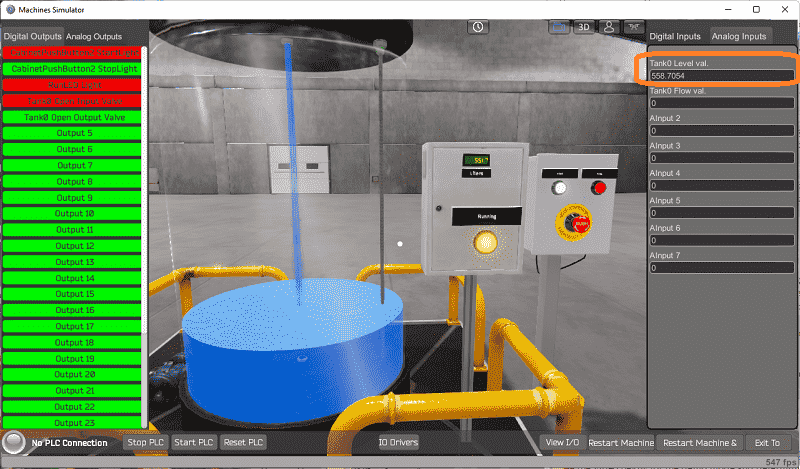 Select the analog inputs on the right-hand side, to watch the level of the liquid in the tank.
Move around the 3D environment and ensure that you know what each input and output represents.
The following table will define the inputs and outputs (IO) and Modbus addresses in the Do-More PLC that we will be using for this program.
| Digital Type | Description | Do-More PLC Modbus Address | Machine Simulator Modbus Address |
| PLC Output – MS Input | Start PB Light | MI1 – 10001 | 0 |
| PLC Output – MS Input | Stop PB Light | MI2 – 10002 | 1 |
| PLC Output – MS Input | Run LED Light | MI3 – 10003 | 2 |
| PLC Output – MS Input | Tank Open Input | MI4 – 10004 | 3 |
| PLC Output – MS Input | Tank Open Output | MI5 – 10005 | 4 |
| PLC Input – MS Output | PB Start | MC1 – 1 | 0 |
| PLC Input – MS Output | PB Stop | MC2 – 2 | 1 |
| PLC Input – MS Output | PB Emergency Stop | MC3 – 3 | 2 |
| PLC Analog Input – MS Analog Output | Tank Level XXXX.X | MHR11 – 11 | 10 |
Note: The machine simulator will be offset by one on the Modbus Addresses. See the video below for the demo mode and determining inputs and outputs.
Develop a logical sequence of operation: (Step 3 – PLC Programming Mixing Tank)
A PLC programmer must know how everything about the sequence and operation of the machine before programming. The mixing tank is an excellent way to learn to program. A flow chart, sequence table, or logical sequence is used to fully understand the process that needs to be controlled. It must also answer questions like the following:
What happens when electrical power and/or pneumatic air is lost? What happens when the input/output devices fail? Do we need redundancy?
This step is where you will spend most of your time. Understanding everything about the operation will save you time. It will help prevent you from continuously re-writing the PLC program logic. Knowing all these answers to how the system is to react is vital in the development of the PLC program.
Our EasyPLC mixing tank machine has very few inputs and outputs. We will walk through the logical sequence of operation.
 The emergency stop must be present in order for the lights to function. This is wired normally closed so that the input is active if everything is normal. If the emergency button is activated all of the lights will be off, indicating that the emergency stop has been activated.
If the emergency stop is normal, and the cycle is ready to start the start push-button light will flash. Selecting the start button will start the cycle. The red stop button light will be on and the running LED will be on. The tank will start to fill by turning on the input valve.
Once the level of the tank reaches 2000 liters the input value will turn off stopping the tank from filling. A memory retentive timer will time for 20 seconds. During this time the LED running light will flash. This indicates to the operator that the mixing tank is in its timing mode.
Once the timer has expired, the output value will turn on to empty the tank. When the tank gets to less than 10 liters the output value will turn off. The tank will now be empty and the cycle will stop.
At any time during the cycle, the operator can stop, start or hit the emergency stop. The cycle upon starting up again will continue where it left off and complete the cycle.
A PLC programmer must know how everything about the sequence and operation of the machine before programming.
Writing out what is supposed to happen will help to clarify what is required in the PLC program. This is just another method like flow charts and sequence tables. Ask questions or view existing documentation to ensure that you know the logical steps to the machine operation.
Develop the Do-More PLC program: (Step 4 – PLC Programming Mixing Tank)
Using the information from the previous step we can now program our Do-More PLC. The BRX Do-More PLC Series will take you through installing the program, communicating to the controller, instructions, and addressing the controller.
Start the Do-More Designer programming software.
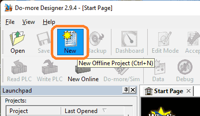 Select New to start a new project. This can also be selected from the main menu | New…
 We will select the Do-More Simulator as the project that we will be programming. Select OK.
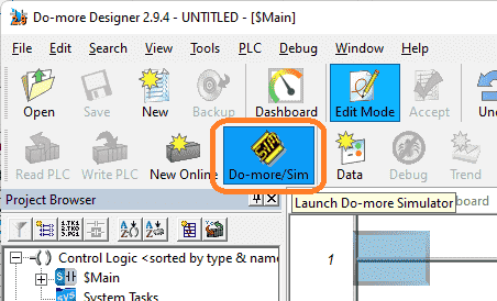 Edit mode is on by default when you start a project. This will allow you to program the PLC. Select Do-More/Sim to start the simulator.
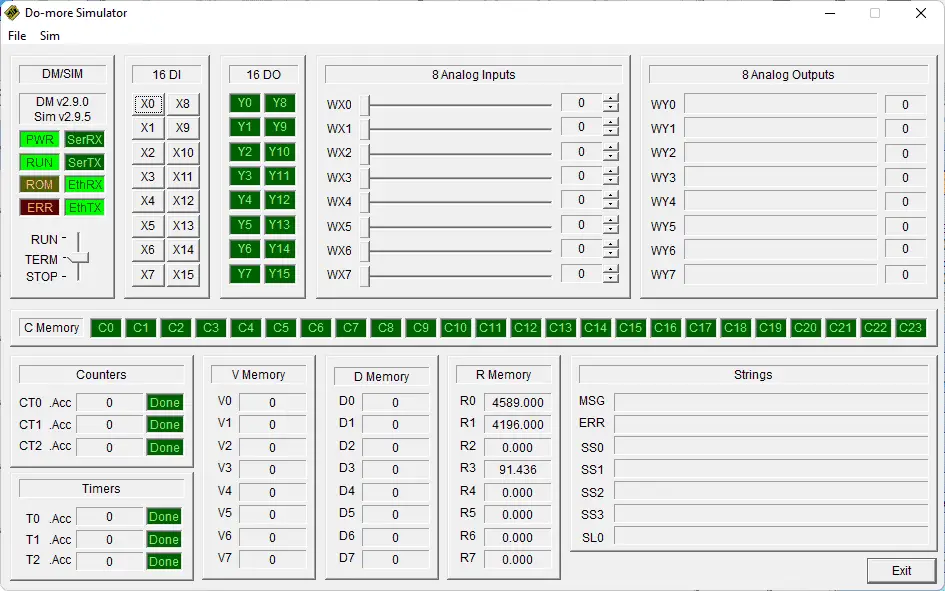 Here is the Do-More Simulator. Treat this as separate hardware in which you have to establish online communication and transfer/monitor the program.
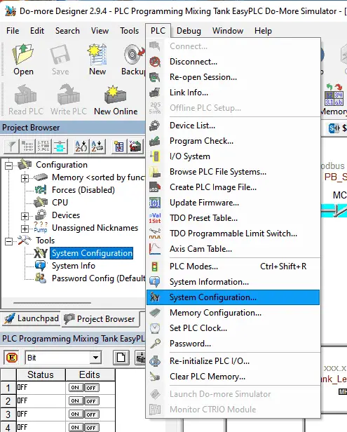 Select the system configuration under PLC on the main menu. You can also call this up by selecting system configuration under the tools menu in the project browser window.
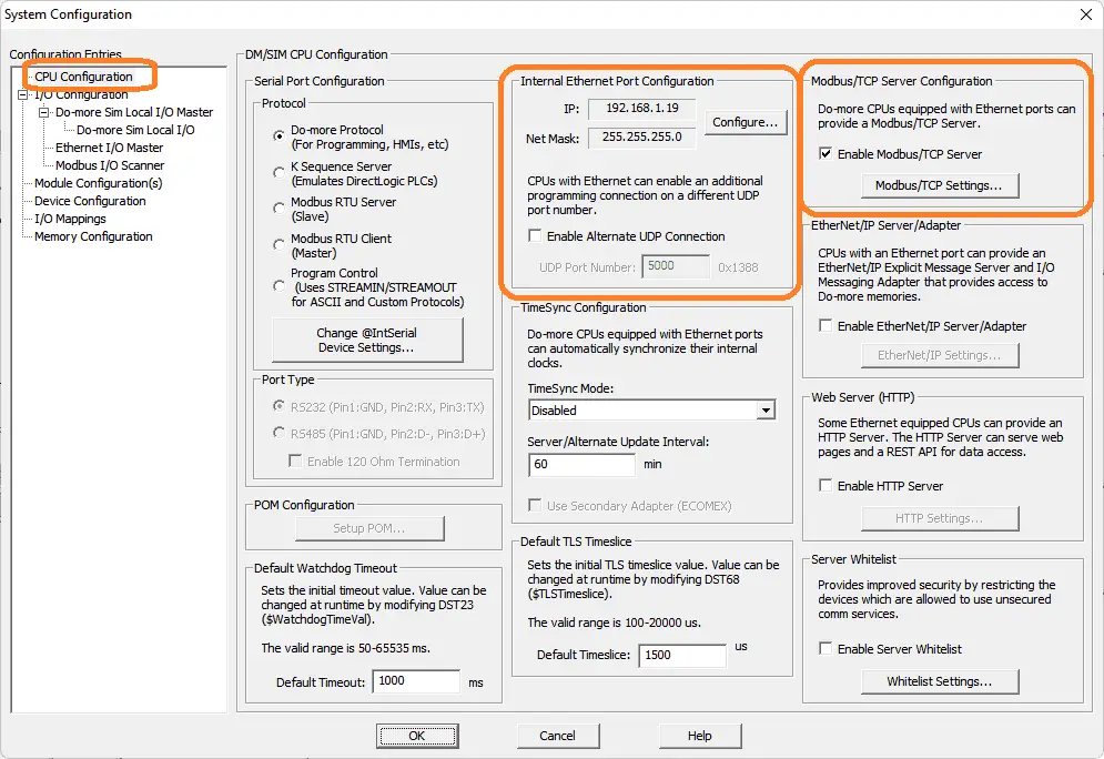 Select the configure button under the internal Ethernet port configuration.
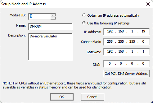 We will use a static IP address for the Ethernet port. Here are our settings for the Ethernet port. Select OK.
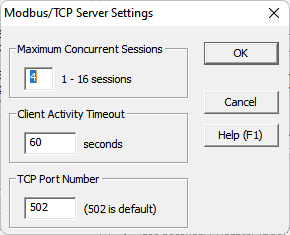 In the system configuration window, select Modbus TCP settings and ensure that the Enable Modbus / TCP Server is selected. This is on by default with port 502 as the default number. Everything is left as the default. We can change some of these settings if communication can not be established reliably. Our PLC is now set up as a Modbus TCP Server to the EasyPLC Modbus TCP Client. Make a note of the static IP address that we are using for the Do-More PLC. This will be used later to connect to the EasyPLC machine simulator.
Ladder Logic Program
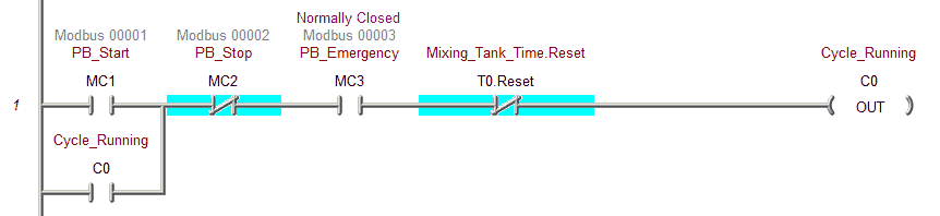 The first rung of the program will control the cycle start and stop. C0 is the output address for this start-stop circuit. You can see that the stop push button, emergency stop, or timer reset will stop the cycle. Only the start pushbutton will start the cycle.
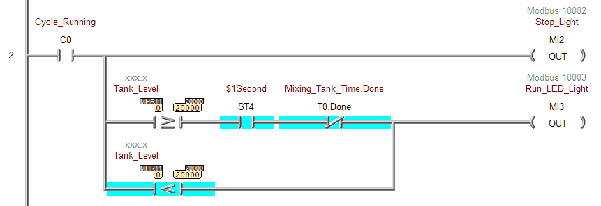 Rung 2 will control the stop light and run the LED light. If the cycle has started then the stop light will be on. This indicates to the operator the way to stop the cycle. If the cycle has started and the volume is less than 2000 then the run LED light is on. This light will flash when the volume is greater than 2000 and the timer has not been completed.
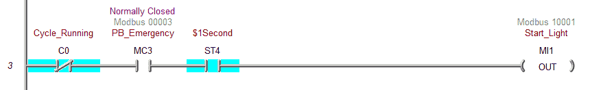 Rung 3 controls the start light. It will flash when the cycle has not started and the emergency stop is normal.
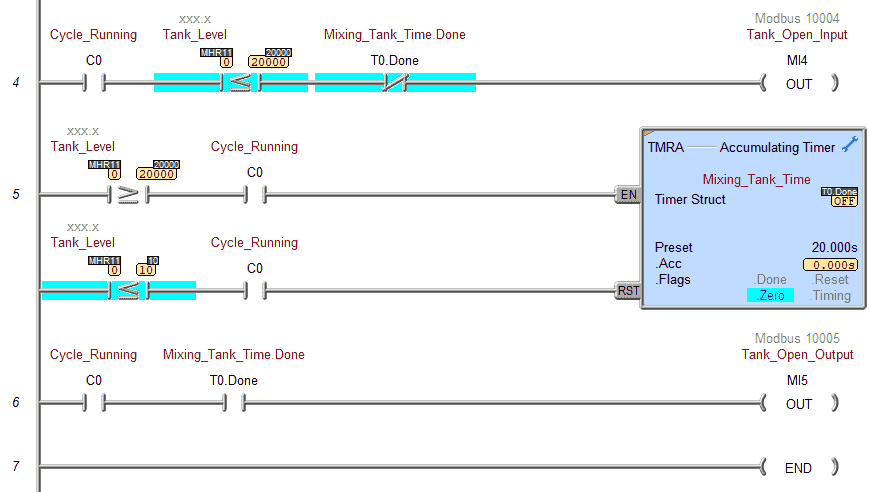 The tank open input will be on when the cycle has started and the volume is less than 2000 liters and the timer has not been completed. When the timer completes, this prevents the tank from continually filling when it is below the 2000 level.
An accumulative timer is used with a set value of 20 seconds. When the tank level is greater than 2000 and the cycle is running the timer will be enabled. The timer reset happens when the tank level is less than 10 liters and the cycle is running. This timer is memory retentive. If the cycle is stopped, the present value is remembered, so the cycle will continue when it starts again.
The tank open output is on when the timer has timed out (Done) and the cycle is on. The timer reset will control when this tank output will then turn off.
Our ladder logic program is complete. Download the program to the Do-More Simulator PLC. Ensure that the controller is in run mode. We can now move on to our fifth step. Watch the video below to see this Do-More PLC program in action
Test the program: (Step 5 – PLC Programming Mixing Tank)
We will be using Modbus TCP on our Do-More PLC Simulator to communicate to the EasyPLC Machine Simulator.
We currently have our mixing tank in start mode.
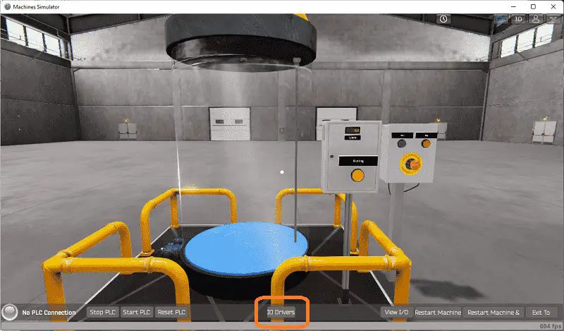 The status of the machine simulator will be at the bottom of the screen. Currently, we have no PLC connected. Select IO Drivers on the bottom middle of the screen.
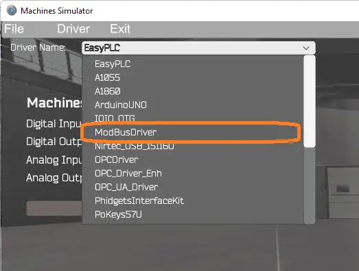 The EasyPLC driver is selected by default. Select the down arrow on the driver’s name. Under the driver pull-down menu, select “ModBusDriver”. This driver will communicate Modbus TCP (Ethernet) and Modbus RTU (Serial).
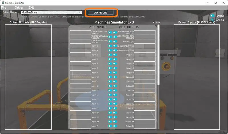 Select the configure button.
 We can now enter the information for our Modbus driver. Select TCP/IP. This really means the Ethernet port on the computer will communicate to the PLC.
The digital inputs from MS to the Do-More PLC will be MC1 to MC3. This will start at address 0 due to the offset of 1 and the first input is not used. Digital outputs from MS to the Do-More PLC will be MI1 to MI6. This will start at address 1 due to the offset of 1 and the first input is not used. Analog inputs start at MHR1. The analog output for our level sensor will be MHR11. The analog scale factor is set to 10. This means that the value of 20000 is really 2000.0. Modbus communication will not handle decimal values well. Select the OK button.
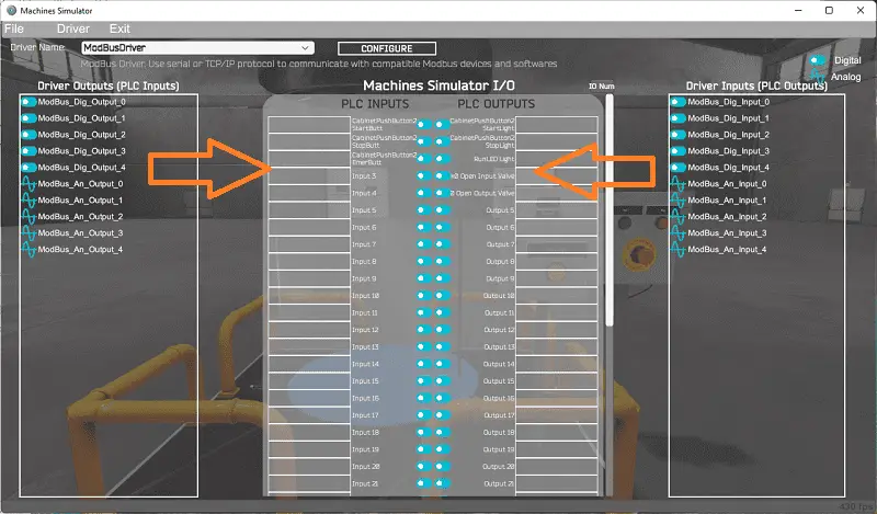 You will now see the inputs and outputs that we have specified for the Modbus driver. We can now manually assign the driver outputs to the PLC inputs and the driver inputs to the PLC outputs. However, the automatic assignment works well and will save you time.
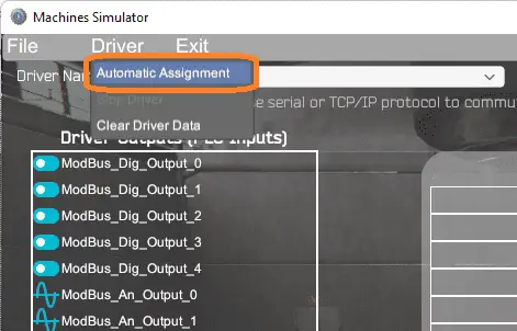 Select Automatic Assignment from the driver option in the main menu.
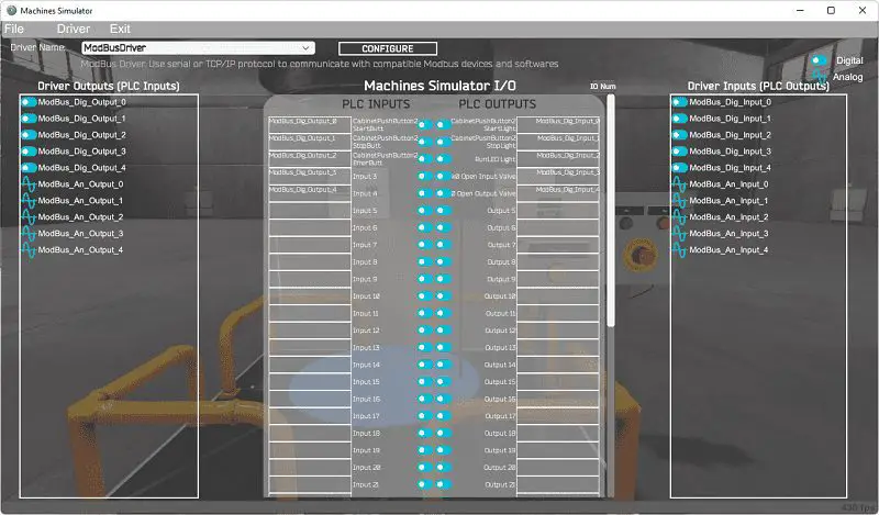 This will automatically assign the PLC IO to the Machine Simulator IO.
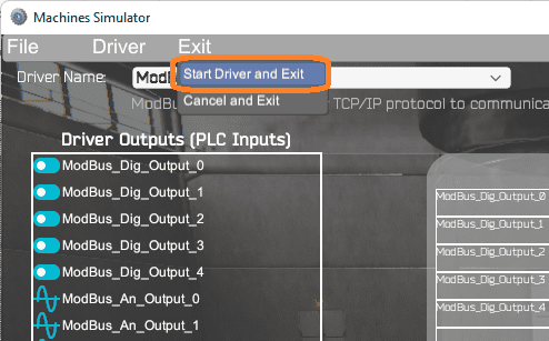 Select start driver and exit from the main menu.
 You will see on the bottom left side of the window that the driver is communicating to the PLC by the green light. Select view IO to see the input and output status of the machine simulator.
 Ensure that the PLC is in run mode. We can see the operation of our EasyPLC mixing tank.
Using the Data View window of the Do-More Designer programming software we can watch the inputs and output operations. We can also monitor the ladder logic. Watch the video below to see this operation.
If your program works correctly, it’s time to move on. If not, you’ll need to debug. This can be as simple as re-downloading and re-uploading your program or as complicated as re-designing your logic altogether. To learn more about developing logic check out our tutorials on the five steps to PLC program development. When using EasyPLC, debugging is easily done with no damage to any equipment. You may have to modify your logic several times before you get everything right! That’s okay—it’s all part of learning. After all: trial and error are often easier said than done!
You can practice your modification and debug by modifying the mixing tank in the following way:
– Add a cycle counter to track the number of cycles completed.
– Cycle three times when the start push button is pressed.
Let me know how you make out in the comments below!
Download the Do-More PLC sample program and EasyPLC Mixing Tank here.
Watch the video below to see the five steps of program development applied to the mixing tank. The machine simulator is one of the best applications to help you learn PLC programming.
EasyPLC Software Suite is a complete PLC, HMI, and Machine Simulator package. This PLC learning package includes the following:
Easy PLC – PLC Simulation allows programming in Ladder, Grafcet, Logic Blocks, or Script.
HMI System – Easily create a visual human-machine interface (HMI)
Machine Simulator – A virtual 3D world with real-time graphics and physical properties. PLC programs can be tested using EasyPLC or through other interfaces. (Modbus RTU, TCP, etc.)
Machine Simulator Lite – Designed to run on Android Devices.
Machine Simulator VR – Virtual Reality comes to life so you can test, train or practice your PLC programming.
Purchase your copy of this learning package for less than USD 75 for a single computer install or less than USD 100 to allow different computers.
Receive 10% off the price by typing in ACC in the comment section when you order. http://www.nirtec.com/index.php/purchase-price/
Learn PLC programming the easy way. Invest in yourself today.
Watch on YouTube: PLC Programming – Mixing Tank
If you have any questions or need further information, please contact me.
Thank you,
Garry
If you’re like most of my readers, you’re committed to learning about technology. Numbering systems used in PLCs are not challenging to learn and understand. We will walk through the numbering systems used in PLCs. This includes Bits, decimals, Hexadecimal, ASCII, and Floating points.
To get this free article, subscribe to my free email newsletter.
Use the information to inform other people how numbering systems work. Sign up now.

The ‘Robust Data Logging for Free’ eBook is also available for free download. The link is included when you subscribe to ACC Automation.