PID Loop (PID) Instruction (Auto Tuning) – Productivity 1000 PLC
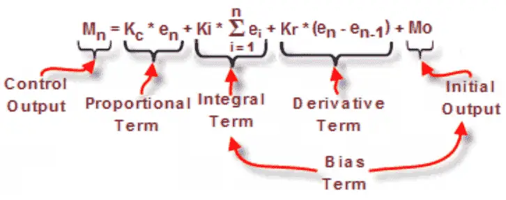
A Proportional-Integral-Derivative algorithm is a generic Control Loop feedback formula widely used in industrial control systems. A PID algorithm attempts to correct the Error between a measured process variable and the desired setpoint by calculating and then outputting a corrective action that can adjust the process accordingly and rapidly, to keep the Error to a minimum.
The following links will explain the PID instruction.
https://www.csimn.com/CSI_pages/PIDforDummies.html
http://www.ni.com/white-paper/3782/en/
https://en.wikipedia.org/wiki/PID_controller
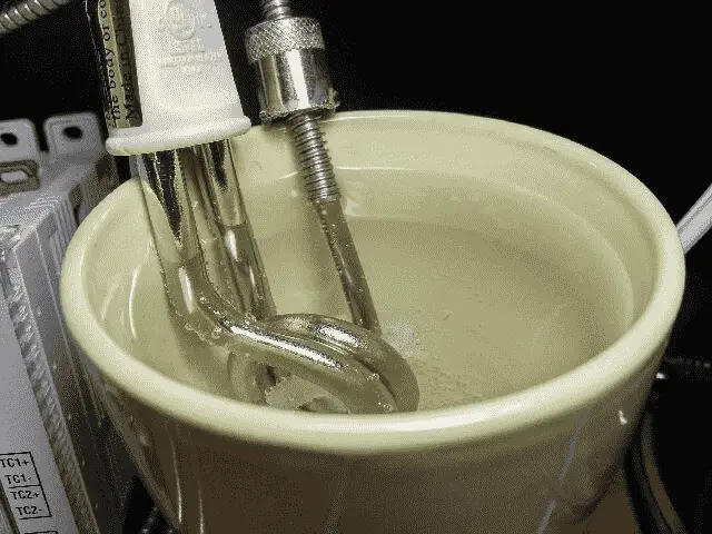
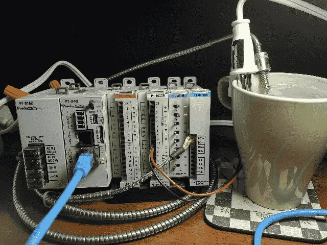
We will be using an immersion heater in a cup of water to keep the temperature at a constant value. Using the Productivity Suite software we will perform an autotune on our PID instruction.
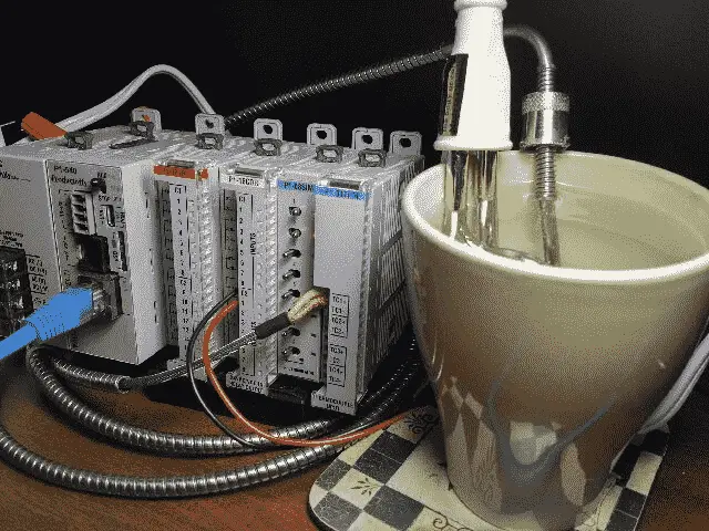
Our immersion heater will be controlled through a relay using time proportional control from our PID output. Let’s get started.
Previously in this Productivity 1000 series PLC, we have discussed:
System Hardware – Video
Installing the Software – Video
Establishing Communication – Video
First Program – Video
Documenting the Program – Video
Monitoring and Testing the Program – Video
Online Editing and Debug Mode – Video
Numbering Systems and Tag Database – Video
Contact and Coil Instructions – Video
Timer Instructions – Video
Counter Instructions – Video
Math Instructions – Video
Data Handling Instructions Part 1 – Video
Data Handling Instructions Part 2 – Video
Array Functions Part 1 – Video
Array Functions Part 2 – Video
Array Functions Part 3 – Video
Program Control – Video
Drum Sequencer Instructions – Video
Data Logger – Video
Web Server – Video
Modbus RTU Serial Communication – Video
Modbus TCP Ethernet Communication – Video
Firmware Update – Video
AdvancedHMI Modbus TCP Ethernet Communication – Video
Email and Text Communication – Video
Thermocouple Card (Feedback) – Productivity 1000 PLC (P1000)
We are using a P1-04THM thermocouple card to read our temperature in degrees Celsius.
Under the Setup in the main menu, select Hardware Config.
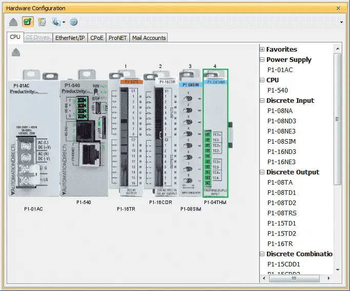
Double click on the card to call up the P1-04THM window.
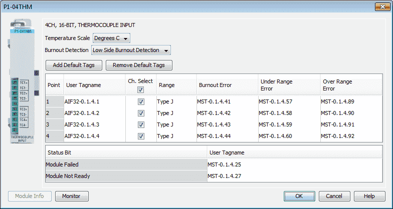
Our temperature scale will be set for Degrees C. The first point input will be used with a J type thermocouple. We will leave the default User Tagname for this point as AIF32-0.1.4.1.
Wiring – Productivity 1000 PLC (P1000)
As mentioned above we will wire our J type thermocouple into the first point of our P1-04THM card. We are using an immersion heater that is rated for 125W of power using 120VAC supply. DO-0.1.2.1 will be our relay output on our P1-16CDR card that will turn on and off our heater. This relay is wired in series with the heater. See the video below for the wiring and operation of our PID instruction in the Productivity 1000 PLC.
Creating our Ladder Diagram – Productivity 1000 PLC (P1000)
PID Loop Instruction
We will create a new task called PID to run every scan under Task Management.
Under the Instructions section, select PID Loop under the PID heading.
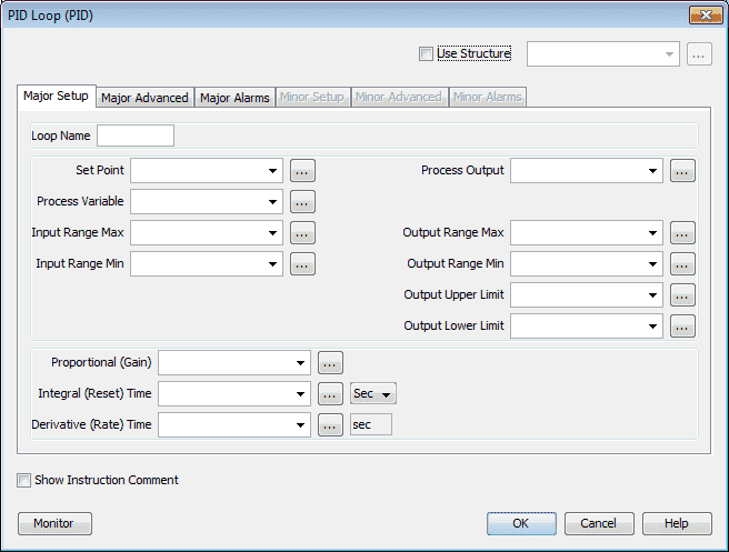
Click on Use Structure and call it PID1.
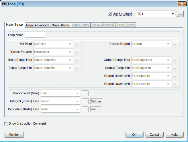
Uncheck the Use Structure. This will keep you from having to enter all of the fields manually.
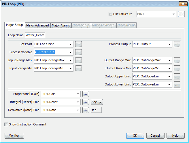
We will name the loop “Water_Heater”. Our process variable will be our thermocouple input. (AIF320.1.4.1)
Note: Our Set Point for our PID loop will be in the tag PID1.SetPoint. Most parameters required to configure a basic PID loop are located in this tab.
Click on the Major Advanced tab.
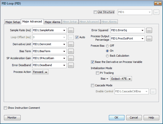
Here are all of the parameters set with tags. Common configuration parameters for more Advanced applications are located on this tab. Our process action will be left as the default forward. Click on the Major Alarms tab.
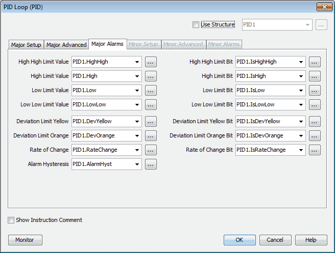
All of the limits, deviations and alarm information and bits are displayed. Hit OK.
Note: Minor tabs are only active when cascade mode is selected.
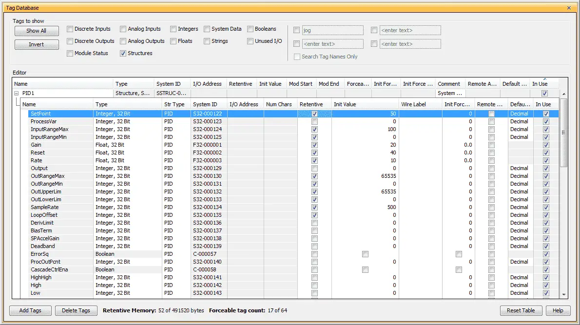
We will now set up our parameters in the Tag Database under the Structure for PID.
Our set point will be memory retentive with an initial value of 50 degrees C.
InputRangeMax is set at 100 degrees C and the InputRangeMin is set at 0 degrees C.
The Gain (P), Reset (I) and Rate (D) have been changed to a Float, 32Bit. This will allow the values to be more defined. They are also selected as memory retentive.
OutRangeMax is set for 65535. This is the maximum value for a 16-bit register. (FFFF) The OutRangeMin is set for 0. The OutUpperLimit and OutLowerLimit is set for the same values.
SampleRate is set for 500. This represents 500 ms or twice a second. Our PID loop values will be solved two times every second.
Our PID Loop instruction is just about complete.
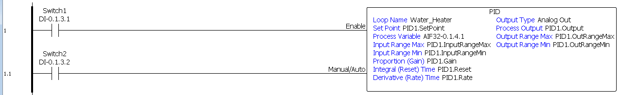
We will add Switch 1 to enable our PID instruction. Switch 2 when off will set the instruction to manual. When switch 2 is on the instruction will be automatic.
Time Proportional Control (Relay Cycle ) – Productivity 1000 PLC (P1000)
Time-proportional control will take our PID output and energize a relay to be on in our control period at the same ratio as the PID output. Our PID loop output will be a value between 0 and 65535.
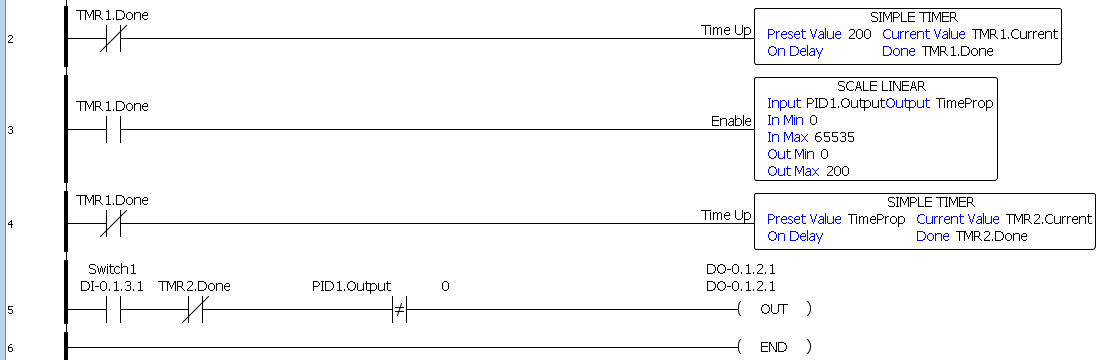
The first rung sets up a control period for our relay. In our case, we are using a 2-second timer as our control period.
Scale linear is used to scale our PID output (0 to 65535) to our control period (0-2.00 seconds)
TMR2 sets the amount of time that our relay will be ON for our control period.
Rung 4, line 5 contains the logic to turn on the relay for the proportion of the control period. PID1.Output not equal to 0 will ensure that the output will not chatter every time TMR1 resets.
Our ladder logic is now complete.
PID Tuning – Productivity 1000 PLC (P1000)
Once our program has been downloaded into the PLC, we can now tune our PID loop. Ensure that you are online with the controller and select PID Tuning under the Monitor and Debug heading in the Application Tools. Alternatively, you can use the main menu Tools | PID Tuning.
The PID loop must be enabled with our switch 1 and in manual mode (Switch 2 off) for tuning to take place.
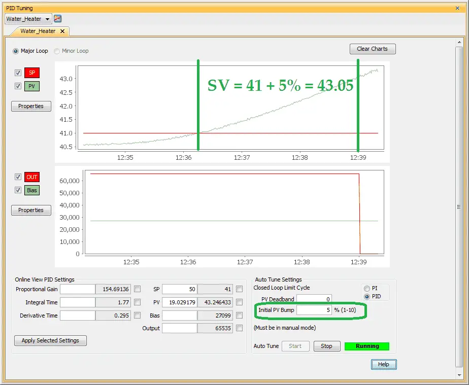
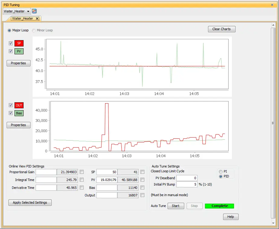
Call up our Water_Heater loop. You will see two graphs. The first graph is for SV (set value) and PV (present value). Graph two will show the OUT of the PID loop and Bias. Bias is the percentage Value that is added to the Output to stabilize the process control.
In the picture above we have started the auto-tune process. The initial PV Bump was set to 5%. This means that the SV will be increased from 41 to 43.05 before the output will turn off. You will see the indication of the process Running.
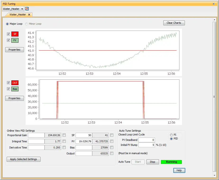
The Ziegler-Nichol Closed Loop Tuning method is used to drive the control output fully ON to drive the Process Variable (PV) above the configured Set Point (SP) then drive the control output fully OFF until the PV drops below the SP. It repeats this method for three complete cycles to accurately calculate the new P-I-D values for your process.
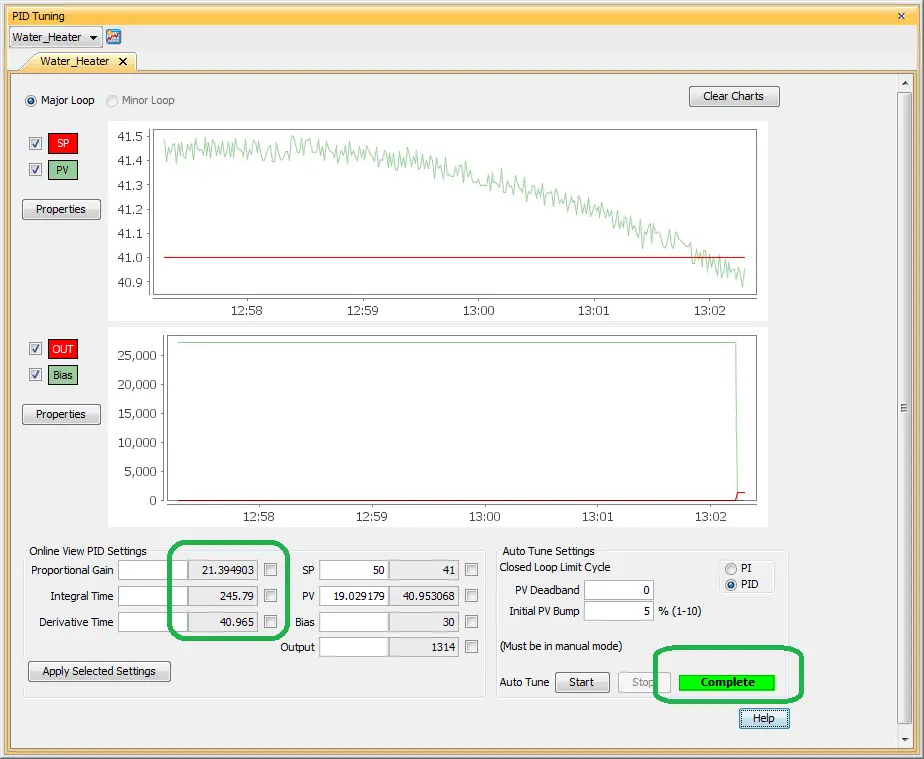
When auto-tuning has been completed there will be an indication showing Complete. The PID values will now be changed.
Placing our switch 2 on will put our PID Loop instruction in auto.
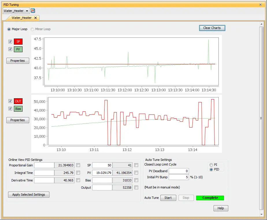
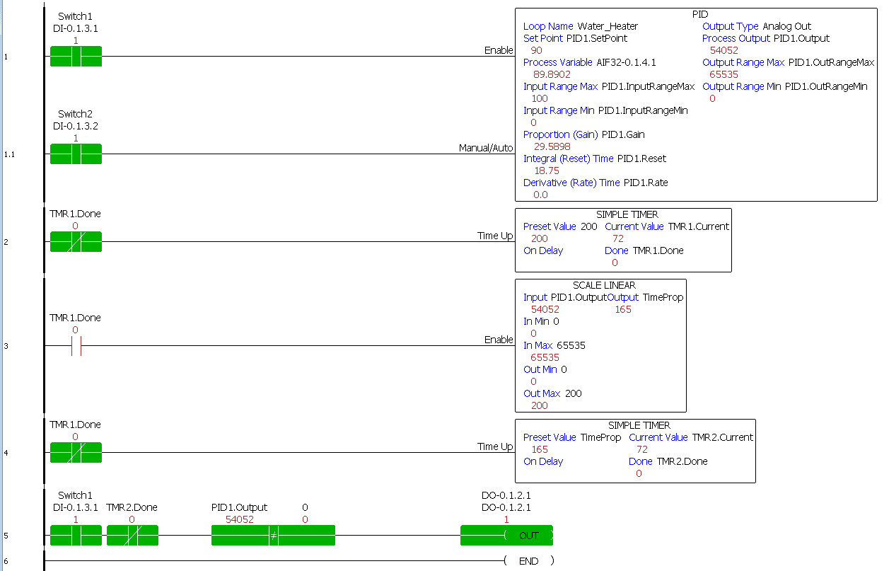
We can monitor the control that we have programmed and tuned.
Download the productivity 1000 PID instruction program here.
See the video below to watch our PID instruction (Auto Tuning) in action with our Productivity 1000 PLC.
Productivity 1000 Series PLC from Automation Direct
Overview Link (Additional Information on the Unit)
Configuration (Configure and purchase a system – BOM)
User Manual and Inserts (Installation and Setup Guides)
Productivity Suite Programming Software (Free Download Link)
This software contains all of the instruction sets and help files for the Productivity Series.
Next time we will look the ramp/soak PID instruction in the Productivity 1000 Series PLC.
Watch on YouTube: Productivity 1000 Series PLC PID Instruction (Auto Tuning)
If you have any questions or need further information please contact me.
Thank you,
Garry
If you’re like most of my readers, you’re committed to learning about technology. Numbering systems used in PLC’s are not difficult to learn and understand. We will walk through the numbering systems used in PLCs. This includes Bits, Decimal, Hexadecimal, ASCII and Floating Point.
To get this free article, subscribe to my free email newsletter.
Use the information to inform other people how numbering systems work. Sign up now.

The ‘Robust Data Logging for Free’ eBook is also available as a free download. The link is included when you subscribe to ACC Automation.