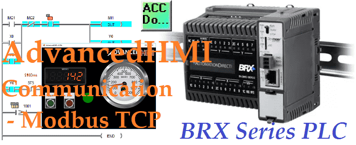
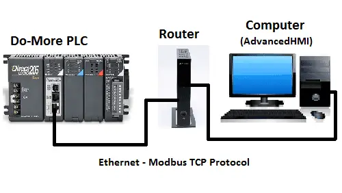
Modbus TCP will be used to connect AdvancedHMI to our BRX Do-More controller using Ethernet. Advanced HMI is a powerful, adaptable HMI/SCADA (Supervisory Control and Data Acquisition) development package that takes advantage of Visual Studio. There is no coding required and you can simply drag and drop items onto the page. The best thing is that the software is free. We will look at using AdvancedHMI with the BRX Do-More Series PLC.
Our sample BRX Do-More PLC program will display a digital panel meter and a gauge of a value in the PLC. Stop and start momentary pushbuttons on the HMI will allow this number to increase or stop. An indication will turn green when the number is increasing and red when it has stopped. The AdvancedHMI package will communicate Modbus TCP over Ethernet to the BRX Do-More PLC. We will be able to monitor our process via the AdvancedHMI window. Let’s get started. Watch on YouTube…
Previously in this BRX Do-More series PLC, we have discussed:
System Hardware – Video
Unboxing – Video
Installing the Software – Video
Establishing Communication – Video
Firmware Update – Video
Numbering Systems and Addressing – Video
First Program – Video
Monitoring and Testing the Program – Video
Online Editing and Debug Mode – Video
Timers – Video
Counters – Video
High-Speed IO – Video
Compare Instructions – Video
Math Instructions – Video
Program Control – Video
Shifting Instructions – Video
Drum Instruction – Video
Serial Communication – Modbus RTU to Solo Process Temperature Controller – Video
Data Logging – Video
Email – Text SMS Messaging Gmail – Video
Visual Studio Community 2017 – AdvancedHMI
A fully-featured, extensible, free IDE (Integrated Development Environment) for creating modern applications for Android, iOS, Windows, as well as web applications and cloud services. AdvancedHMI will run on this Visual Studio package. Download and install this from the link below.
Download Visual Studio Community 2017
https://www.visualstudio.com/downloads/
Here is a post that will guide you in installing visual studio.
https://accautomation.ca/create-a-plc-with-hmi-training-and-learning-environment-free/
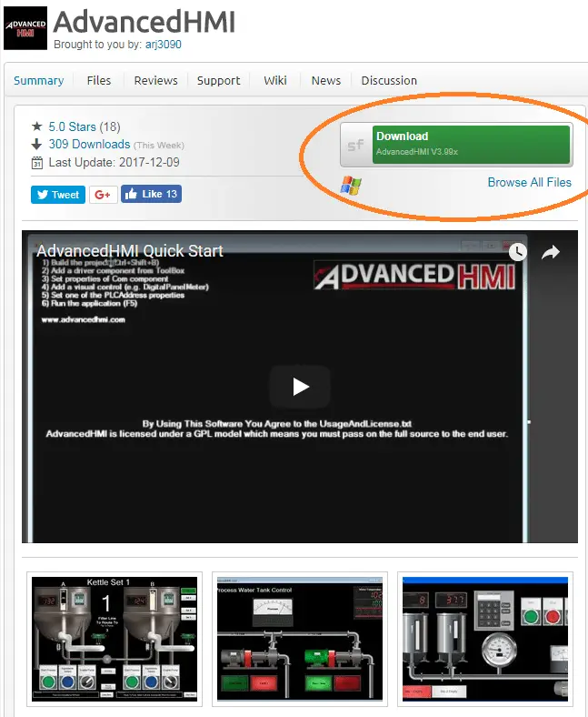
Download AdvancedHMI. The current version of the software is 3.99x.
https://sourceforge.net/projects/advancedhmi/
BRX Do-More Series PLC – Modbus Address Map
The following table shows the Coil/Register numbers and the associated BRX Do-More PLC address for Modbus.
| Coil/Register Numbers | Data Addresses | Type | Do-More PLC (BRX) | Table Name |
| 00001-09999 | 0000 to 270E | Read-Write | MC1 to MC1023 | Discrete Output Coils |
| 10001-19999 | 0000 to 270E | Read-Only | MI1 to MI1023 | Discrete Input Contacts |
| 30001-39999 | 0000 to 270E | Read-Only | MIR1 to MIR2047 | Analog Input Registers |
| 40001-49999 | 0000 to 270E | Read-Write | MHR1 to MHR2047 | Analog Output Holding Registers |
Note: The BRX Do-More Series PLC uses the Modbus area to communicate. This is because having direct access to the digital I/O can be dangerous when connected via Ethernet to the internet. Data must move in and out of this area via the PLC program.
BRX Do-More PLC Setup – AdvancedHMI
Program:
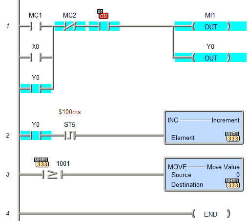
The following program will be used in the PLC to display and control our incrementing value in register V0.
MC1 is our start input from AdvancedHMI
MC2 is our stop input form AdvancedHMI
MI1 is our output to our AdvancedHMI indicating we are incrementing
MHR1 is our incrementing value. This value will increment from 0 to 1000 and then reset back to 0 again. This is done every 100 msec on the leading edge of the system bit.
BRX Do-More Configuration:
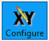
Hit the configuration button icon or from the main menu select PLC | System Configuration…
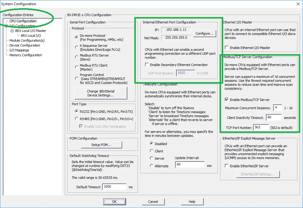
Under the CPU Configuration | Internal Ethernet Port Configuration make note of the IP address that the BRX Do-More PLC has set. In our case this is IP address 192.168.1.11.
Under the CPU Configuration | Modbus/TCP Server Configuration ensure that the following items are selected / set.
– Enable Modbus/TCP Server – this will ensure that AdvancedHMI will be able to communicate to the PLC.
– We will leave the following default parameters:
o Maximum Concurrent Sessions – 4
o Client Inactivity Timeout – 60 Seconds
o TCP Port Number – 502 (Modbus TCP Default)
Note: Modbus TCP (Ethernet) protocol is similar to Modbus RTU (Serial). Names of the Master (Client) and Slave (Server) can get confusing. Just remember that the two ‘S’ are the same thing. Slave / Server
AdvancedHMI Setup – Modbus TCP (Ethernet)
Now that we have our BRX Do-More PLC configured and programmed we will now look at the steps for our HMI display using AdvancedHMI.
Visual Studio must already be downloaded and installed on your computer from the link above.
When we downloaded the AdvancedHMI software it was one file called AdvancedHMIv399x.zip. If you right-click this file and select Extract All… , the files will be extracted.
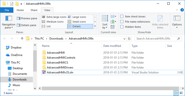
Double-clicking on the AdvancedHMIv35.sln file will call up this programming software.
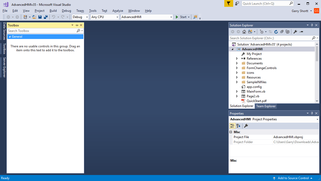
You will notice that the screen is blank. The toolbox is empty. Call up the main screen by clicking on the MainForm.vb under the Solution Explorer.
Notice that there are six steps listed on this page to help guide you to building your HMI project.
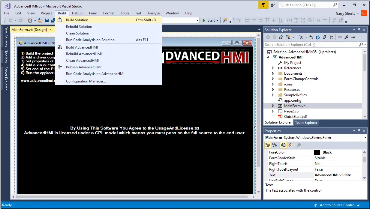
The first thing to do is build your solution. From the main menu select Build | Build Solution or use Ctrl + Shift + B.
Output window will automatically appear and display the process of the build. When completed, you can close the output window by the X in the upper right corner of the Output window.
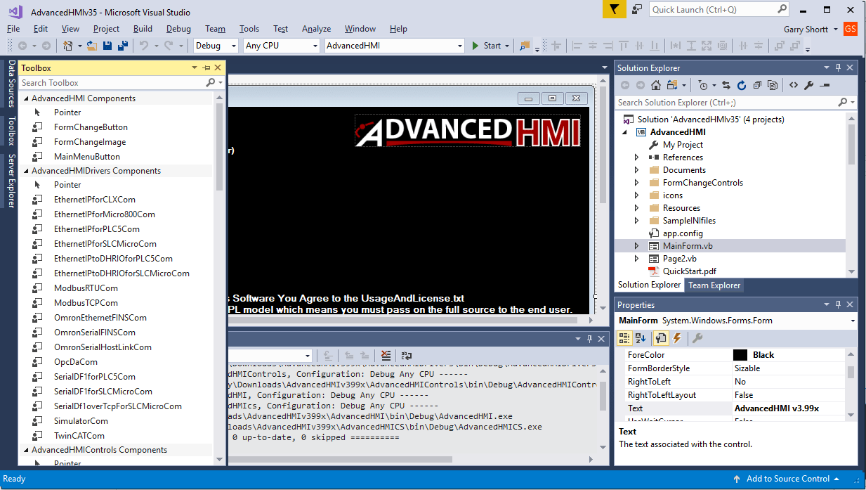
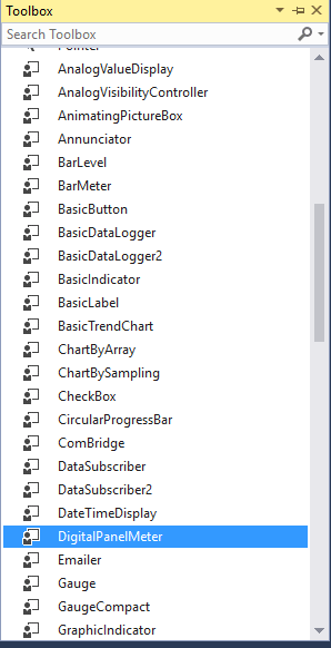
Your toolbox will now be populated with AdvancedHMI Drivers and Control components.
Add the ModbusTCPCom1 driver from the toolbox.
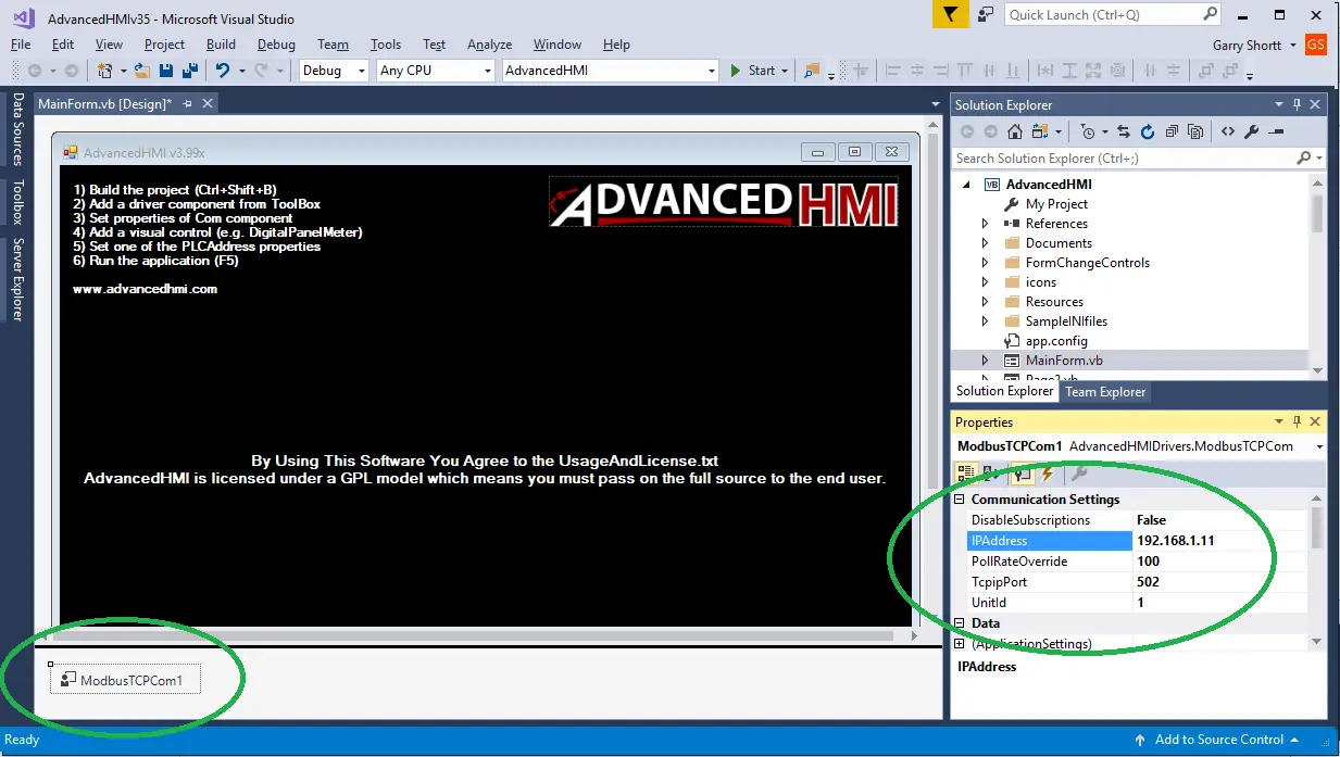
Clicking on the driver will display the properties for that component. We will set the following:
IP Address – 192.168.1.11 – Address of BRX Do-More PLC Ethernet Port
PollRateOverride – 100 (500 default) – This is the communication in msec that the program will communicate to the PLC.
Let’s now add a digital panel meter from the toolbox.
You select the control from the toolbox and place it on the main form. Here you can then resize the item by clicking and dragging the corner of the control.
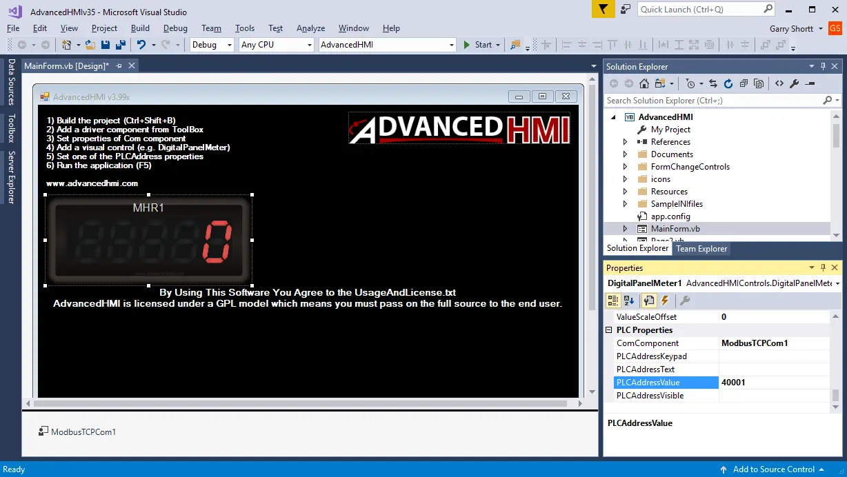
We will change the following properties on the DigitalPanelMeter.
BackColor – Black – This will get rid of the white around the edges (transparent is the default)
Text – MHR1 – This is the title on the digital panel meter.
PLCAddressValue – 40001 – This is the address that is mapped to MHR1 register.
Verify ComComponent – ModbusTCPCom1 – This should be the default after the communication device is added.
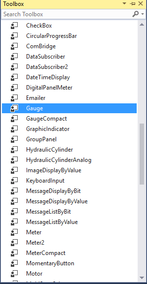
We will now add a gauge to our project from the toolbox.
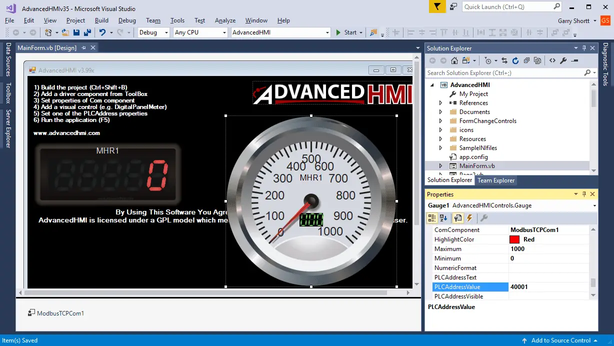
The following are the properties on the Gauge.
Text – MHR1 – This is the title on the gauge.
Maximum – 1000 – This is the maximum number that will be in register MHR1.
PLCAddressValue – 40001 – This is the address that is mapped to MHR1 register.
Verify ComComponent – ModbusTCPCom1 – This should be the default after the communication device is added.
Add two MomentaryButton’s onto the main screen from the toolbox.
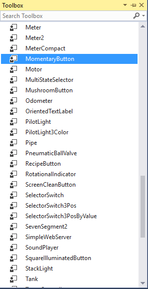
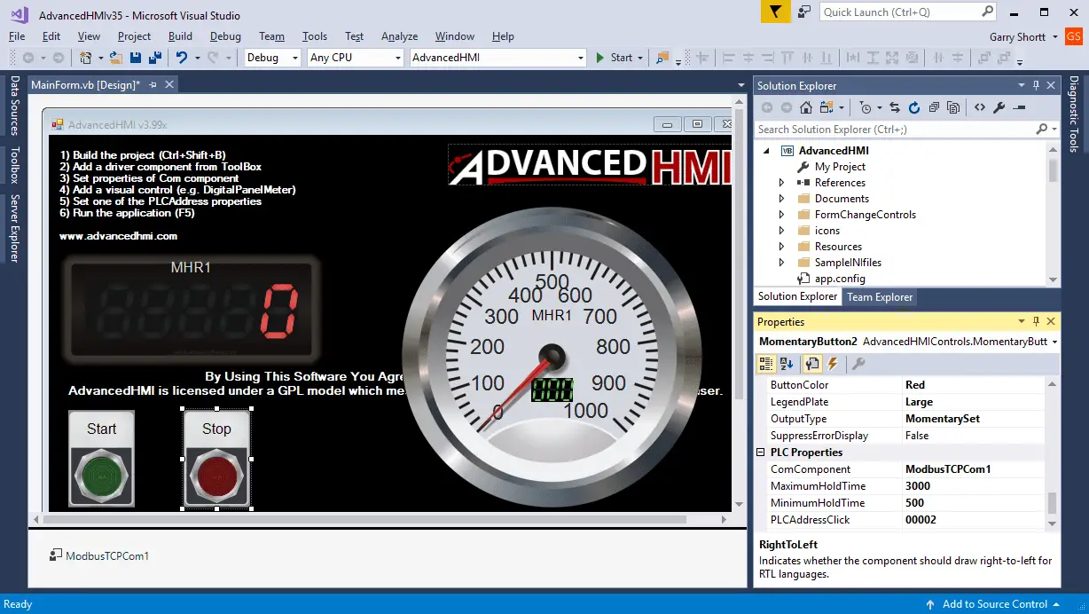
Here are the properties for the momentary buttons. (Pushbuttons)
MomentaryButton1
Text – Start – Name of the button
ButtonColor – Green – Colour of the button
PLCAddressClick – 00001 – This is the address for MC1 coil.
Verify ComComponent – ModbusTCPCom1
MomentaryButton2
Text – Stop – Name of the button
ButtonColor – Red – Colour of the button
PLCAddressClick – 00002 – This is the address for MC2 coil.
Verify ComComponent – ModbusTCPCom1
The last control component we will add to our AdvancedHMI screen is the BasicIndicator.
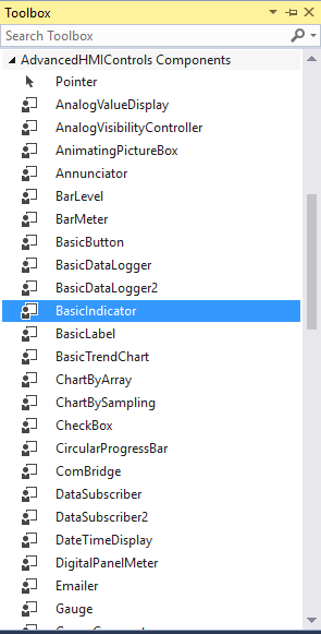
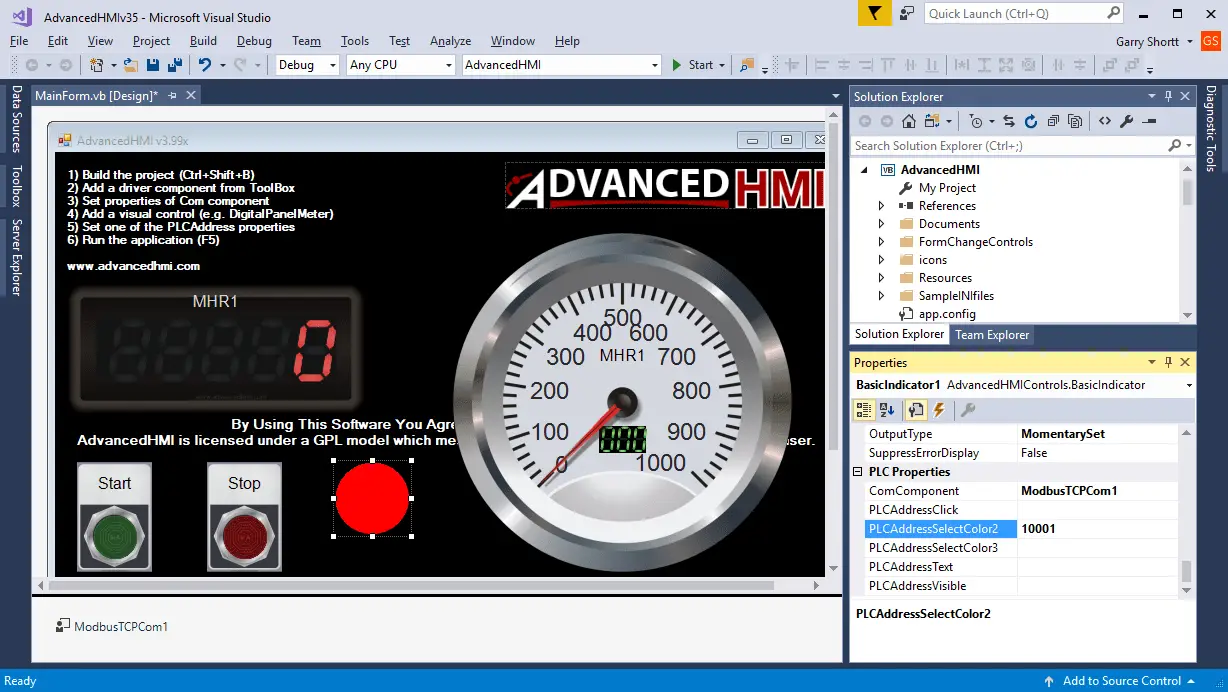
Here are the properties for the BasicIndicator.
Color1 – Red – This is the off condition
Text – ‘Blank’ – This is left blank so that no test is shown.
PLCAddressSelectColor2 – 10001 – This is the address for MI1 coil.
Verify ComComponent – ModbusTCPCom1
We now have our AdvancedHMI screen complete. Select the save icon or use the main menu | File | Save All to save our program.
To run the program, select the start button.
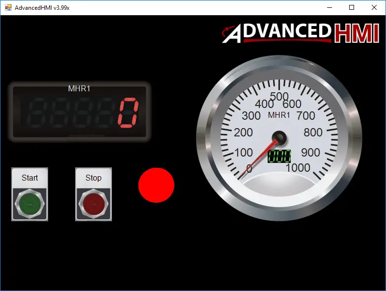
The following will show the screen upon starting:
Ensure that we can start our program by forcing the contact be X1 on in our logic above. We can then click the start momentary button on our screen to start the process.
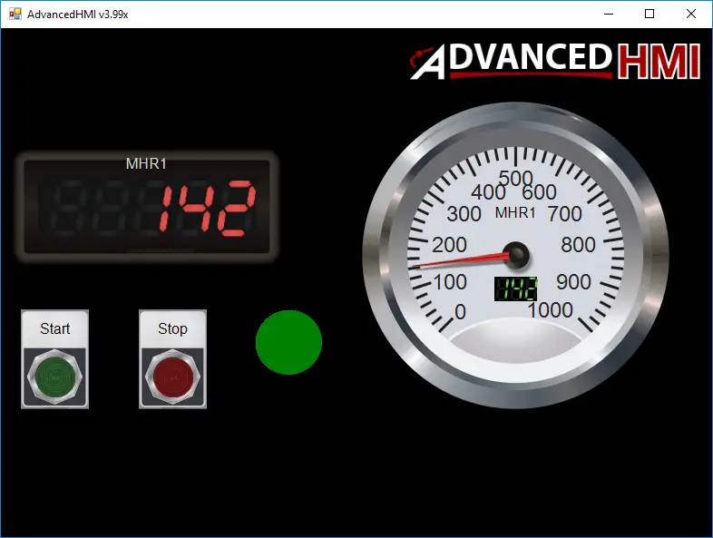
You will see the indication go from red to green when we start the incrementing of V0. The digital panel meter will display the value. The gauge will show you the value on the dial as well as the number in the center of it. Stop and Start can be used on the HMI screen to start and stop the incrementing of the value.
See the video below to watch how easy it is to create an AdvancedHMI screen.
You can download the program here.
Here are some posts that we have discussed AdvancedHMI:
https://accautomation.ca/click-plc-advancedhmi-communication/
https://accautomation.ca/omron-cp1h-advancedhmi-communication/
https://accautomation.ca/horner-xl4-modbus-tcp-advancedhmi-communication/
https://accautomation.ca/advancedhmi-to-solo-process-temperature-controller/
https://accautomation.ca/deploying-an-advancedhmi-project/
https://accautomation.ca/creating-a-hmi-login-screen-on-advancedhmi/
https://accautomation.ca/building-a-plc-program-that-you-can-be-proud-of-part-6/
BRX Do-More Series PLC from Automation Direct – Power to deliver
Overview Link (Configure and purchase a system)
Manuals and Product Inserts (Installation and Setup Instruction)
Do-More Designer Software v2.0.3 (Free Download Link) – The software will contain all of the instruction sets and help files for the BRX Do-More Series PLC.
Next time we will look at the analog cards in the BRX Do-More Series PLC.
Watch on YouTube: BRX Do-More PLC AdvancedHMI Communication – Modbus TCP
If you have any questions or need further information please contact me.
Thank you,
Garry
If you’re like most of my readers, you’re committed to learning about technology. Numbering systems used in PLC’s are not difficult to learn and understand. We will walk through the numbering systems used in PLCs. This includes Bits, Decimal, Hexadecimal, ASCII and Floating Point.
To get this free article, subscribe to my free email newsletter.
Use the information to inform other people how numbering systems work. Sign up now.

The ‘Robust Data Logging for Free’ eBook is also available as a free download. The link is included when you subscribe to ACC Automation.
Gary:
I’ve got the advanced HMI working with the domore simulator. But in domore designer, there seems to be no way to look at the modbus registers using the Data window or the memory window. They allow you to monitor the modbus registers (input/coils,holding registers) but their data is always zero. The modbus instructions do work (like read holding register), but the monitoring of the registers doesn’t appear to work. Have you noticed this?
Hi Mark,
I’ve responded to your question on YouTube.
https://youtu.be/1TjsdLwTKM0
Data View is a good tool in the Do-More Designer Software.
I’m glad you got it sorted out.
Thanks,
Garry