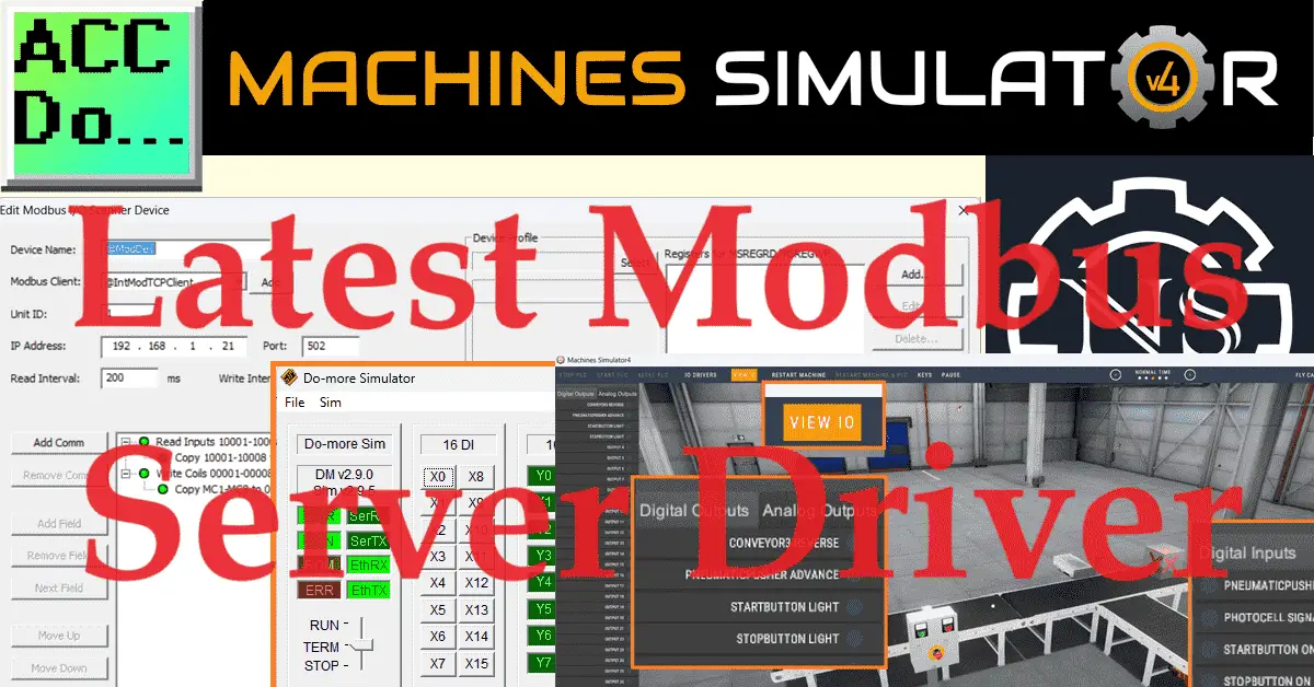
The latest Machine Simulator (EasyPLC) version, 4.1, now has a Modbus Server driver. This will allow the PLC or other controlling device to be the Client in the Modbus network. Machine simulators play a crucial role in industrial automation as they allow you to replicate real-world scenarios and test the functionality of different machines in a virtual environment. This helps identify and resolve potential issues before they occur in the production environment, saving time and resources.
Modbus server drivers are essential in industrial automation because they enable communication between various devices in a Modbus network. This allows for the exchange of critical data between different components of the industrial system, facilitating the seamless operation of machinery and ensuring efficient productivity. We will use the Do-More Designer PLC Simulator Modbus Scanner to connect to the newest Modbus Server driver of the Machine Simulator. Modbus TCP (Ethernet) will be used. Let’s get started. Learn PLC programming the easy way. See below for a 10% discount on this cost-effective learning tool. Invest in yourself today.
Previously, we have done the following:
Easy PLC Installing the Software – Video
EasyPLC Software Suite – Quick Start – Video
Click PLC – Easy Transfer Line Programming – Video
Productivity PLC Simulator – Chain Conveyor MS – Video
Do-More PLC – EasyPLC Box Selection Program – Video
Click PLC EasyPLC Gantry Simulator – Video
Click PLC Simple Conveyor EasyPLC – Video
EasyPLC Paint Line Bit Shift – BRX Do-More PLC – Video
Click PLC – EasyPLC PLC Mixer Programming – Video
Click PLC EasyPLC Warehouse Stacker Example – Video
– Operation Video
EasyPLC Machine Simulator Productivity PLC Robotic Cell – Video
EasyPLC Simulator Robotic Cell Click PLC – Video
Palletizing Conveyor Programming Do-More PLC – Video
Palletizing Conveyor Programming – Click PLC – Video
Product Quality Verification! Do-More PLC Sequencer – Video
Revolutionize Learning PLCs with Pallet 3D Sim! – Video
Robot Packing PLC Program Development – Video
Box Dumper Easily Learn PLC Programming – Video
Innovative Solution for Mixing Ink and Bottling – Video
Benchwork 1 Do-More Practice PLC Programming – Video
LS Electric XGB PLC Easy Transfer Program – Video
Do-More PLC Automatic Robot Packing Machine – Video
Understanding Machine Simulator Modbus Server Driver
A Modbus server driver is a software component that allows a device or system to communicate using the Modbus protocol as a server. The Modbus protocol is developed to establish communication between industrial electronic devices.
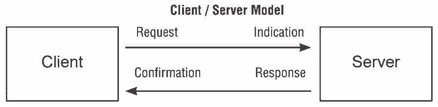
Modbus Request – the message sent on the network by the Client to initiate a transaction
Modbus Confirmation – the Response Message received on the Client side
Modbus Indication – the Request message received on the Server side
Modbus Response – the Response message sent by the Server
In the context of a server driver, the software can respond to requests and provide data to client devices that adhere to the Modbus protocol. This allows for exchanging information and control commands between different devices within a network. Typically, the Modbus server driver handles the communication and data exchange, ensuring that devices can effectively communicate and share data.
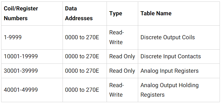
Modbus memory is divided into four different areas. Discrete output coils and discrete input contacts deal with bit logic. This means that they are either on or off (1/0). Analog input registers and analog output holding registers are 16-bit words. The interpretation of this information in the word register depends on the Modbus client requesting the information.
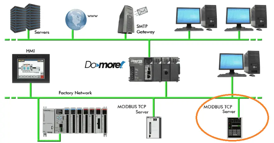
Every Modbus server on the network will have these four available memory locations to read or write information. Please reference the manuals of your Modbus server to see how your device uses this memory.
In the Machine Simulator, the Modbus Server Driver allows you to choose the Modbus memory area for the digital inputs and outputs and analog inputs and outputs.
Setting up the Machine Simulator Modbus Server Driver
We will use a prebuilt scene in the machine simulator or MS. Start the Machine simulator and select the “Machines” icon on the top menu.
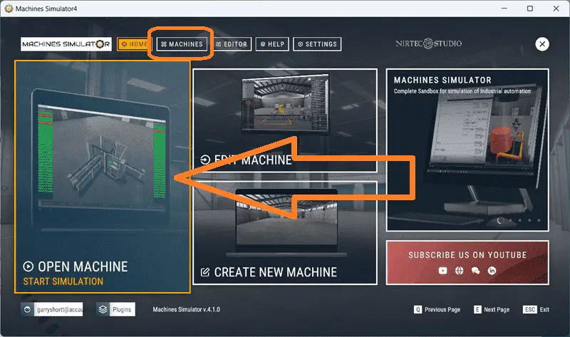
You can also select the “Open Machine – Start Simulation” on the main page.
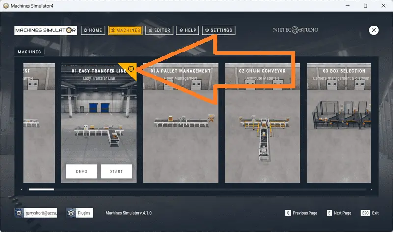
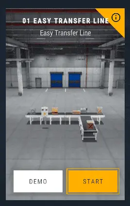
All of the prebuilt machines will now be displayed. These have been programmed, so you can immediately start learning with this package. We will be using the “01 Easy Transfer Line”. Selections will be displayed as you move your mouse over the machine icon. Select the exclamation point in the upper right corner.
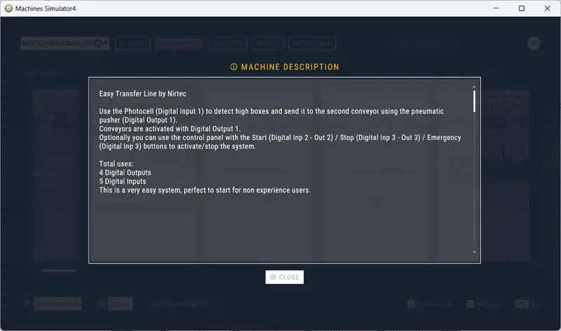
This will display the machine description of what you need to program. Select close. The “Demo” mode will show you the workings of the machine. It will demonstrate how the machine is to function. Select “Start”.
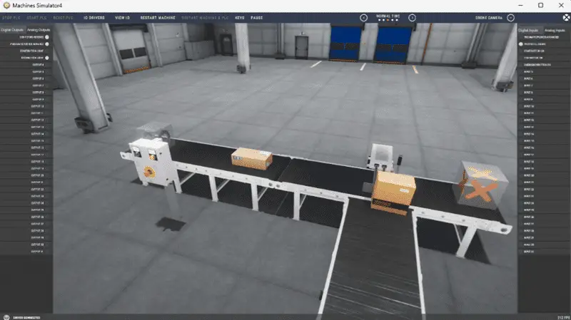
The machine simulator will now load the easy transfer line.
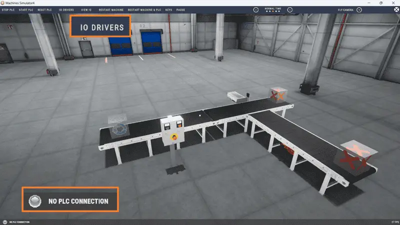
In the bottom left corner, you will see that we have “No PLC Connection”.
Select “I/O Drivers” on the top menu.
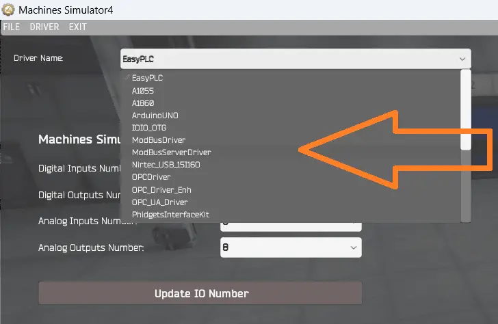
Under the “Driver Name,” you will see that EasyPLC is selected by default. Select “EasyPLC” to call up all of the Machine Simulator drivers. Select “ModbusServerDriver”.
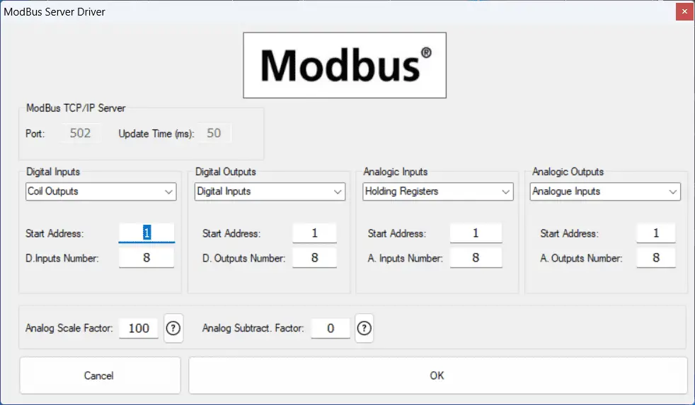
The Modbus server driver uses TCP/IP protocol on Ethernet to communicate with other Modbus devices and software.
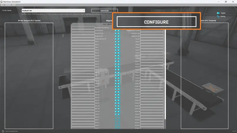
Select the “Configure” button.
We can now assign the machine Simulator to the four different Modbus memory areas. In our case, the PLC’s coil outputs will be MS’s digital inputs. The PLC digital inputs will be MS’s digital outputs. Although our machine does not use any analog inputs, we can still set this up. Modbus PLC holding registers will be used for the Analog inputs, and the PLC analog input registers will be MS’s analog outputs.
Analog scaling and subtraction factors are used in the machine simulator to represent negative numbers since Modbus analog is strictly a 16-bit word. Select OK.
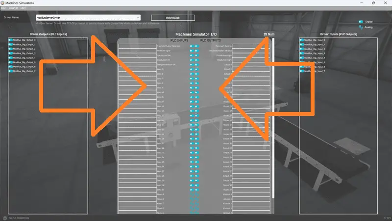
Our PLC inputs and outputs are now displayed. We can now assign the inputs and outputs to our Machine Simulator I/O. This can be done by clicking and dragging the PLC input to the Machine Simulator input and the PLC output to the Machine Simulator output. However, you can select “Automatic Assignment” from the driver menu.
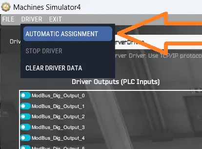
This will automatically assign the inputs and outputs in the order they appear, saving you time. Select automatic assignment.
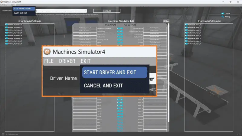
Under the exit menu, select “Start Driver and Exit”.
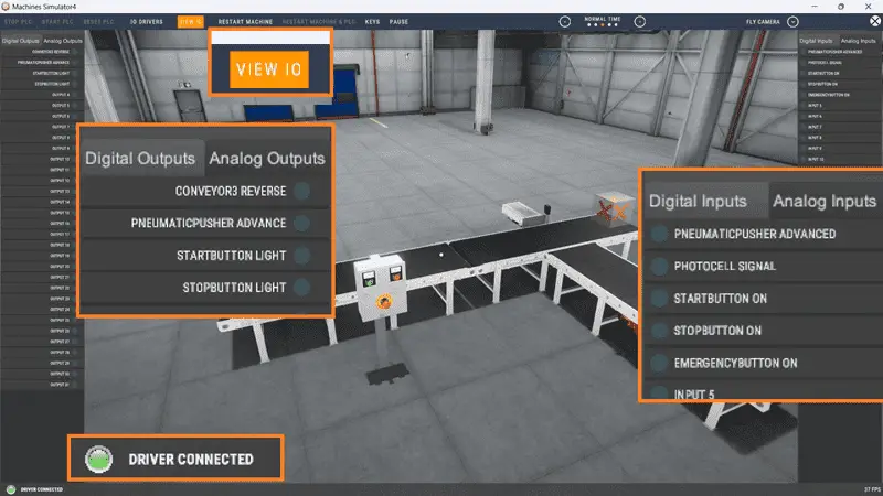
Our Easy Transfer Line is now ready for communication. This is shown by the green “Driver Connected” indication on the bottom left of the screen.
Select “View IO” to show the MS’s input and output status. Since this is a Modbus server setup, we can use multiple Modbus clients to connect to our Machine Simulator.
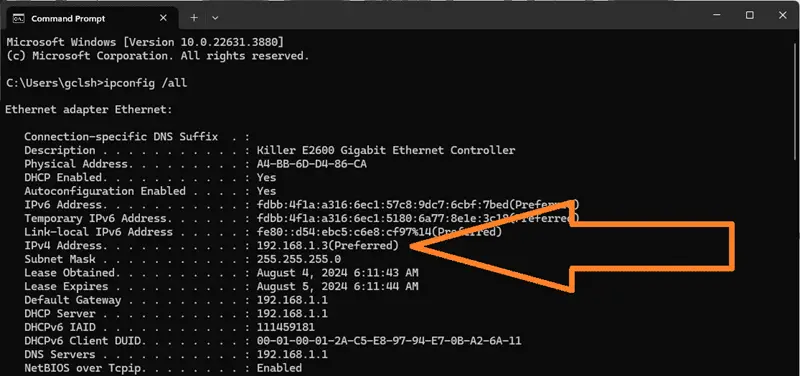
The IP address of our MS Easy Transfer Line will be the IP of the local computer running the software. If you are unsure, start a command prompt on your Windows computer. Type the command “ipconfig /all” and press enter.
You will now see the IP address listed. We will need to know this for the Modbus client device.
Setting up the Do-More PLC Simulator Modbus Scanner and Test
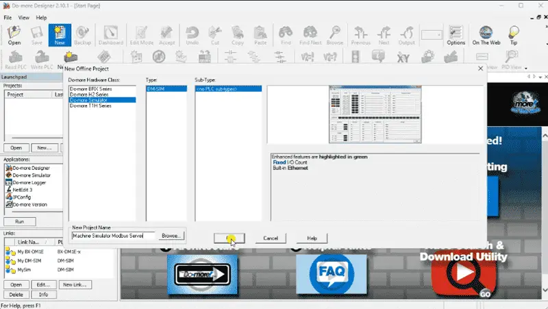
We will now set up and test the Modbus client for our network. Start the Do-More Designer Programming software. Select the new icon on the main menu to start a new offline program.
In the “New Offline Project” window, select D0-more simulator. Name the new project and select OK.
Remember to select the save icon on the main menu during our programming to ensure we do not lose any information while we work. Add an END statement to the ladder logic program.
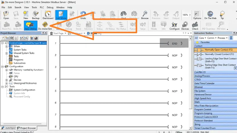
This will prevent errors while we test our Modbus client communication to the machine simulator Modbus server.
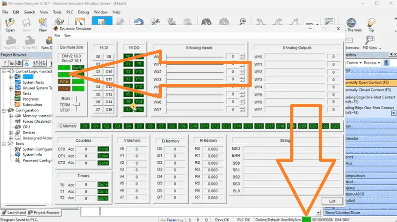
Since we are offline for the Do-More PLC simulator, we will not be able to see the IP address of the PLC. Select the Do-More Simulator icon on the main menu.
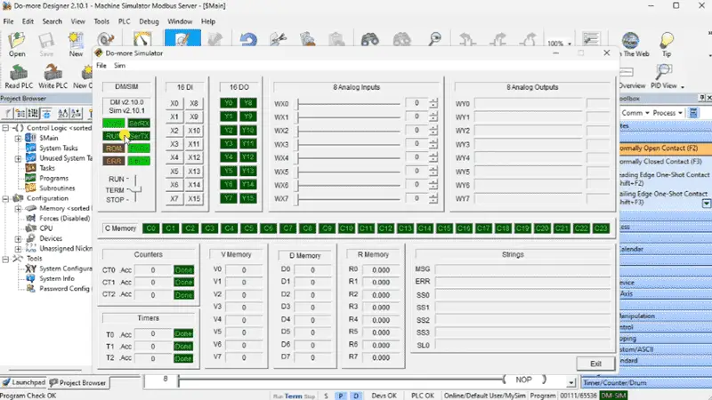
The Do-More simulator PLC will now be displayed. The mode of this PLC can be set by the switch on the simulator. We will leave this in terminal (TERM) mode to control the mode from the Do-More Designer software.
Returning to the programming software, select the Write PLC icon on the main menu.
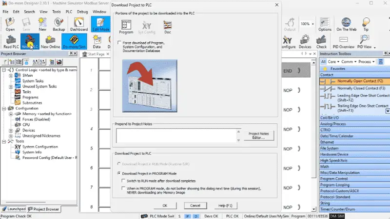
This transfers our ladder logic with the END statement and overwrites any existing program in the PLC simulator.
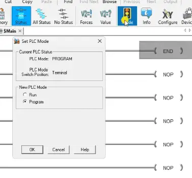
Change the PLC mode to run by selecting it from the Mode icon on the main menu of Do-More Designer. (Ctrl + Shift + R)
Select system configuration under tools in the project browser menu. You can also select system configuration under the main menu | PLC.
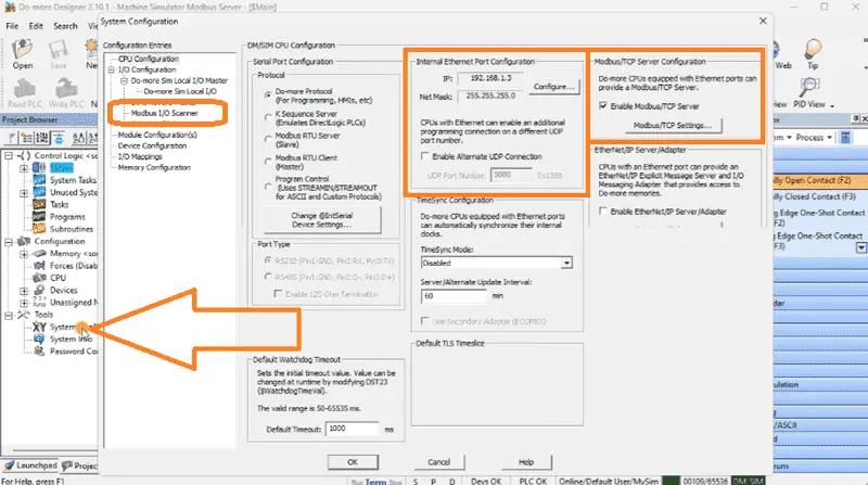
The CPU configuration is shown by default. You will see the IP address under the Internal Ethernet Port Configuration. Parameters for the Modbus Server are also shown. This is on by default, so our PLC can be both a client and server on the Modbus TCP network.
Select Modbus I/O Scanner under the I/O configuration on the left side of the System Configuration window.
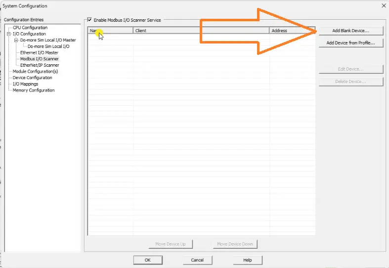
Select the Enable Modbus I/O Scanner Service. This will now allow you to select the Add blank device.
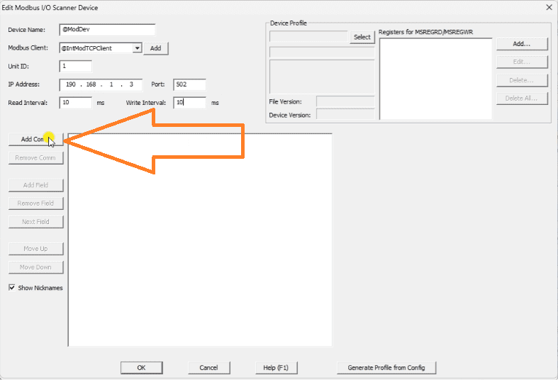
The edit Modbus I/O scanner device window will be displayed. A Modbus TCP Client will be selected as the default. We can now add the IP address and unit number of the server we wish to communicate with. The Machine Simulator Modbus Server driver uses machine unit number 1. Our read and write intervals will be set for 10 milliseconds each. This is 100 times per second that the update will happen for our Modbus information.
Select the Add Comm button.
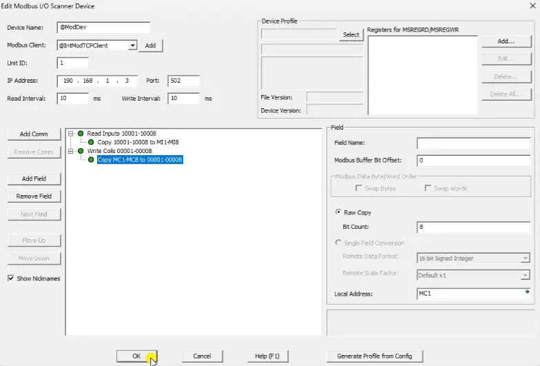
We will read 8 discrete inputs and store them in the field PLC memory location MI1 to MI8. We will also read 8 coils and store them in the field PLC memory location MC1 to MC8. Select OK to return to the system configuration menu. Select OK to return to the main Do-More designer software. A warning message will inform you that you have changed the system configuration, which must be transferred to the PLC. Select OK. Select the Write PLC icon on the main menu to transfer the program.
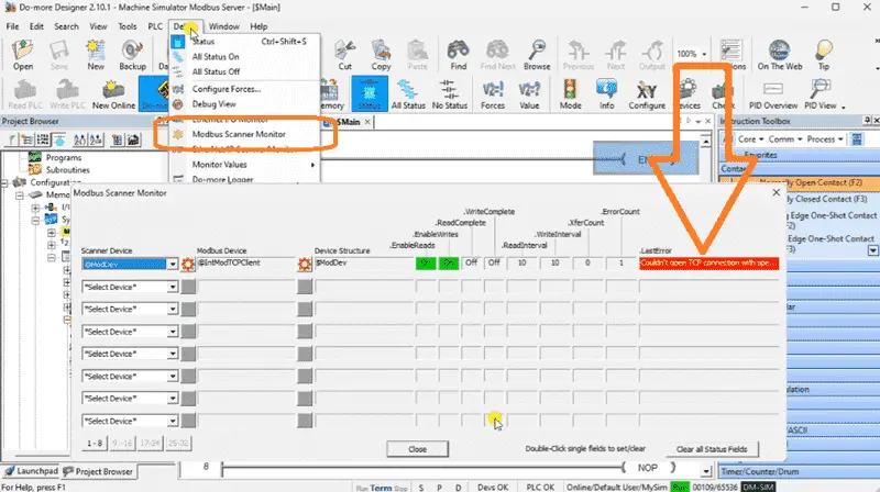
Select Modbus Device Scanner from the main menu | debug.
You will see that we have an error. This is displayed as “Couldn’t open TCP connection…”.
Return to the Modbus I/O Scanner in the system configuration menu. You will see that I set the IP address for the server incorrectly.
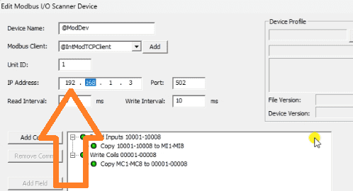
Correct the IP address. Transfer the program.
Call up the Modbus Scanner Monitor once again.
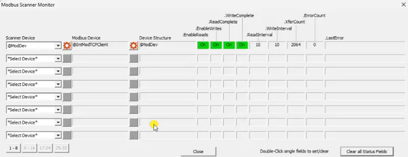
Select the Clear all Status Fields button. You will now see we have communications with our machine simulator Modbus server.
Let’s test the addresses now that we have communicated with the server. Select Data View | New from the main menu. (Ctrl + Shift + F3)
We can now monitor the inputs and outputs we read and write to the Modbus Server. To select the next variable in the data view list, use the control and enter keys.
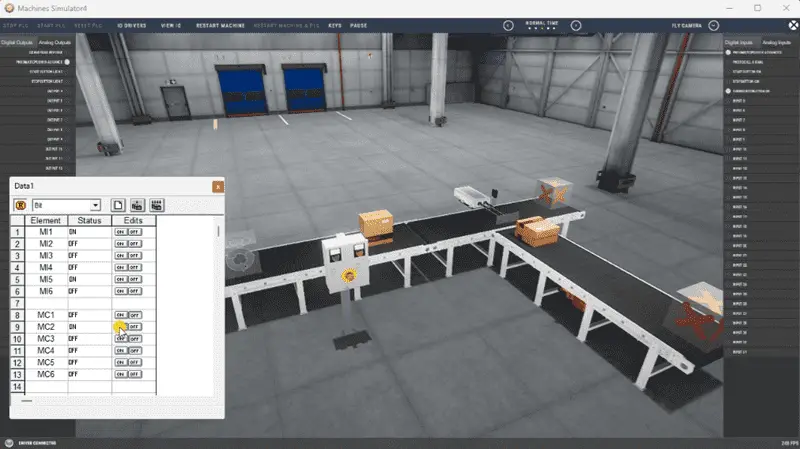
Viewing the machine simulator Easy Transfer Line, we can control and monitor the Modbus input and output bits.
Write the PLC Ladder Logic Code
We have covered the PLC program development in the “Streamline Programming Do-More EasyPLC Transfer” post. The PLC ladder logic program example followed the five steps to PLC program development.
Under the tools option in the main menu, select Documentation Editor. We can label the inputs and outputs for our ladder logic program.
Using online editing, we can enter our program.
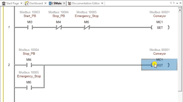
The first two lines will control the conveyor.
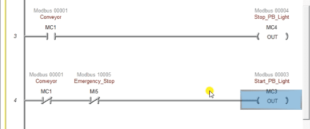
Rungs 3 and 4 will control the lights on the control panel of the machine simulator scene.
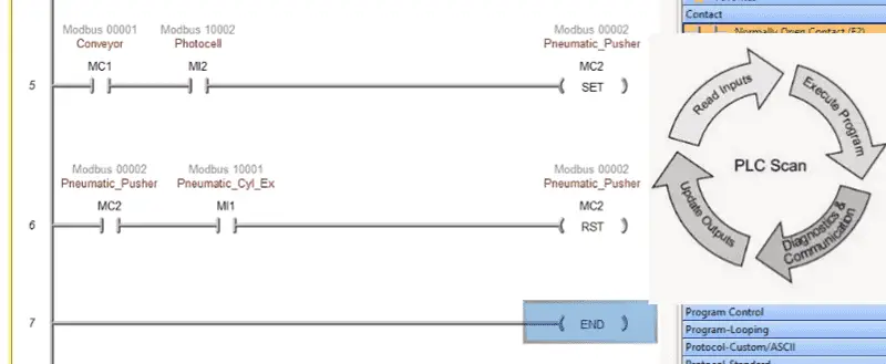
When the photocell sees the high boxes, the pneumatic pusher is activated. When the pusher reaches the extended position, it will reset the pneumatic pusher.
The END statement indicates that this is the end of the program and that the PLC scan continues.
Ensure that the Do-more Simulator is in RUN mode.
We can run the Machine Simulator Easy Transfer Line to ensure the ladder logic is correct.
One of the biggest advantages of the MS Modbus Server Driver is the ability to have multiple clients. This means that we can have multiple PLCs controlling the machine simulator scene.
This new MS Modbus Server Driver will allow you to practice PLC programming in new ways. Explore and take advantage of this new ability for industrial applications. Let me know your ideas in the comments below.
Download the PLC sample program here.
Watch the video below to see the five steps of program development applied to the Automatic Packing machine. The machine simulator is one of the best applications for learning PLC programming.
When using the Machine Simulator Software Suite, debugging is quickly done without damaging equipment. You may modify your logic several times before you get everything right! This is all part of learning. To learn more about developing logic, check out our tutorials on the five steps to PLC program development.
Machine Simulator (EasyPLC) Software Suite is a complete PLC, HMI, and Machine Simulator Software package. This PLC learning package includes the following:
Easy PLC – PLC Simulation allows programming in Ladder, Grafcet, Logic Blocks, or Script.
HMI System – Easily create a visual human-machine interface (HMI)
Machine Simulator – A virtual 3D world with real-time graphics and physical properties. PLC programs can be tested using EasyPLC or through other interfaces. (Modbus RTU, TCP, etc.)
Machine Simulator Lite – Designed to run on Android Devices.
Machine Simulator VR – Virtual Reality comes to life so you can test, train, or practice your PLC programming.
Purchase your copy of this learning package for less than USD 95 for a single computer install or less than USD 110 to allow different computers.
Receive 10% off the price by typing in ACC in the comment section when you order. http://www.nirtec.com/index.php/purchase-price/
Learn PLC programming the easy way. Invest in yourself today.
Watch on YouTube: Latest Machine Simulator Modbus Server Driver
If you have any questions or need further information, please get in touch with me.
Thank you,
Garry
If you’re like most of my readers, you’re committed to learning about technology. Numbering systems used in PLCs are not challenging to know and understand. We will walk through the numbering systems used in PLCs. This includes Bits, Decimals, Hexadecimal, ASCII, and Floating Points.
To get this free article, subscribe to my free email newsletter.
Use the information to inform other people how numbering systems work. Sign up now.

The ‘Robust Data Logging for Free’ eBook is also available for free download. The link is included when you subscribe to ACC Automation.