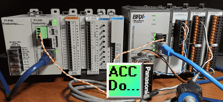
We will now look at the productivity 1000 plc modbus tcp rtu communication to the BX-MBIO controller.
The Productivity 1000 PLC can communicate to a remote I/O (input and output) controller modules using the Modbus protocol for communications. The BX-MBIO provides both Modbus RTU and Modbus TCP interfaces. Modbus RTU is a serial communication and Modbus TCP is an Ethernet communication. Modbus RTU is supported over an RS-485 serial connection. Modbus TCP is supported over an Ethernet connection. They function as listening/replying devices (slave, server) and can connect with any mastering (master, client) device that communicates using the Modbus protocol.
Previously we looked at the BX-MBIO Modbus RTU TCP Remote IO Controller wiring and configuration.
Modbus RTU TCP Remote IO Controller BX-MBIO
– BX-MBIO Hardware Video
– BX-MBIO Powering and Configuring Video
We will connect the Productivity 1000 PLC to the Modbus remote IO. This will be done using the Modbus TCP and Modbus RTU protocol. Ethernet and serial RS485 communication to the BX-MBIO unit will be the media.
The BX-MBIO remote I/O expansion units feature the following:
• RJ45 Ethernet port for communications via Modbus TCP
• RS485 serial port for communications via Modbus RTU
• Supports up to 8 additional Expansion Modules (Add the discrete or analog I/O you require)
• AC and DC powered units available
• AC powered units include an integral 24VDC auxiliary output power supply
• Power connector and serial port connector included
Let’s get started.
Previously in this Productivity 1000 series PLC, we have discussed:
System Hardware – Video
Installing the Software – Video
Establishing Communication – Video
First Program – Video
Documenting the Program – Video
Monitoring and Testing the Program – Video
Online Editing and Debug Mode – Video
Numbering Systems and Tag Database – Video
Contact and Coil Instructions – Video
Timer Instructions – Video
Counter Instructions – Video
Math Instructions – Video
Data Handling Instructions Part 1 – Video
Data Handling Instructions Part 2 – Video
Array Functions Part 1 – Video
Array Functions Part 2 – Video
Array Functions Part 3 – Video
Program Control – Video
Drum Sequencer Instructions – Video
Data Logger – Video
Web Server – Video
Modbus RTU Serial Communication – Video
Modbus TCP Ethernet Communication – Video
Firmware Update – Video
AdvancedHMI Modbus TCP Ethernet Communication – Video
Email and Text Communication – Video
PID Instruction – Video
PID Ramp Soak Instruction – Video
Stride Field Remote IO Modules Modbus TCP Ethernet
– Unboxing SIO MB12CDR and SIO MB04ADS Video
– Powering and Configuring Video
Productivity 1000 PLC to Stride Field IO Modbus TCP – Video
Modbus RTU TCP Remote IO Controller BX-MBIO
– BX-MBIO Hardware Video
– BX-MBIO Powering and Configuring Video
Our entire P1000 series can be found here.
The programming software and manuals can be downloaded from the Automation Direct website free of charge.
Watch the video below to see P1000 Productivity PLC control analog and digital inputs and outputs remotely.

Productivity 1000 PLC System Modbus Setup – Client (Master)
Our productivity plc will act as the Modbus Client (Master). It will communicate to the BRX BX-MBIO remote I/O which are Modbus Servers (Slaves).
Call up the Hardware Configuration window by using the main menu | Setup | Hardware Config.
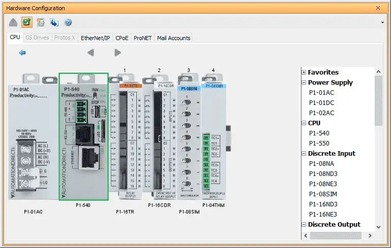
Double click on the CPU module to call up the P1-540 window.
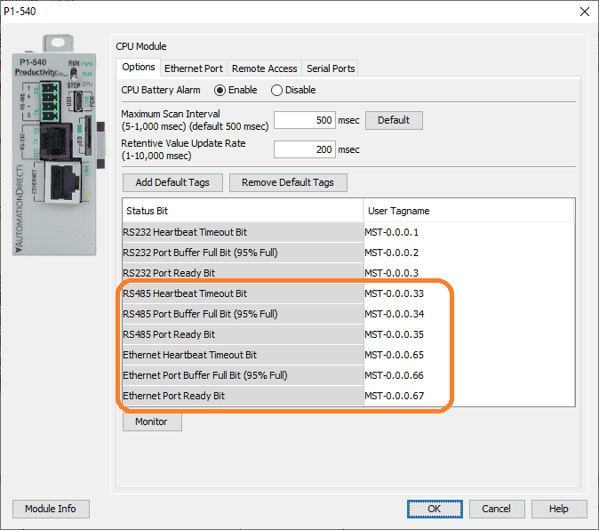
The options tab has the status bits and user tagnames for the RS485 and Ethernet ports that we will be using in our program. The Heartbeat Timeout Bit can be useful for picking up errors in our program with the remote input and output unit.
Select the Ethernet Port tab.
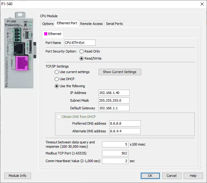
Here is where we can set our IP address for the P1-540 PLC Ethernet port. We will leave the timeout, Modbus TCP port, and Comm Heartbeat Value as their default.
Productivity 1000 PLC System Modbus RTU Setup – Master (Client)
Select the Serial Ports tab on the P1-540 window.
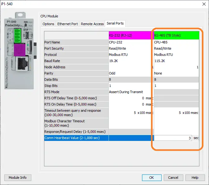
We will set the settings as indicated above under the RS-485 (Terminal Block – TB Style)
The port settings (baud rate, data bits, stop bits, parity, etc.) must match the settings on the BX-MBIO remote IO unit. Select OK. The protocol is automatically selected as Modbus.
The P1000 PLC is now ready to be a Modbus RTU Client (Master).
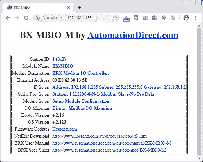
BX-MBIO Modbus Server (Slave) Setup Address and Parameters
Previously we used NetEdit3 and a web browser to configure our modbus remote input and output unit. See the links above.
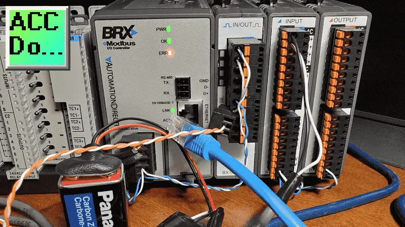
Start NetEdit3 by selecting it from the Applications section of the Launchpad on our Do-More Designer software.
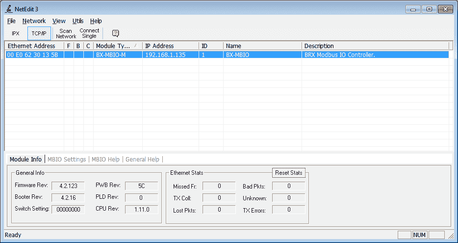
Select the BX-MBIO module from the list that was scanned and then select the MBIO Settings tab at the bottom.
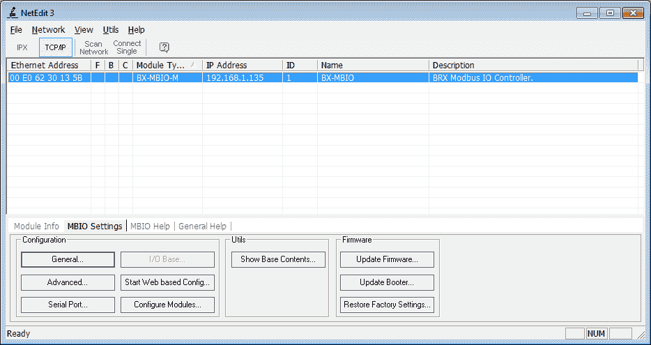
Select the General… button.
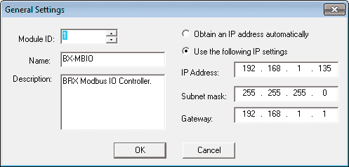
Here is the IP address for our unit.
Select the Serial Port… button.
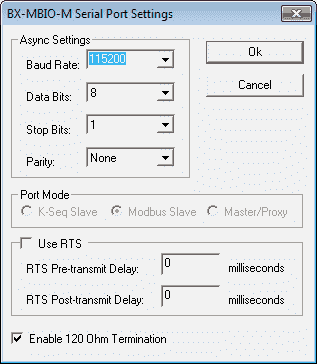
Here are the port settings for the modbus RTU remote IO unit. This must match the settings on the P1000 PLC that we set above.
BX-MBIO Modbus Addresses
Using the web-based configuration from the NetEdit3 software we can call up the main menu. This can be done also by entering the IP address of the MBIO unit in your web browser software.
Select display modbus I/O mapping. This will show us the Modbus addresses that we will need to program our PLC.
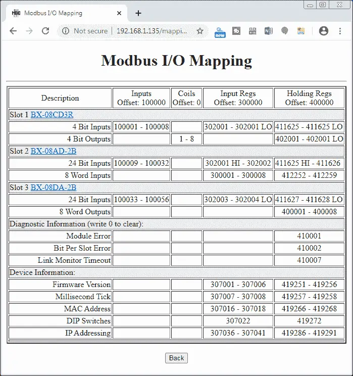
This table will now be used to program our productivity 1000 PLC.
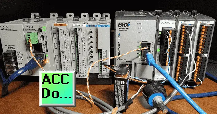
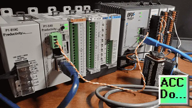
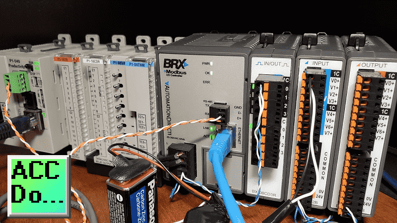
System Wiring
The first relay output of the BX-08CD3R will be wired to the input of the first point on the same mixed IO unit. This unit is located on our remote input and output modbus unit. This will allow us to see the input working.
Using the voltage input tester that we created previously, we will be wiring this up to the first voltage input on the BX-08AD-2B unit.
Create an Analog Voltage Input Tester for a PLC – Video
P1000 PLC Program

Our sample program has a Main program that will do the overall logic. The two others run every scan program that will handle the communications to the BX-MBIO unit.
– Modbus TCP BX-MBIO Communication – Modbus TCP via Ethernet RJ45
– Modbus RTU BX-MBIO Communication – Modbus RTU via Serial RS485
Main Program
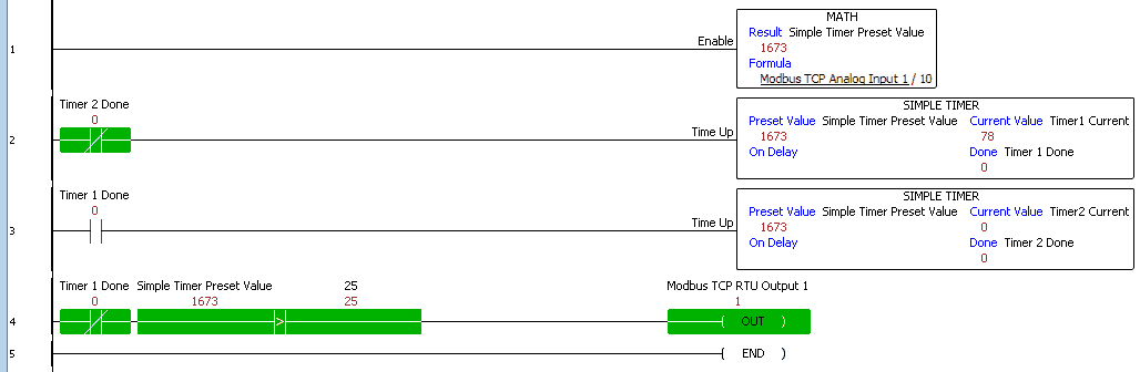
Unconditional rung 1 will take the Analog Input 1 signal coming from the remote Modbus input and output unit and divide by 10. This will be used in our simple timers for the following rungs.
Rung 2 and 3 will set up timers based on the math result from the previous rung.
If timer 0 is not done, rung 4 will compare the simple timer preset value to a value of 100. This is to ensure that the timer will not chatter the output if the value becomes too low. The first discrete output relay is then turned on.
Modbus TCP BX-MBIO Communication
Modbus TCP Communication to BX-MBIO
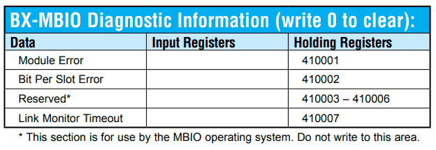
The above Modbus address list is where the BX-MBIO errors are located. Writing a 0 into these addresses will clear the error. Link Monitor Timeout is used to determine the amount of time between Modbus transmissions before the BX-MBIO displays an error.
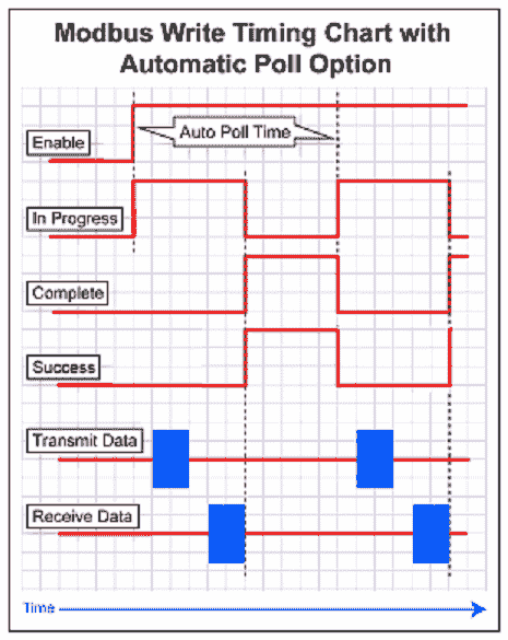
The productivity PLC incorporates an automatic poll option. The timing of the communications is taken care of within the instruction. This is a nice feature for communication.
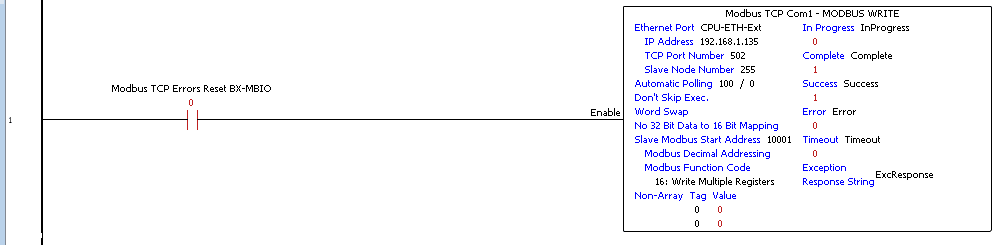
Upon detection of a remote I/O error, reset the error on the remote I/O rack. This is done using the Modbus Write instruction. We write a 0 into the two error registers.
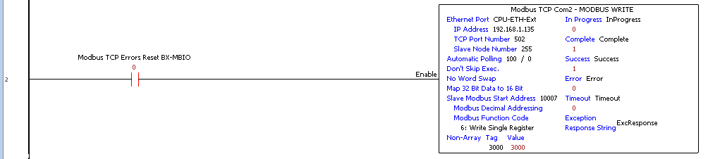
Set the link monitor timeout for 3 seconds. The value of 3000 is placed in register 410007.
This is what it will look like when a link monitor timeout occurs.
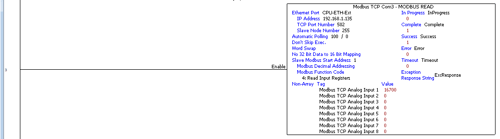
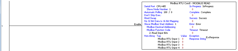
Read the analog inputs on the Modbus remote I/O unit.
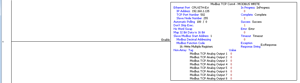
Write the analog outputs on the Modbus remote I/O unit.
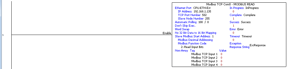
Read the discrete inputs on the Modbus remote I/O unit.

Use the Pack Bits instruction to move the output bits into a word. Write the discrete output word on the Modbus remote I/O unit.
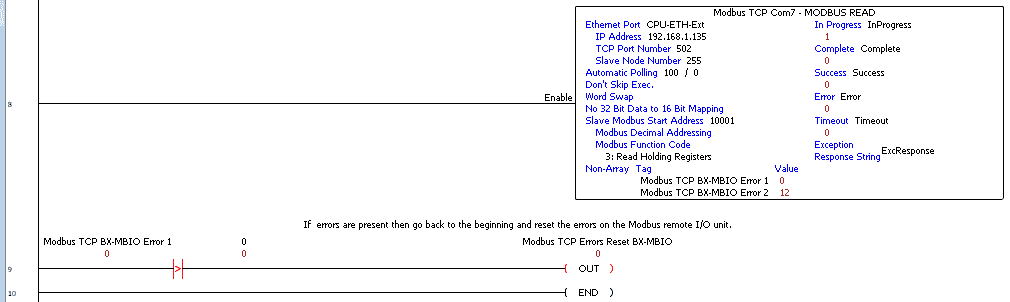
Read the Modbus remote input and output rack unit errors.
If an error is read, then turn on Modbus TCP Errors Reset BX-MBIO bit. This will then be used to reset the errors.
Modbus_RTU_MBIO
Modbus RTU Communication to BX-MBIO
The above Modbus address list is where the BX-MBIO errors are located. Writing a 0 into these addresses will clear the error. Link Monitor Timeout is used to determine the amount of time between Modbus transmissions before the BX-MBIO displays an error.
The productivity PLC incorporates an automatic poll option. The timing of the communications is taken care of within the instruction. This is a nice feature for communication.
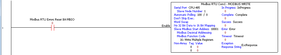
Upon detection of a remote I/O error, reset the error on the remote I/O rack. This is done using the Modbus Write instruction. We write a 0 into the two error registers.
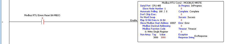
Set the link monitor timeout for 3 seconds. The value of 3000 is placed in register 410007.
This is what it will look like when a link monitor timeout occurs.
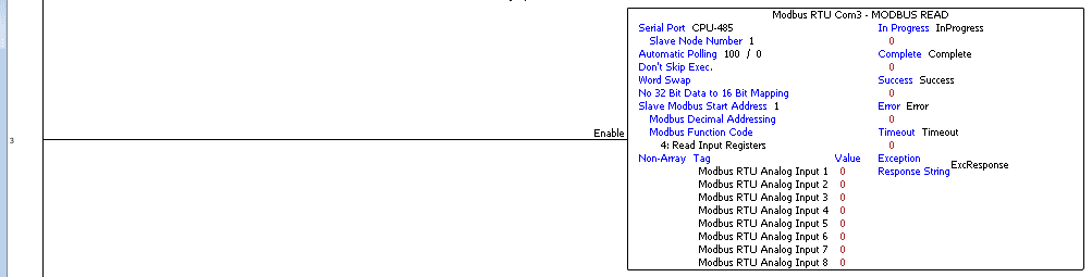
Read the analog inputs on the Modbus remote I/O unit.
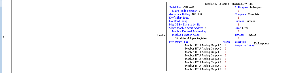
Write the analog outputs on the Modbus remote I/O unit.
Read the discrete inputs on the Modbus remote I/O unit.
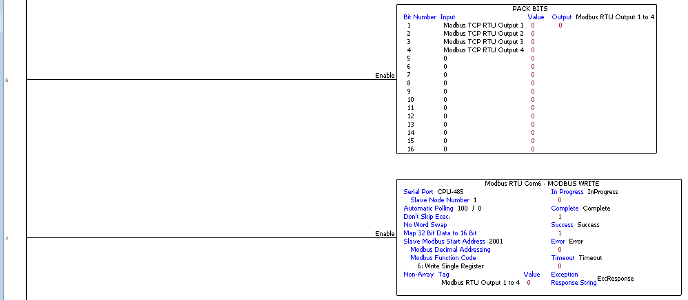
Use the Pack Bits instruction to move the output bits into a word. Write the discrete output word on the Modbus remote I/O unit.
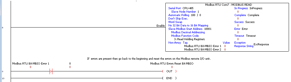
Read the Modbus remote input and output rack unit errors.
If an error is read, then turn on Modbus RTU Errors Reset BX-MBIO bit. This will then be used to reset the errors.
Watch the videos below to see the running of the P1000 PLC program to communicate to our BX-MBIO Modbus remote I/O unit.
We have included programming for Modbus TCP and RTU. (This is done for demonstration purposes. Normally you would use either Modbus TCP or RTU and not both.)
Download the Productivity 1000 PLC program here.
Productivity 1000 Series PLC from Automation Direct
Overview Link (Additional Information on the Unit)
Configuration (Configure and purchase a system – BOM)
User Manual and Inserts (Installation and Setup Guides)
Productivity Suite Programming Software (Free Download Link)
This software contains all of the instruction sets and help files for the Productivity Series.
Modbus Learning Links:
Simply Modbus Frequently Asked Questions
Modbus TCP/IP Overview – Real Time Automation
All You Need to Know About Modbus RTU – Video
Watch on YouTube: Productivity 1000 PLC to Modbus TCP RTU Remote IO Controller BX-MBIO
If you have any questions or need further information please contact me.
Thank you,
Garry
If you’re like most of my readers, you’re committed to learning about technology. Numbering systems used in PLC’s are not difficult to learn and understand. We will walk through the numbering systems used in PLCs. This includes Bits, Decimal, Hexadecimal, ASCII and Floating Point.
To get this free article, subscribe to my free email newsletter.
Use the information to inform other people how numbering systems work. Sign up now.

The ‘Robust Data Logging for Free’ eBook is also available as a free download. The link is included when you subscribe to ACC Automation.