Secret to ONE SHOT Edge Triggers in PLC Scan?
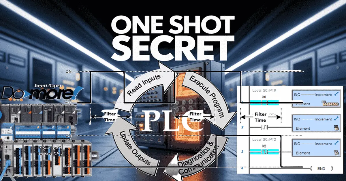
Did you know that understanding edge triggers can drastically improve your PLC understanding? How one-shots work within the PLC scan is vital in programming PLCs. In this post, we’ll dive into the world of programmable logic controllers and explore the techniques and strategy secrets you need to know to trigger your edges precisely and accurately. … Read more