We will use Modbus TCP (Ethernet) to connect and program the XGB PLC to the Machine Simulator Easy Transfer Line. The Machine Simulator (EasyPLC) Software Suite is a comprehensive package with PLC, HMI, and Machine Simulator software. It features a Machine Simulator (MS) that allows virtual communication with many programmable logic controllers (PLCs) in a 3D world with real-time graphics and physical properties. Our PLC programming example will follow the five steps to PLC program development.
We will use the simulator’s pre-built easy transfer line machine to learn PLC programming. We will develop ladder logic, connect via Modbus TCP, and test our program using the free XG5000 PLC programming software and XGB PLC. Let’s begin!
Learn PLC programming the easy way. See below for a 10% discount on this cost-effective learning tool. Invest in yourself today.
The entire series can be found here.
Here are some previous posts we have done:
Easy PLC Installing the Software – Video
EasyPLC Software Suite – Quick Start – Video
Click PLC – Easy Transfer Line Programming – Video
Productivity PLC Simulator – Chain Conveyor MS – Video
Do-More PLC – EasyPLC Box Selection Program – Video
Click PLC EasyPLC Gantry Simulator – Video
Click PLC Simple Conveyor EasyPLC – Video
EasyPLC Paint Line Bit Shift – BRX Do-More PLC – Video
Click PLC – EasyPLC PLC Mixer Programming – Video
Click PLC EasyPLC Warehouse Stacker Example – Video
– Operation Video
EasyPLC Machine Simulator Productivity PLC Robotic Cell – Video
EasyPLC Simulator Robotic Cell Click PLC – Video
Palletizing Conveyor Programming Do-More PLC – Video
Palletizing Conveyor Programming – Click PLC – Video
Product Quality Verification! Do-More PLC Sequencer – Video
Revolutionize Learning PLCs with Pallet 3D Sim! – Video
Robot Packing PLC Program Development – Video
Box Dumper Easily Learn PLC Programming – Video
Innovative Solution for Mixing Ink and Bottling – Video
Benchwork 1 Do-More Practice PLC Programming – Video
Define the task: (Step 1 – XGB PLC Easy Transfer Line)
The first step of PLC program development is to define the task to determine what must be done. Machine Simulator (EasyPLC) software suite contains this easy transfer line example in the machine simulator. This is just one of many machines with the software so you can learn and develop your PLC programming skills.
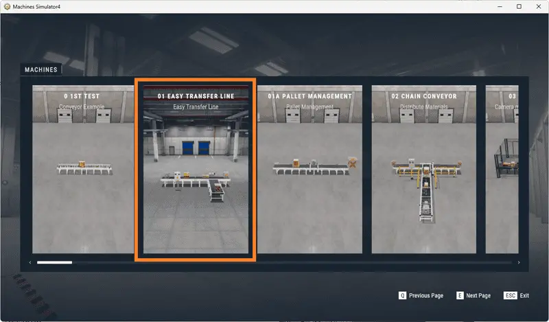
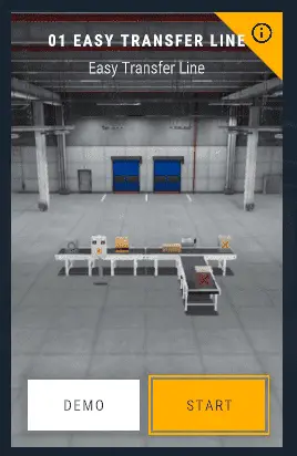
Launch Machine Simulator 4 and access the “Machines” menu. The “01 Easy Transfer Line” option will be seen on the pre-configured machines. We will program this machine.
As you move your mouse over the machine picture, you can select the icon at the top right side. This will show you the machine description.
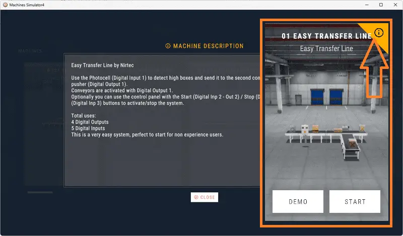
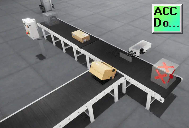
The photocell detects high boxes and sends them to the second conveyor using the pneumatic pusher. Conveyors are activated with digital output 1. We will also include the control panel. The green start light will be on when the system is ready to run. When the start is pressed, the stop light will be on to indicate how the system is stopped. Pressing the emergency stop button will turn off both lights and stop the sequence.
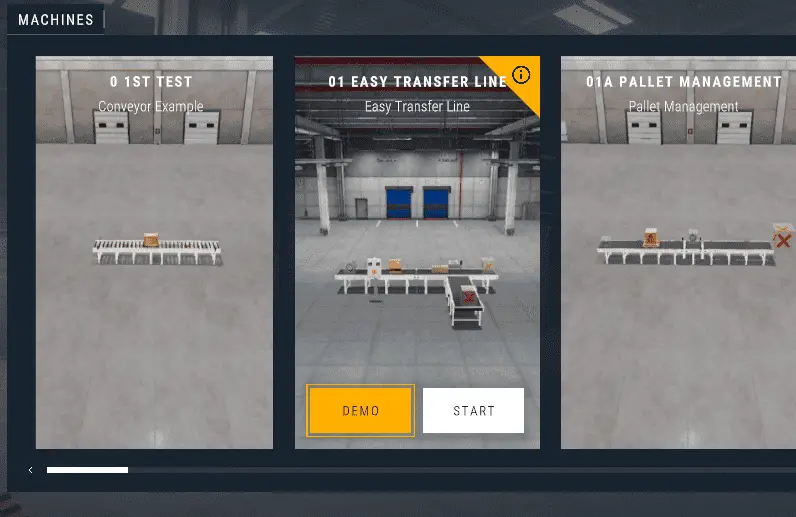
The machine simulator has a demo mode for the built-in machines. Select close from the machine description window. Select the demo mode for the easy transfer line. This mode shows you the operation so you can better understand what needs to be accomplished.
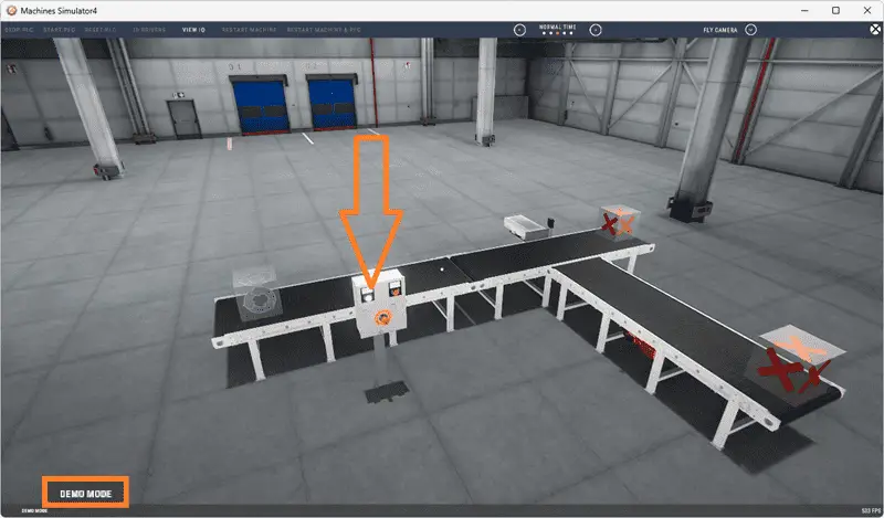
Press the control buttons in the simulator to operate the machine. Take some time to explore the 3D virtual environment using the navigation menu at the top of the window. The default selection allows you to move freely without colliding with any components, while the first-person and third-person modes provide different perspectives.
Exploring the demo mode will help you understand how the easy transfer line operates. This will help you develop the PLC program to control the machine’s actions effectively.
Once we understand the task and have familiarized ourselves with the easy transfer operation, we can proceed to the next step in developing the XGB PLC program using the XG5000 programming software. By following these steps and gaining hands-on experience with the Machine Simulator learning suite and the XGB, you will be well on your way to mastering PLC programming and applying your knowledge to real-world scenarios. So, let’s continue our journey and move on to the next step in the process.
Watch the sequence of operation video below.
Define the Inputs and Outputs: (Step 2 – XGB PLC Easy Transfer Line)
The written version specifies that we will require four digital outputs and five digital inputs for our easy transfer line. Inputs are signals or data received by the PLC, while outputs are signals or data sent by the PLC to control external devices. By understanding the inputs and outputs, you can develop a program that reads the status of the inputs and activates the appropriate outputs. While still in demo mode, select View IO to display the inputs and outputs required for this machine. These PLC IOs are for the machine’s physical running and do not include additional registers or bits that may be required for programming.
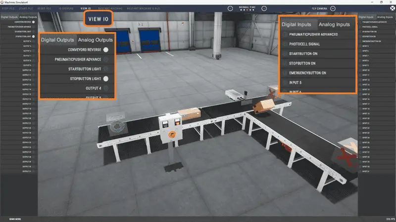
This will now show the digital outputs on the left side of the screen and the digital inputs on the right side.
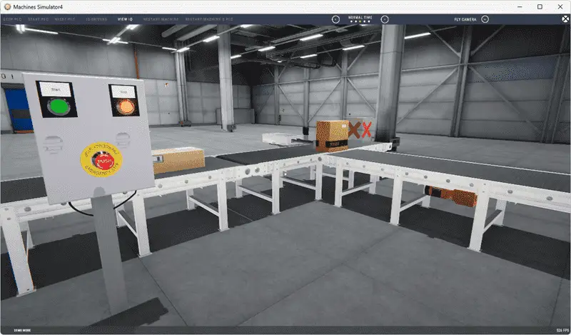
If you are unsure what an output or input is doing, start the easy transfer line machine in Start mode.
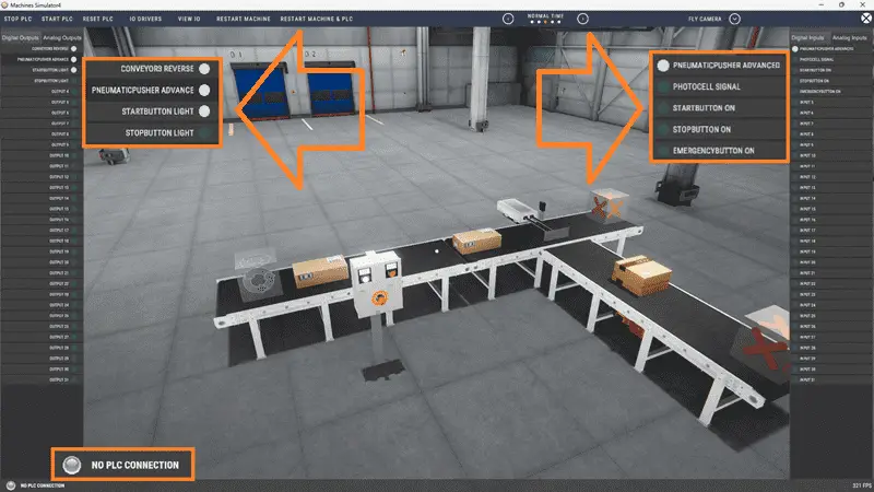
Select View IO along the top of the Easy Transfer Line machine simulator window.
You can manually run the easy transfer line without any control or PLC connection. Select the outputs on the left to turn on, and monitor the inputs on the right.
Defining the inputs and outputs establishes the communication between the PLC and the external devices. This allows the PLC program to monitor the inputs and continuously decide based on their status. The program can then activate the appropriate outputs to control the easy transfer line operation.
The following table will define the inputs and outputs (IO) and Modbus addresses in the XGB PLC we will use for this program. (Machine Simulator Easy Transfer Line)
| Digital Type | Description | Do-More PLC Modbus Address | Machine Simulator Modbus Address |
| PLC Output – MS Input | Conveyor | %MX3216 – 10001 | 0 |
| PLC Output – MS Input | Pneumatic Pusher | %MX3217 – 10002 | 1 |
| PLC Output – MS Input | Start PB Light | %MX3218 – 10003 | 2 |
| PLC Output – MS Input | Stop PB Light | %MX3219 – 10004 | 3 |
| PLC Input – MS Output | Pneumatic Cylinder Extend | %MX6416 – 1 | 0 |
| PLC Input – MS Output | Photocell | %MX6417 – 2 | 1 |
| PLC Input – MS Output | Start PB | %MX6418 – 3 | 2 |
| PLC Input – MS Output | Stop PB | %MX6419 – 4 | 3 |
| PLC Input – MS Output | Emergency Stop | %MX6420 – 5 | 4 |
It is important to note that PLC programs operate cyclically, meaning they continuously read the inputs and set the outputs. This ensures that the program is responsive to system changes and can adapt accordingly. By understanding the inputs and outputs and their relationship to the overall system, you can develop a logical sequence of operation for the Easy Transfer Line PLC program. This is our next step.
Develop a logical sequence of operation: (Step 3 – XGB PLC Easy Transfer Line)
A flow chart or sequence table is used to understand the process that needs to be controlled thoroughly. It must also answer questions like the following:
What happens when electrical power and/or pneumatic air is lost? What happens when the input/output devices fail? Do we need redundancy?
Knowing all of these answers upfront is vital in developing the PLC program. This step is where you can save yourself a lot of work by understanding everything about the operation. It will help prevent you from continuously re-writing the PLC program logic.
Here is the sequence table for the easy transfer line.
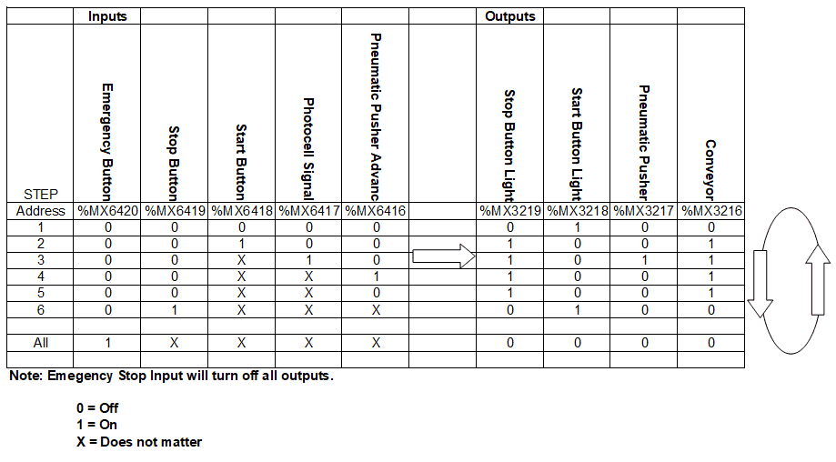
You read the input conditions and then look to the right-hand side for the outputs that will be set. The following line will then look for the input conditions again.
As a PLC programmer, it is vital to have a comprehensive understanding of the machine’s sequence and operation before starting the programming process. This can be achieved by asking questions or reviewing existing documentation to ensure a clear understanding of the logical steps involved. This step sets the foundation for the subsequent development of the XGB PLC program, which will be covered in the next section.
Develop the PLC program: (Step 4 – XGB PLC Easy Transfer Line)
Writing the ladder logic code for the PLC example will be the next step in our program development. Start the XG5000 programming software and start a new project. This can be done by selecting the New Project under the project tab on the main menu, using the shortcut Ctrl+N, or the new project icon on the main ribbon.
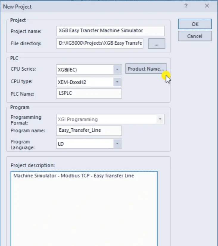
We will name the project and select the XGB PLC for our program. Comments can also be added for future reference. Select OK.
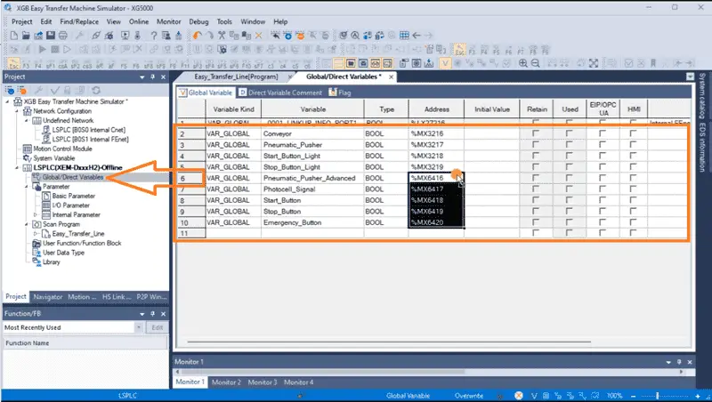
Our scan program will be displayed. Under the LSPLC that we selected the program, select Global / Direct Variables. We can now enter the variables for our Machine Simulator Easy Transfer Line. To aid in setting the variables, you can see that once an address is entered, we can highlight it, click and drag to populate the other variables below it.
The Modbus Addresses that we will use will match the settings for the communication to the XGB PLC. Here is the map. These addresses will be written when we set up the communication and Modbus Server.
As we program, remember to save your work often.
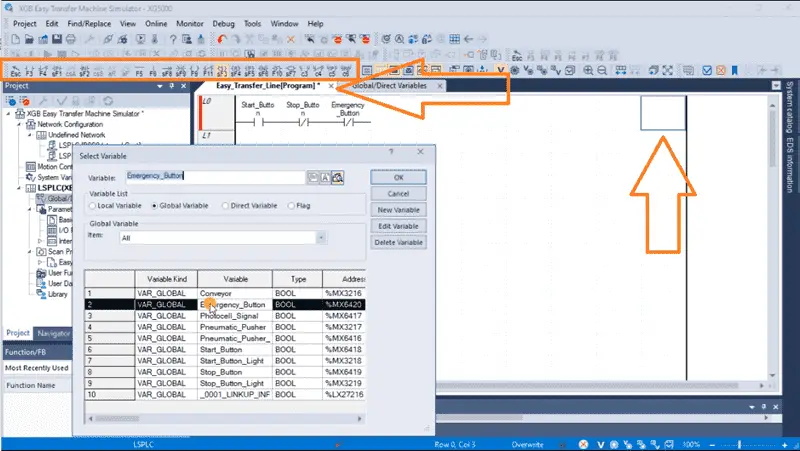
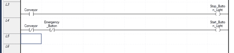
Select the scan program tab. We can now create our ladder logic program using the input and output icons on the menu bar. As we enter the instructions, we can select the variables.
Starting and stopping the conveyor is done with a set and reset instruction.
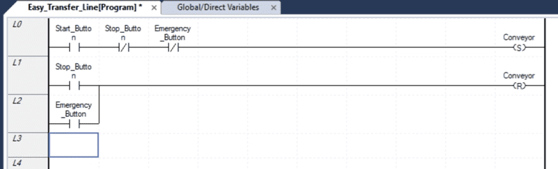
When the emergency stop is activated, both lights are off. This indicates to the operator that the emergency stop must be reset.
When the photocell sees the high boxes, this activates the pneumatic pusher. When the pusher reaches the extended position, it will reset the pneumatic pusher.
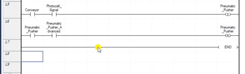
An END statement will indicate that this is where the program ends and to repeat the scan. Save your program. It is important always to save your program during programming.
Double-click on the Internal FEnet (Fast Ethernet network) port.
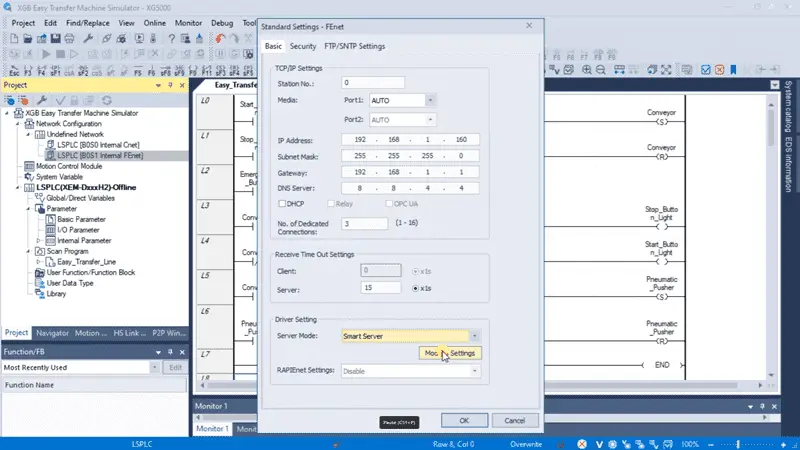
This will call up the standard settings for the port. Under the basic tab, we can assign an IP address and settings to work with our network. Select the “Smart Server” for the server mode. This will include the Modbus server.
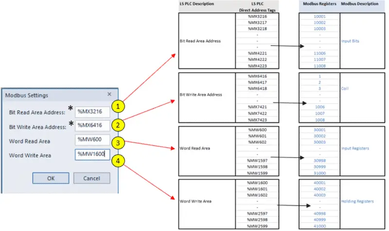
Select the Modbus Settings button.
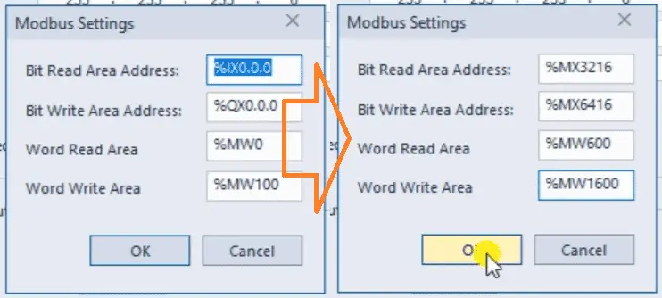
Change the default Modbus address settings to those we have selected for our program. Select OK.
We can now connect and transfer the program to our XGB PLC.
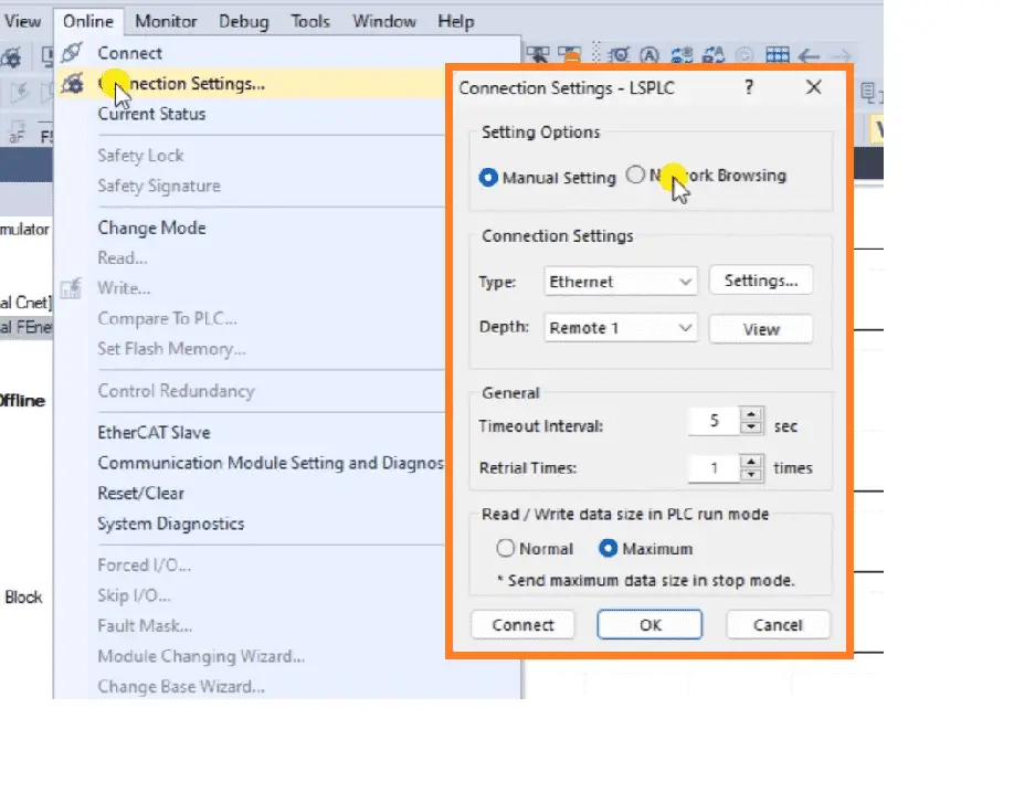
If we are unsure of the connection to the XGB you can use the network browsing to discover the IP address.
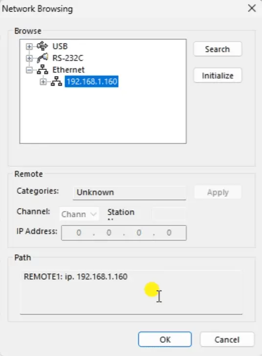
Once the PLC is discovered on your network, you can select OK. You can now select OK or connect from the connection settings window.
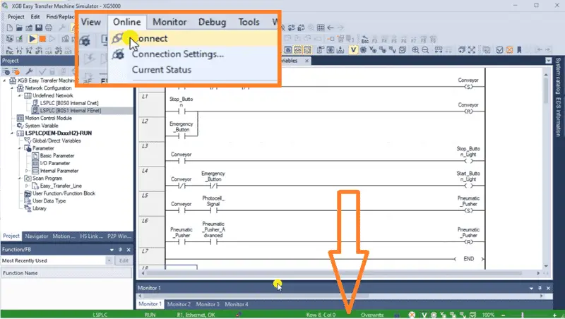
You can also use the connect from the main menu. The bottom bar of the XG5000 programming software will turn green, indicating that the PLC is connected and in run mode.
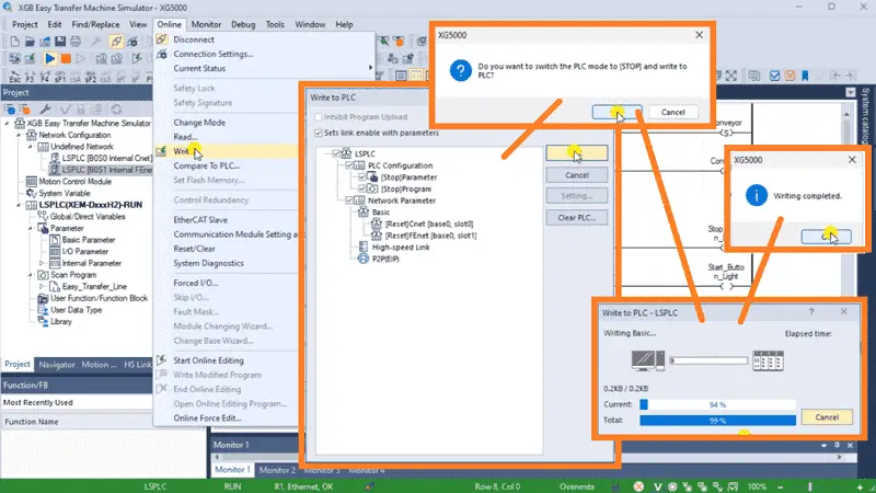
Select “Write…” from the Online option in the main menu. You will then stop the PLC and transfer the program and settings like Modbus into the controller. We now have our PLC ready to test.
Watch the video below to see this program in operation.
Test the program: (Step 5 – XGB PLC Easy Transfer Line)
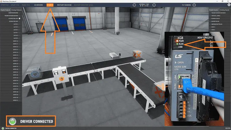
To ensure the functionality and accuracy of the XGB PLC practice program for the Easy Transfer Line machine, it is essential to test the program thoroughly. Utilizing a Machine Simulator (MS) is an effective way. Using the MS, you can simulate the operation of the Easy Transfer Line machine without needing physical hardware, minimizing the risk of damage during the testing phase. We will use Modbus TCP on our LS XGB PLC to communicate with the EasyPLC Machine Simulator. Call up the Easy Transfer Line machine simulator in start mode.
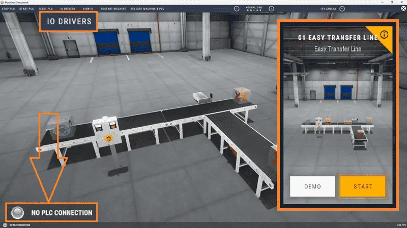
The status of the machine simulator will be at the bottom of the screen. Currently, we have no PLC connected. Select IO Drivers on the top middle of the screen.
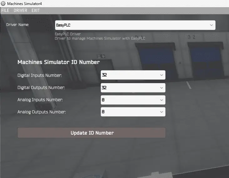
The machine simulator IO number will be displayed. Ensure we select more IO than required for our Easy Transfer Line machine. The EasyPLC driver is selected by default.
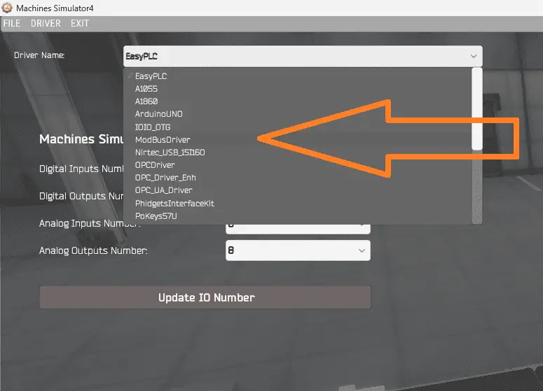
Under the driver pull-down menu, select “ModBusDriver.” This driver will communicate Modbus TCP (Ethernet) and Modbus RTU (Serial).
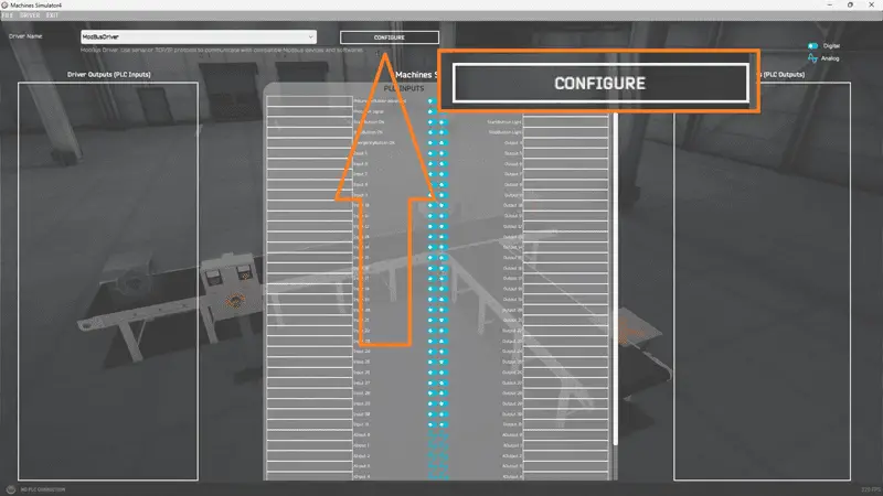
Select the configure button.
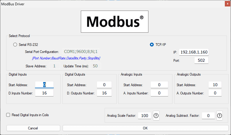
We can now enter the information for our Modbus driver. Select TCP/IP. This means the Ethernet port on the computer will communicate with the XGB PLC. The digital inputs from MS to the XGB PLC will be %MX3216 to %MX3219. Digital outputs from MS to the XGB PLC will be %MX6416 to %MX6420. Select the OK button.
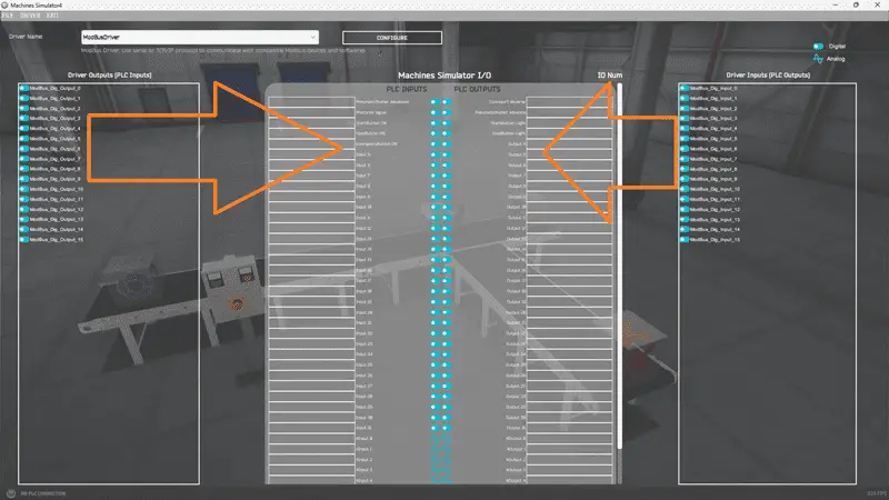
You will now see the inputs and outputs specified for the Modbus driver. We can now manually assign the driver outputs to the PLC inputs and driver inputs to the PLC outputs. However, the automatic assignment works well and will save you time.
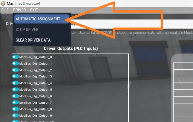
Select Automatic Assignment from the driver option in the main menu.
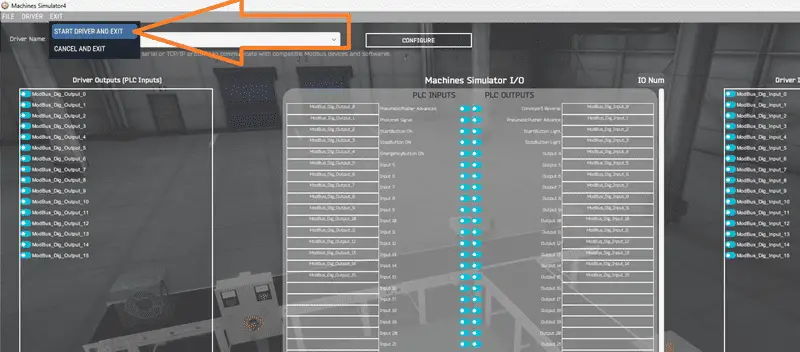
This will automatically assign the PLC simulator IO to the Machine Simulator IO. Select Start Driver and exit from the main menu.
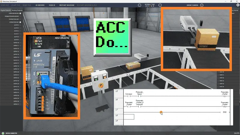
On the bottom left side of the window, the driver communicates with the XGB PLC with a green light. Select view IO to see the machine simulator’s input and output status. Ensure that the XGB PLC is in run mode. We can now operate the Easy Transfer Line machine. The inputs and outputs of the MS will correspond to the PLC controller.
Using Machine Simulator (MS) to test the program will ensure that our program works. Troubleshooting is quickly done without damage to any physical hardware. This testing phase is crucial in ensuring the safe and reliable operation of the Easy Transfer Line machine.
You can practice your modification and debug by modifying the Easy Transfer Line machine operation in the following way:
– Add a counter for the large box conveyor to show the total. The control panel will need a reset button for this count.
– Calculate the rate of these boxes in boxes per hour.
Let me know how you make out in the comments below.
Download the PLC sample program and sequence table here.
Watch the video below to see the five steps of program development applied to the Easy Transfer Line machine. The machine simulator is one of the best applications for learning PLC programming.
When using EasyPLC, debugging is quickly done without damaging any equipment. You may modify your logic several times before you get everything right! To learn more about developing logic, check out our tutorials on the five steps to PLC program development.
Machine Simulator (EasyPLC) Software Suite is a complete PLC, HMI, and Machine Simulator Software package. This PLC learning package includes the following:
Easy PLC – PLC Simulation allows programming in Ladder, Grafcet, Logic Blocks, or Script.
HMI System – Easily create a visual human-machine interface (HMI)
Machine Simulator – A virtual 3D world with real-time graphics and physical properties. PLC programs can be tested using EasyPLC or through other interfaces. (Modbus RTU, TCP, etc.)
Machine Simulator Lite – Designed to run on Android Devices.
Machine Simulator VR – Virtual Reality comes to life so you can test, train, or practice your PLC programming.
Purchase your copy of this learning package for less than USD 95 for a single computer install or less than USD 110 to allow different computers.
Receive 10% off the price by typing in ACC in the comment section when you order. http://www.nirtec.com/index.php/purchase-price/
Learn PLC programming the easy way. Invest in yourself today.
Watch on YouTube: LS Electric XGB PLC Easy Transfer Program
If you have any questions or need further information, please contact me.
Thank you,
Garry
If you’re like most of my readers, you’re committed to learning about technology. Numbering systems used in PLCs are not challenging to learn and understand. We will walk through the numbering systems used in PLCs. This includes Bits, Decimals, Hexadecimal, ASCII, and Floating Points.
To get this free article, subscribe to my free email newsletter.
Use the information to inform other people how numbering systems work. Sign up now.

The ‘Robust Data Logging for Free’ eBook is also available for free download. The link is included when you subscribe to ACC Automation.