The Machine Simulator (MS) is part of the EasyPLC software suite. It has many built-in machines that are used to show different programming techniques. The industrial mixer is one of these machines. When the start pushbutton is energized it will fill up a tank until the lower level sensor is detected. The mixer blades will then be turned on until the top sensor is detected. The tank is then drained past the low sensor and the process repeats for 3 cycle times. Once the sequence is complete, the tank is completely drained and ready to start again.
 The Click PLC will be used to program this virtual 3D mixer machine. A DRUM instruction will be used in the PLC for the sequencing. Using the Click Plus PLC, we will connect to the mixing machine. This will be done using Modbus TCP (Ethernet) for communications. Using the five steps for program development we will show how this is programmed. Let’s get started.
Learn PLC programming the easy way. Invest in yourself today. See below on how to receive a 10% discount on this already cost-effective learning tool.
Previously we have done the following:
Easy PLC Installing the Software – Video
EasyPLC Software Suite – Quick Start – Video
Click PLC – Easy Transfer Line Programming – Video
Productivity PLC Simulator – Chain Conveyor MS – Video
Do-More PLC – EasyPLC Box Selection Program – Video
Click PLC EasyPLC Gantry Simulator – Video
Click PLC Simple Conveyor EasyPLC – Video
EasyPLC Paint Line Bit Shift – BRX Do-More PLC – Video
Define the task: (Step 1 – EasyPLC Mixer)
The first step of PLC program development is to determine what has to be done. Start the EasyPLC Machine Simulator (MS). Select the start button on the main page or select machines from the main menu on the top of the machines simulator window.
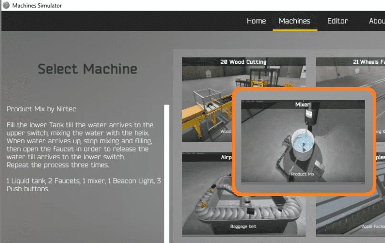 All of the available machines will now be displayed. Click on the Mixer. This is the example that we will be programming. To the left of the screen, information will be displayed on what the machine needs to do as well as some of the inputs and outputs required for the program.
Fill the lower tank till the water arrives at the upper switch, mixing the water with the helix. When the water arrives up, stop mixing and filling. Open the faucet in order to release the water till the tank arrives at the lower switch. Repeat the process three times. There is 1 liquid tank, 2 faucets, 1 mixer, 1 beacon light, and 3 push buttons.
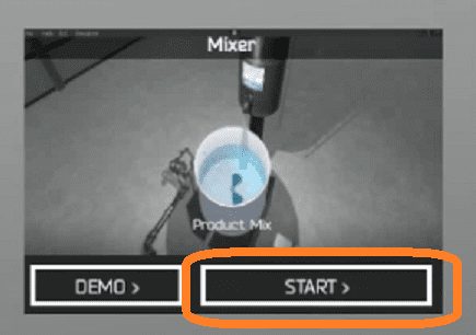
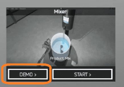 The machine simulator has a demo mode for the built-in machines. This will allow you to watch the operation of the mixer. Select the demo mode for the mixer machine.
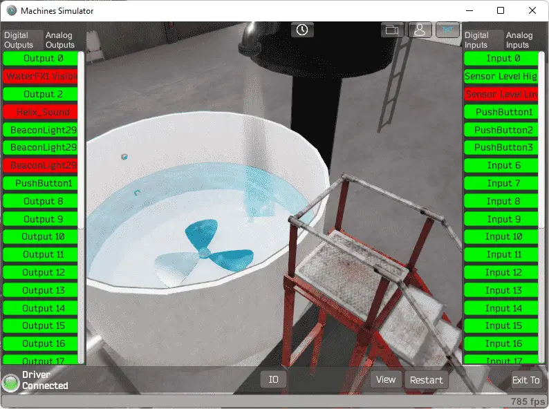
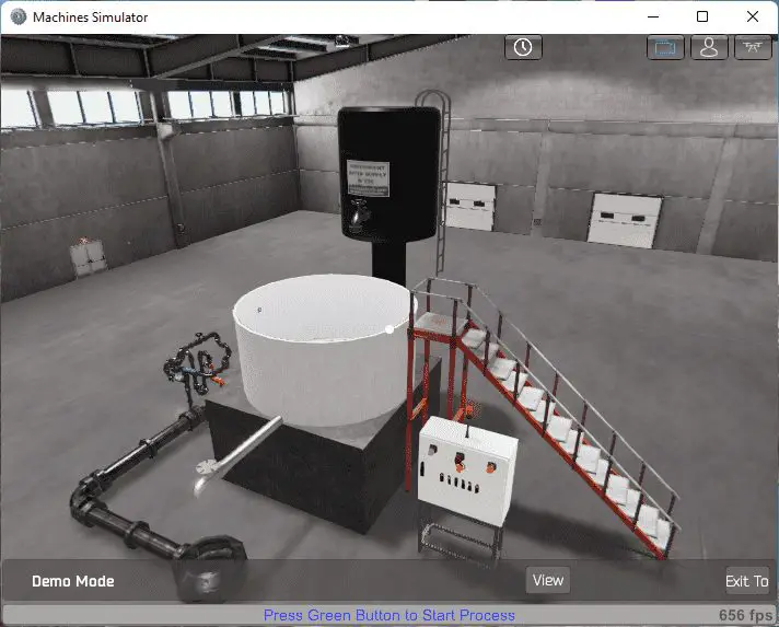 The mixer will operate showing you the basics of operation. Select the start push button that is flashing to start the sequence of operation.
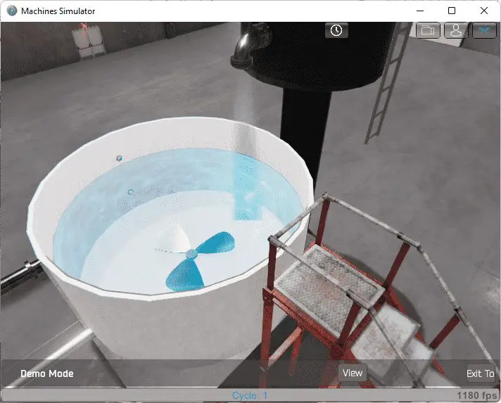 Move around the 3D virtual environment. There are three icons on the top of the window that will allow you to move around this 3D environment. The first icon is the default selection. This will allow you to move around without bumping into the components. The first-person mode will mimic a person in your 3D learning world. The last icon will automatically show you around this virtual environment.
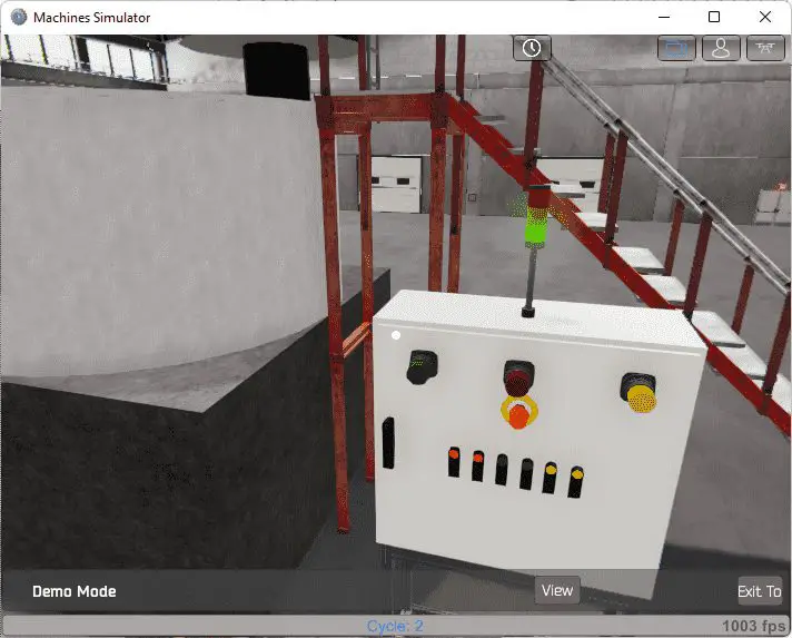
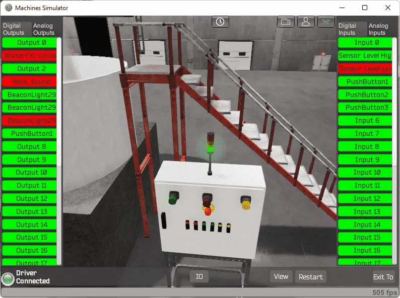
The control panel has three pushbuttons. Start, stop, and reset will control the mixer. The beacon light red and green will be on depending on the mixer condition.
 Once we have a good understanding of what has to be done, we can now move on to the next step in the PLC program development.
Define the Inputs and Outputs: (Step 2 – EasyPLC Mixer)
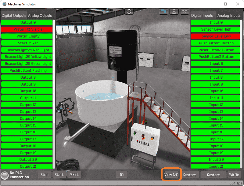
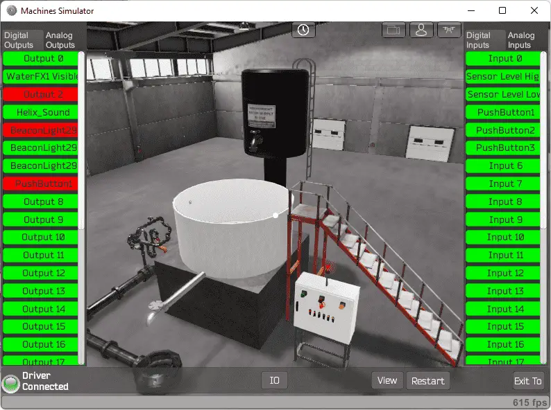
In demo mode select View IO at the bottom of the machine simulator window. This will display the inputs and outputs required for this mixer machine.
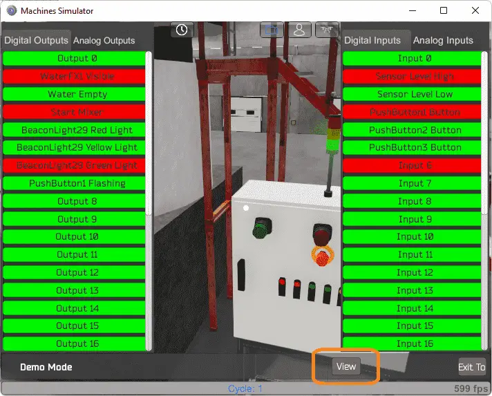 The EasyPLC mixer example will require 7 digital outputs and 5 digital inputs.
 If you are unsure as to what output or input is doing, start the mixer machine line in Start mode. Select the View IO on the bottom middle of the machine simulator window. You can manually run the mixer without any control or PLC connected.
 Clicking on the outputs will allow you to manually turn them on. You can then monitor the inputs to see their operation. Using the mouse, you can move the bottles in this 3D virtual environment. The restart button on the bottom of the machine simulator window will reset the scene back to the start.
The following table will define the inputs and outputs (IO) and Modbus addresses in the Click PLC that we will use for this program.
| Digital Type | Description | Click PLC Modbus Address | Machine Simulator Modbus Address |
| PLC Output – MS Input | Output 0 | 8225 – Y101 | 8224 |
| PLC Output – MS Input | Water FX1 Visible | 8226 – Y102 | 8225 |
| PLC Output – MS Input | Water Empty | 8227 – Y103 | 8226 |
| PLC Output – MS Input | Red Beacon Light | 8228 – Y104 | 8227 |
| PLC Output – MS Input | Yellow Beacon Light | 8229 – Y105 | 8228 |
| PLC Output – MS Input | Green Beacon Light | 8230 – Y106 | 8229 |
| PLC Output – MS Input | Pushbutton 1 Green Flashing | 8231 – Y107 | 8230 |
| PLC Input – MS Output | Input 0 | 100033 – X101 | 32 |
| PLC Input – MS Output | Sensor Level High | 100034 – X102 | 33 |
| PLC Input – MS Output | Sensor Level Low | 100035 – X103 | 34 |
| PLC Input – MS Output | Pushbutton 1 Green Start | 100036 – X104 | 35 |
| PLC Input – MS Output | Pushbutton 2 Red Stop | 100037 – X105 | 36 |
| PLC Input – MS Output | Pushbutton 3 Yellow Reset/Jog | 100038 – X106 | 37 |
Note: The machine simulator will be offset by one on the Modbus Addresses.
See the video below for the demo mode and determining inputs and outputs.
Develop a logical sequence of operation: (Step 3 – EasyPLC Mixer)
A flow chart or sequence table is used to fully understand the process that needs to be controlled. It must also answer questions like the following:
What happens when electrical power and/or pneumatic air is lost? What happens when the input/output devices fail? Do we need redundancy?
This step is where you will spend the majority of your time. Understanding everything about the operation will save you time. It will help prevent you from continuously re-writing the PLC program logic. Knowing all of these answers upfront is vital in the development of the PLC program.
Here is a flow chart showing the sequence for the mixer program.
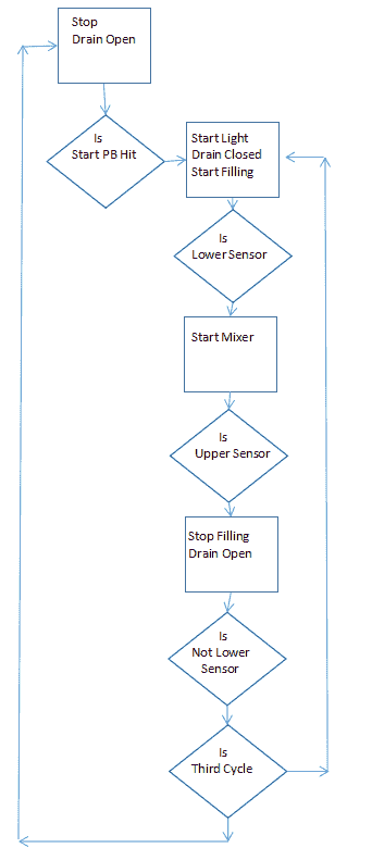 The EasyPLC mixer program in the Click PLC will use drum instruction.
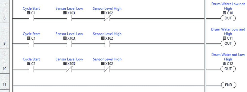
 The steps within a cycle can be split into three distinct sections.
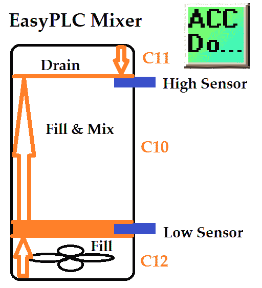
1. If the lower sensor is on and not the high sensor then the tank is filling and the mixer is on. The event input will be C10.
2. If the lower sensor and high sensor are on then stop the filling and mixing and drain. The event input will be C11.
3. If the lower and high sensor is off then close the drain and start filling. The event input will be C12.
If the machine is ready to start, the green push button will be flashing. The beacon light will be red. Upon selecting the green push button, the beacon light will be green. The tank will fill and empty three times, before stopping and be ready to start again.
The stop pushbutton will stop the sequence, and drain the tank. Starting again will pick up where it left off.
The yellow push button will reset the cycle if the system is not running. If it is running then the yellow push button will move to the next step in the sequence.
Future programs could ensure that the stop button will hold the process at the current spot. (No Draining) We could also keep track of the number of complete cycles. This could also be used to trigger maintenance checks on the valves depending on the number of times activated.
A PLC programmer must know how everything about the sequence and operation of the machine before programming.
Ask questions or view existing documentation to ensure that you know the logical steps to the machine operation.
Develop the Click PLC program: (Step 4 – EasyPLC Mixer)
Writing the ladder logic code for the PLC example will be the next step in our program development. We will be using the Click programming software and a Click Plus PLC PLC.
The Click PLC Series will take you through installing the program, communicating to the controller, instructions, and addressing the controller.
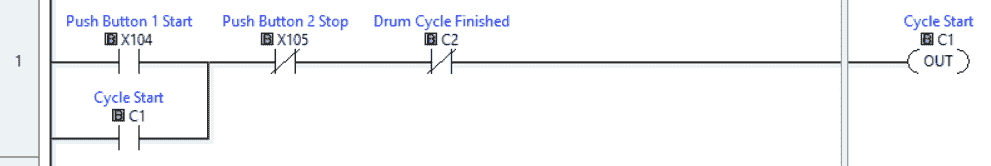 Push-button 1 (Green) will start the cycle sequencing. C1 is used to indicate the cycle start condition. This can be turned off with the stop pushbutton (Red) or when the drum cycle finishes.
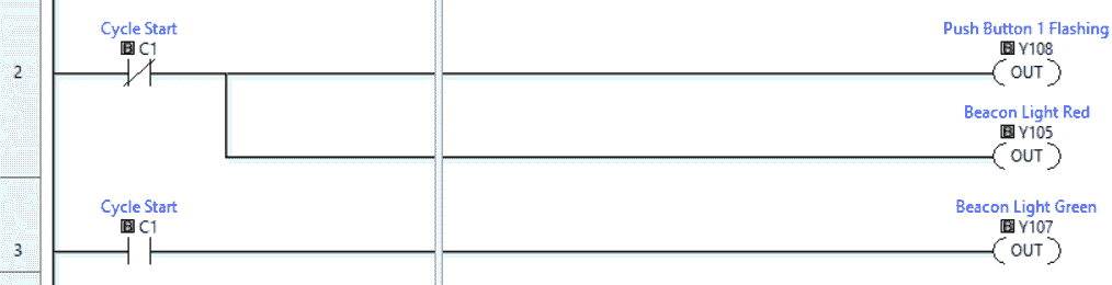 If the cycle start is off then the green push button 1 starts flashes and the red beacon light is on. If the cycle start is on then the green beacon light is on.
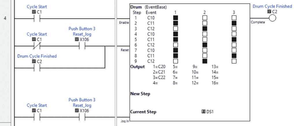 A Drum Instruction is used to control the mixer sequence. The drum has three outputs. (C20, C21, C22) These outputs will control the filling, draining, and mixing within our event sequence. Column 1 is C20 which is the filling output. Column 2 is C21 which is the draining output, and column 3 is C22 which is the mixing output. You can see that we just fill in what we require in a chart format to determine the three fills and drains for each cycle.
The cycle start is the condition input for the enable of our drum instruction. Reset of the drum is done by not having the cycle start with the yellow push button. This can also be reset by the drum cycle finish bit. A jog for the drum sequence is also programmed when the cycle start is on with the yellow push button.
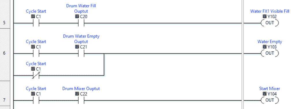 The drum instruction outputs are then used in series with the cycle start to set up the conditions for the 3D mixer outputs.
 The event inputs of the drum instruction will be set up with the 3D input conditions. See the above diagram in the sequence of events to view these three events. Watch the video below to see these inputs and outputs working within our drum instruction.
In order to communicate to the EasyPLC Machine Simulator, we must set up the Ethernet Port on the Click PLC. Select main menu | PLC | System Configuration… Alternatively, you can also select system configuration under the function tab in the navigation menu of the Click programming software.
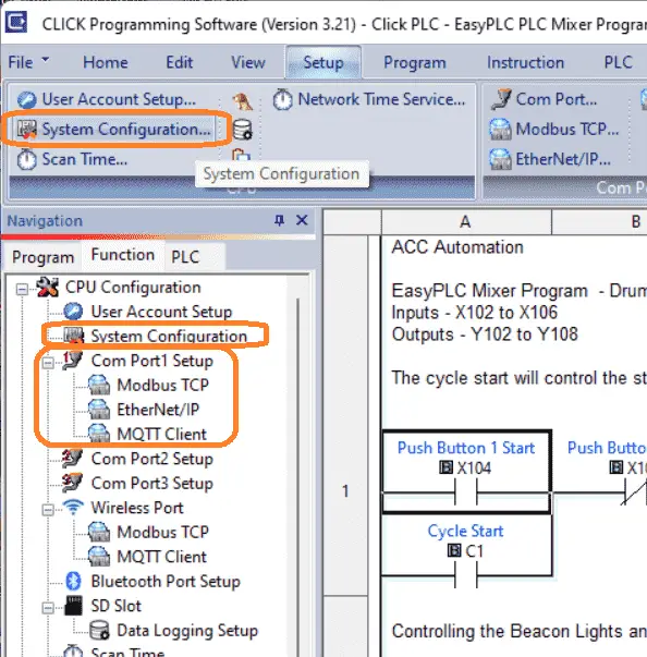 After calling up the system configuration, double-click on the communication port to display the settings. You can also call this directly by selecting the Com Port1 Setup.
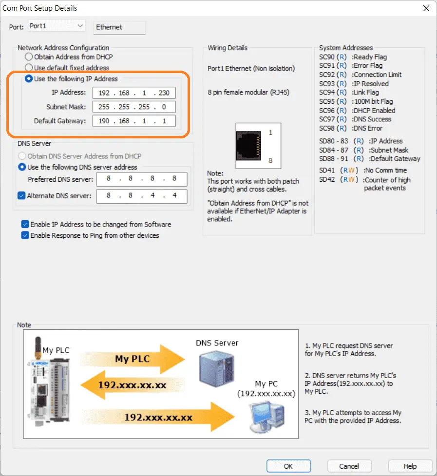 A static (fixed) IP address is used on the network to ensure that we know where the PLC is after power interruptions. Make a note of this address so we can enter the information in the EasyPLC simulator.
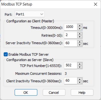 Select Modbus TCP under the port settings to display the Modbus settings. This is enabled on port 502 as the default for the Click PLC.
Save and transfer the PLC program to the Click Plus PLC. Ensure that the PLC is in Run mode.
Watch the video below to see this PLC program in action
Test the program: (Step 5 – EasyPLC Mixer)
We will be using Modbus TCP on our Click Plus PLC to communicate to the EasyPLC Machine Simulator.
Call up the mixer machine simulator in start mode.
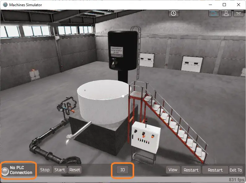 The status of the machine simulator will be along the bottom of the screen. Currently, we have no PLC connected. Select IO Drivers on the bottom middle of the screen.
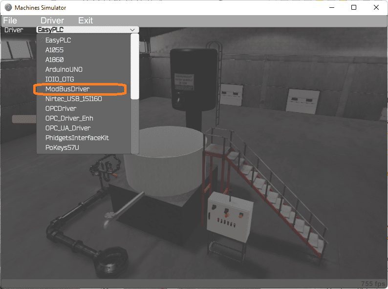 The EasyPLC driver is selected by default. Select the down arrow on the driver’s name. Under the driver pull-down menu, select “ModBusDriver”.
 This driver will communicate Modbus TCP (Ethernet) and Modbus RTU (Serial).
Select the configure button.
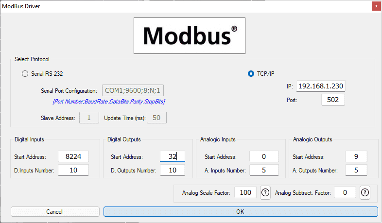 We can now enter the information for our Modbus driver. Select TCP/IP. This really means the Ethernet port on the computer will communicate to the PLC.
The digital inputs from MS to the Click PLC will be Y101 to Y107. This will start at address 8224 due to the offset of 1. Digital outputs from MS to the Click PLC will be X101 to X108. This will start at address32 due to the offset of 1. We are not using the analog input or output in the mixer machine.
Select the OK button.
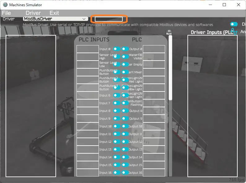
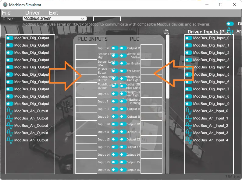 You will now see the inputs and outputs that we have specified for the Modbus driver. We can now manually assign the driver outputs to the PLC inputs and the driver inputs to the PLC outputs. However, the automatic assignment works well and will save you time.
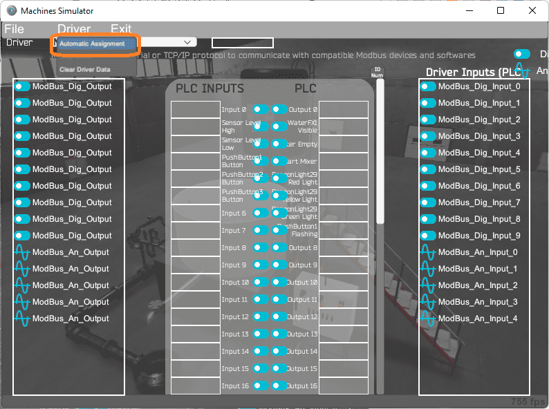 Select Automatic Assignment from the driver option in the main menu.
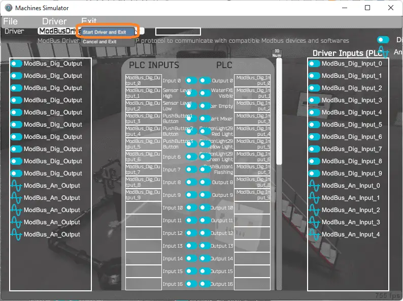 This will automatically assign the PLC IO to the Machine Simulator IO. Select start driver and exit from the main menu.
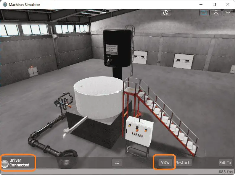 You will see on the bottom left side of the window that the driver is communicating to the PLC by the green light. Select view IO to see the input and output status of the machine simulator.
 Ensure that the PLC is in run mode. We can see the operation of our industrial process mixer. Select the start push button on the control panel.
 The digital inputs and outputs of the MS will correspond to the PLC controller.
 Using Machine Simulator (MS) to test the program will ensure that our program works.
Easy PLC machine simulator has a time frame that you can speed up or slow down the process to help you troubleshoot.
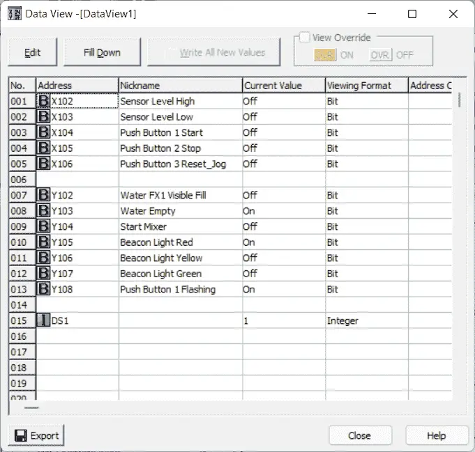
 Using the Data View window of the Click PLC programming software we can also watch the inputs and output operations.
 Watch the video below to see this on the operation.
Download the Click PLC sample program, flow chart, and diagram here.
Watch the video below to see the five steps of program development applied to the industrial process mixer. The machine simulator is one of the best applications to help you learn PLC programming.
EasyPLC Software Suite is a complete PLC, HMI, and Machine Simulator Software package. This PLC learning package includes the following:
Easy PLC – PLC Simulation will allow programming in Ladder, Grafcet, Logic Blocks, or Script.
HMI System – Easily create a visual human-machine interface (HMI)
Machine Simulator – A virtual 3D world with real-time graphics and physical properties. PLC programs can be tested using EasyPLC or through other interfaces. (Modbus RTU, TCP, etc.)
Machine Simulator Lite – Designed to run on Android Devices.
Machine Simulator VR – Virtual Reality comes to life so you can test, train or practice your PLC programming.
Purchase your copy of this learning package for less than $75 USD for a single computer install, or less than $100 USD to allow different computers.
Receive 10% off the price by typing in ACC in the comment section when you order. http://www.nirtec.com/index.php/purchase-price/
Learn PLC programming the easy way. Invest in yourself today.
Watch on YouTube: Click PLC – EasyPLC PLC Mixer Programming
If you have any questions or need further information, please contact me.
Thank you,
Garry
If you’re like most of my readers, you’re committed to learning about technology. Numbering systems used in PLCs are not difficult to learn and understand. We will walk through the numbering systems used in PLCs. This includes Bits, Decimals, Hexadecimal, ASCII, and Floating Points.
To get this free article, subscribe to my free email newsletter.
Use the information to inform other people how numbering systems work. Sign up now.

The ‘Robust Data Logging for Free’ eBook is also available as a free download. The link is included when you subscribe to ACC Automation.