Automated car parking is a great way to learn PLC programming. It is easily understood how this system is to function and operates. The 3D graphics on the machine simulator are good for visually seeing this interaction between the PLC and the virtual machine.
Using the five steps to PLC programming development, we will determine what must be done, look at the inputs and outputs, develop the sequence of operation, program the automated car parking, and test our program. We will be programming with the free Do-More Designer PLC software. The program will use a sequencing method to demonstrate how the logic can be implemented. Bit manipulation will also be done using the encode and move bit instructions. Each vehicle location on the different levels will have to be addressed so that we know if that spot is empty or occupied.
The EasyPLC machine simulator is part of the EasyPLC Software Suite. This package is an excellent way to learn PLC programming without the worry of damaging equipment. The Easy machine simulator will communicate Modbus TCP with the Do-More Designer PLC simulator. This part will review the first three steps of PLC program development using the parking cars simulator. Let’s get started.
Learn PLC programming the easy way. See below for a 10% discount on this cost-effective learning tool. Invest in yourself today.
Previously we have done the following:
Easy PLC Installing the Software – Video
EasyPLC Software Suite – Quick Start – Video
Click PLC – Easy Transfer Line Programming – Video
Productivity PLC Simulator – Chain Conveyor MS – Video
Do-More PLC – EasyPLC Box Selection Program – Video
Click PLC EasyPLC Gantry Simulator – Video
Click PLC Simple Conveyor EasyPLC – Video
EasyPLC Paint Line Bit Shift – BRX Do-More PLC – Video
Click PLC – EasyPLC PLC Mixer Programming – Video
Click PLC EasyPLC Warehouse Stacker Example – Video
– Operation Video
EasyPLC Machine Simulator Productivity PLC Robotic Cell – Video
EasyPLC Simulator Robotic Cell Click PLC – Video
EasyPLC Simulator Robotic Cell BRX Do-More PLC – Video
– EasyPLC Factory Editor Robotic Cell Additions Video
4 Way Traffic Light PLC Program EasyPLC – Video
Rock Crusher Plant EasyPLC BRX Do-More – Video
Freight Carrier Weighing and Distribution EasyPLC – Video
EasyPLC Machining Center Loading Robots – Video
EasyPLC Palletizing Robot Programming Click PLC – Video
EasyPLC Machine Editor – Design a Simulation – Video
PLC Programming Mixing Tank – EasyPLC / Do-More – Video
EasyPLC Solder Robot PLC Programming – Video
PLC Programming – A Tutorial for Beginners – Video
Define the task: (Step 1 – Parking Cars Simulator)
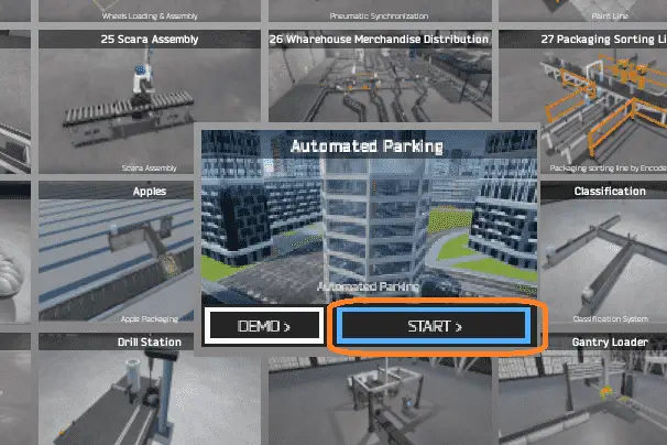
The first step of PLC program development is determining what must be done. A PLC programmer must know everything about the machine before programming. Start the EasyPLC Machine Simulator (MS). Select the start button on the main page or select machines from the main menu on the top of the machines simulator window.
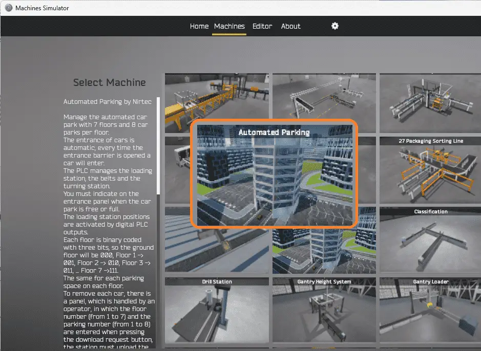
All the available machines will now be displayed. Click on the “Automated Parking.” This is the machine that we will be programming. To the left of the screen, information will be displayed. This will indicate what the machine needs to do and the inputs and outputs required for the program.
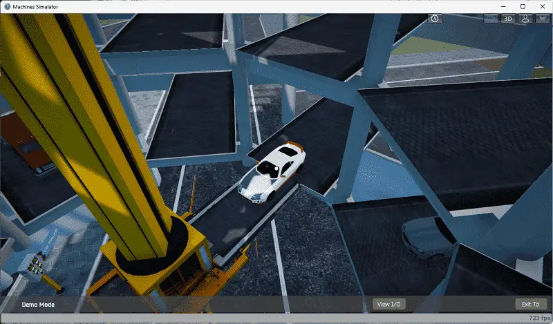
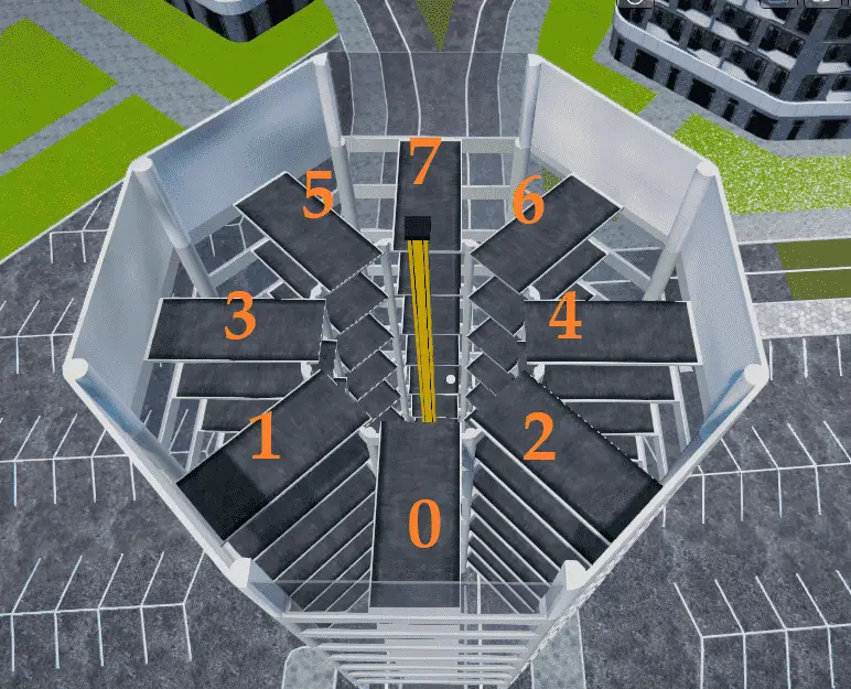
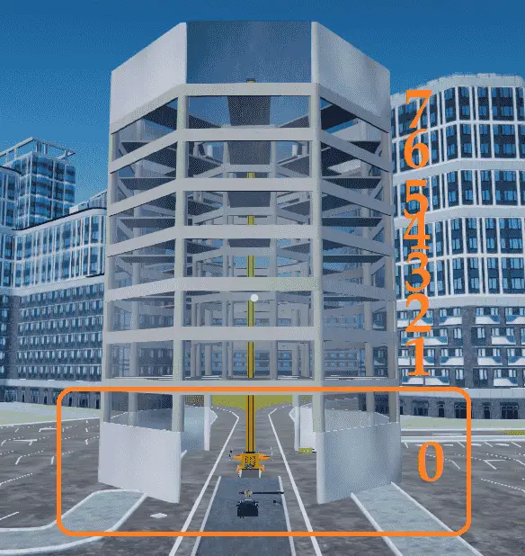
Manage the automated car park with seven floors and eight car parks per floor. The entrance of cars is automatic; every time the entrance barrier is opened, a car will enter. You must indicate when the car park is free or full on the entrance panel. The PLC manages the loading station, the belts, and the turning station. Digital PLC outputs activate the loading station positions. Each floor is binary coded with three bits so that the ground floor will be 000, floor 1 001, floor 2 010, floor 3 011, to floor 7 111. The same coding will work for each parking space on each floor.
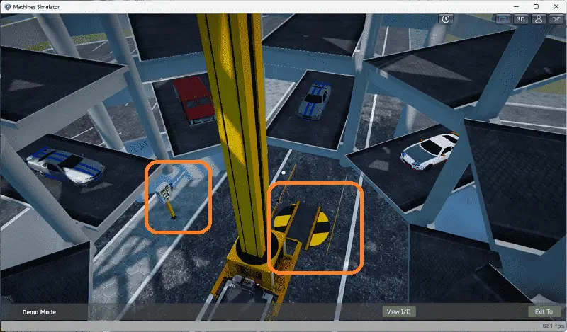
To remove each car, there is a panel that is handled by an operator, in which the floor number (1 to 7) and the parking number (1 to 8) are entered when pressing the download request button; the station must unload the car and place it in the turning station to return it in the correct position. Once the vehicle is out of the turning station, the car will exit automatically.
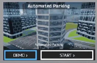
The machine simulator has a demo mode for the built-in machines. Select the demo mode for “Automatic Parking.” This will allow you to watch the operation of the automatic parking.
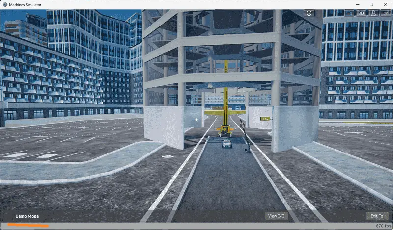
The demo mode will operate, showing you the basics of operation.
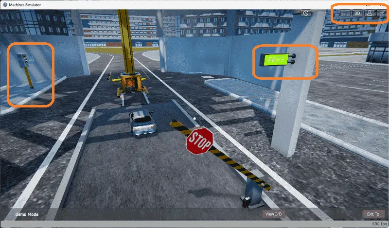
Move around the 3D virtual environment. Three icons on the top of the window will allow you to move around this 3D environment. The first icon is the default selection. This will enable you to move around without bumping into the components. The first-person mode will mimic a person in your 3D learning world. The last icon will automatically show you around this virtual environment.
Once we understand what must be done, we can move on to the next development step in the PLC program.
Define the Inputs and Outputs: (Step 2 – Parking Cars Simulator)
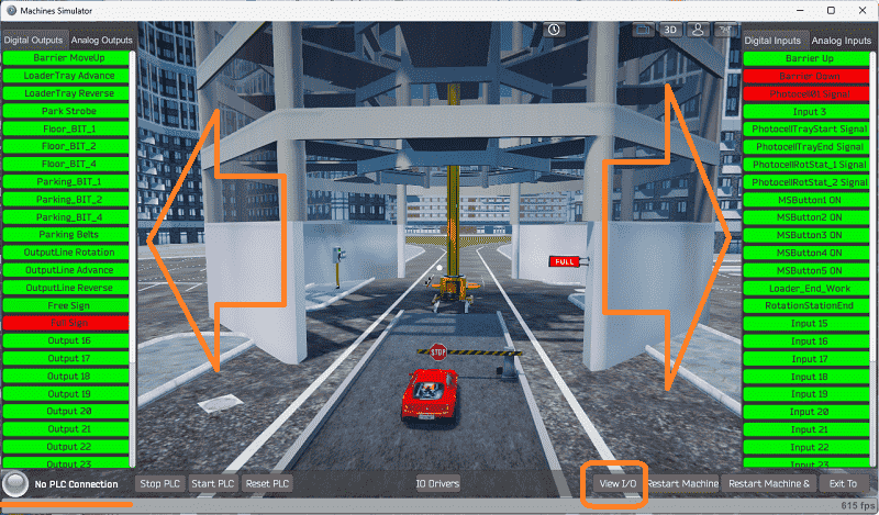
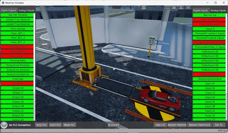
The View IO at the bottom of the machine simulator window will display the inputs and outputs required for this vehicle parking lot. While still in demo mode, you can see the operation of the digital inputs and outputs.
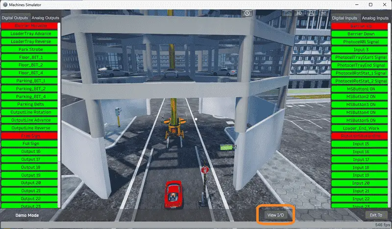
The EasyPLC automatic parking will require 16 digital outputs and 15 digital inputs.
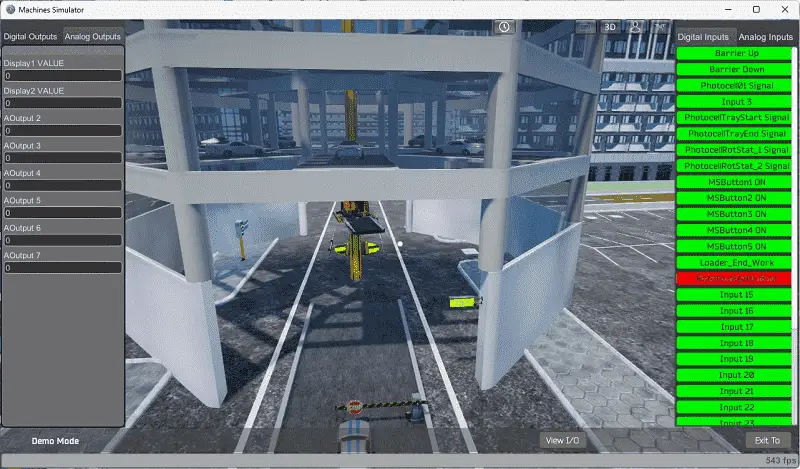
This will also require two analog outputs to display the selected parking level and the spot to request a vehicle.
Start the machine in Start mode. If you are unsure what output or input is doing, we can manually control them.
Select the View IO on the bottom middle of the machine simulator window. You can manually run the parking car simulator application without any control or PLC connection.
Clicking on the left-side outputs will allow you to turn them on manually. You can then monitor the right-side inputs to see their operation. The restart button on the bottom of the machine simulator window will reset the scene back to the start.
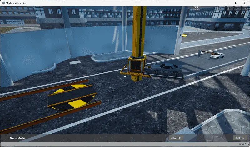
The car loading on the elevator conveyor can be done by selecting the loader tray advance.
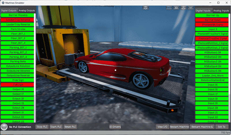
The floor number and parking bit locations are selected by binary code. In this case, we are choosing floor one parking location 0. The park strobe will then move the conveyor to the appropriate spot. Once the conveyor has moved, the loader end work bit will indicate it has arrived at the location.
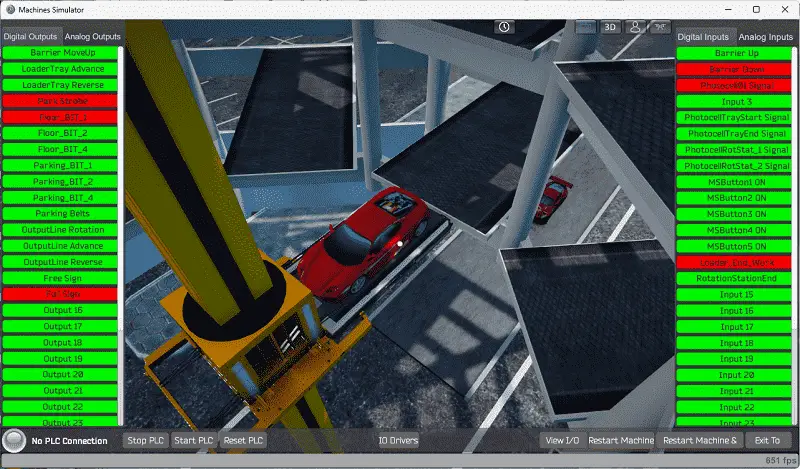
Selecting the parking belts and the loader tray advance or reverse will move the vehicle in and out of a parking location.
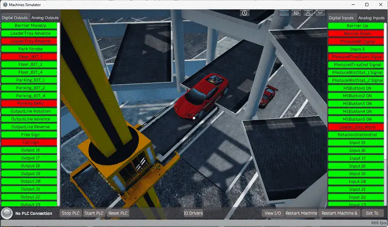
Selecting floor 0 with parking spot seven will return the elevator to the unload output station.
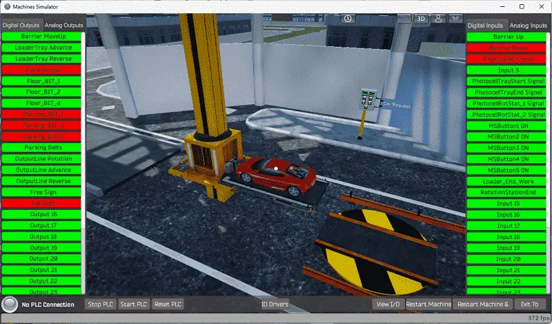
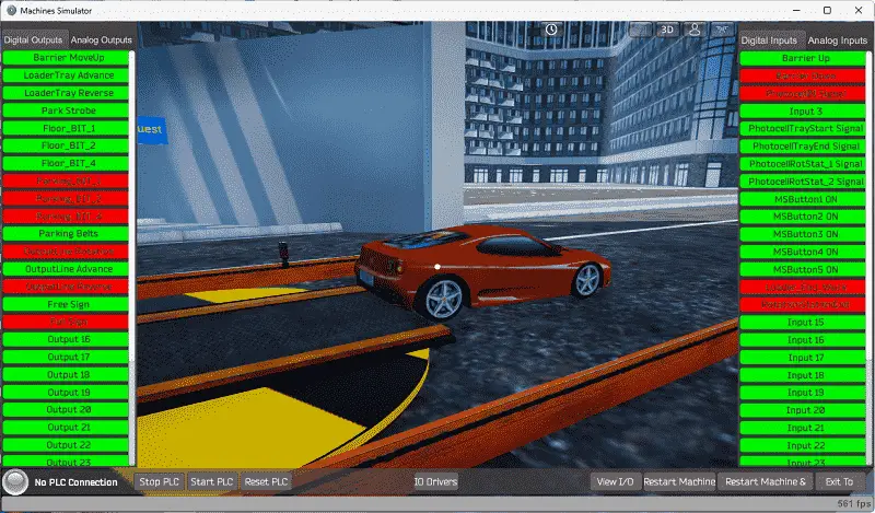
The output station advance with the loader tray reverse will place the vehicle on the rotation station. Sensors will determine when to stop the conveyors.
The output rotation will turn the car around to point it in the correct position. Selecting the output reverse will move the vehicle out of the parking lot.
The EasyPLC machine simulator will allow you to program and make mistakes without the destruction of property or equipment.
Note: You can select the restart machine button to reset everything back to the original location.
Before programming, you must know the function and operation of each input and output.
The following table will define the inputs and outputs (IO) and Modbus addresses in the Do-More Designer Simulator PLC we will use for this program.
| Digital Type | Description | Do-More PLC Modbus Address | Machine Simulator Modbus Address |
| PLC Output – MS Input | Barrier Move Up | MI1 – 10001 | 0 |
| PLC Output – MS Input | Loader Tray Advance | MI2 – 10002 | 1 |
| PLC Output – MS Input | Loader Tray Reverse | MI3 – 10003 | 2 |
| PLC Output – MS Input | Park Strobe | MI4 – 10004 | 3 |
| PLC Output – MS Input | Floor_Bit_1 | MI5 – 10005 | 4 |
| PLC Output – MS Input | Floor_Bit_2 | MI6 – 10006 | 5 |
| PLC Output – MS Input | Floor_Bit_4 | MI7 – 10007 | 6 |
| PLC Output – MS Input | Parking_Bit_1 | MI8 – 10008 | 7 |
| PLC Output – MS Input | Parking_Bit_2 | MI9 – 10009 | 8 |
| PLC Output – MS Input | Parking_Bit_4 | MI10- 10010 | 9 |
| PLC Output – MS Input | Parking Belts | MI11 – 10011 | 10 |
| PLC Output – MS Input | Output Rotation | MI12 – 10012 | 11 |
| PLC Output – MS Input | Output Advance | MI13 – 10013 | 12 |
| PLC Output – MS Input | Output Reverse | MI14 – 10014 | 13 |
| PLC Output – MS Input | Free Sign | MI15 – 10015 | 14 |
| PLC Output – MS Input | Full Sign | MI16- 10016 | 15 |
| PLC Input – MS Output | Barrier Up | MC1 – 1 | 0 |
| PLC Input – MS Output | Barrier Down | MC2 – 2 | 1 |
| PLC Input – MS Output | Photocell 01 Signal | MC3 – 3 | 2 |
| PLC Input – MS Output | Input 3 | MC4 – 4 | 3 |
| PLC Input – MS Output | Photo Tray Start | MC5 – 5 | 4 |
| PLC Input – MS Output | Photo Tray End | MC6 – 6 | 5 |
| PLC Input – MS Output | Photo Rot Stat 1 | MC7 – 7 | 6 |
| PLC Input – MS Output | Photo Rot Stat 2 | MC8 – 8 | 7 |
| PLC Input – MS Output | MS Button 1 (Floor +) | MC9 – 9 | 8 |
| PLC Input – MS Output | MS Button 2 (Floor -) | MC10 – 10 | 9 |
| PLC Input – MS Output | MS Button 3 (Spot +) | MC11 – 11 | 10 |
| PLC Input – MS Output | MS Button 4 (Spot -) | MC12 – 12 | 11 |
| PLC Input – MS Output | MS Button 5 (Request Car) | MC13 – 13 | 12 |
| PLC Input – MS Output | Loader End Work | MC14 – 14 | 13 |
| PLC Input – MS Output | Rotation Station End | MC15 – 15 | 14 |
| PLC Analog Output – MS Analog Input | Display 1 Value – Level Request | MHR1 – 1 | 0 |
| PLC Analog Output – MS Analog Input | Display 2 Value – Parking Spot Location | MHR2 – 2 | 1 |
Note: The machine simulator will be offset by one on the Modbus Addresses. See the video below for the demo mode and determining inputs and outputs.
Develop a logical sequence of operation: (Step 3 – Parking Cars Simulator)
A flow chart, sequence table, or detailed sequence description is used to understand the process that needs to be controlled.
You may think this is like step 1, but it will go into more detail and utilize all the inputs and outputs that need to be programmed.
It must also answer questions like the following:
What happens when electrical power or pneumatic air is lost? What happens when the input/output devices fail? Do we need redundancy?
This step is where you will spend most of your time. Understanding everything about the operation will save you time. It will help prevent you from continuously re-writing the PLC program logic. Knowing all these answers upfront is vital in developing the PLC program. Our system will become simple to program once we understand the logical sequence. This will assist us in writing the ladder logic program.
Reviewing the inputs and output of the previous step has given us a good idea of how the logical sequence will work. We will use a drum instruction to control the overall sequence of the automatic parking simulator. The drum will turn on individual bits at a time so we can perform only the selected logic before moving on to the next. Here is the sequence of steps to be completed.
1 – Auto initialize – This will ensure that the elevator waits for the following vehicle to load from the entrance.
2 – Load Auto – This will open the barrier until it is in the open position. The car will automatically enter the parking lot. It will close when the sensor does not detect a car at the barrier. The elevator loading tray will advance to load the vehicle. Once the loading tray end signal is received, then the loading is complete.
3 – Move to Park Location – Determine the park location and move the elevator to this location.
4 – Unload the vehicle – This will unload the car in the parking location.
If a request is not made to return a vehicle, reset to the beginning of this sequence. A vehicle must be present in the parking level and location for a request to be valid. If a request has been made, then continue with the following steps.
5 – Return Load Auto – Move the elevator to the return level and parking location.
6 – Move Unload Auto – Move the elevator with the car to the unloading location.
7 – Return Unload Auto – Unload the car at the unload station.
8 – Rotate the vehicle to point in the correct orientation.
9 – Sent the vehicle out of the parking location.
10 – Rotate the unload station back and reset the sequence back to the beginning
Keeping track of the car parking locations will be done with bits in specific registers.
We have seven levels of parking with 8-bit locations (0 to 7) for each level. Memory retentive registers will be used to track the levels and bits. V1 to V7 will represent the levels. V1:0 to V1:7 is part of register V1 and will represent the parking locations for level 1. The rest of the levels will be similar.
A PLC programmer must know how everything about the sequence and operation of the machine before programming.
Ask questions or View existing documentation to ensure you know the logical steps to the machine’s operation.
In the next part of this post, we will write the PLC ladder logic program and test this with the simulators.
Watch the video below to see the first three steps of program development applied to the simple conveyor. The machine simulator is one of the best applications to help you learn PLC programming.
EasyPLC Software Suite is a complete PLC, HMI, and Machine Simulator package. This PLC learning package includes the following:
Easy PLC – PLC Simulation allows programming in Ladder, Grafcet, Logic Blocks, or Script.
HMI System – Easily create a visual human-machine interface (HMI)
Machine Simulator – A virtual 3D world with real-time graphics and physical properties. PLC programs can be tested using EasyPLC or through other interfaces. (Modbus RTU, TCP, etc.)
Machine Simulator Lite – Designed to run on Android Devices.
Machine Simulator VR – Virtual Reality comes to life so you can test, train or practice your PLC programming.
Purchase your copy of this learning package for less than USD 75 for a single computer install or less than USD 100 to allow different computers.
Receive 10% off the price by typing in ACC in the comment section when you order. http://www.nirtec.com/index.php/purchase-price/
Learn PLC programming the easy way. Invest in yourself today.
Watch on YouTube: Parking Cars Simulator PLC Programming Part 1
If you have any questions or need further information, please get in touch with me.
Thank you,
Garry
If you’re like most of my readers, you’re committed to learning about technology. Numbering systems used in PLCs are not challenging to learn and understand. We will walk through the numbering systems used in PLCs. This includes Bits, decimals, Hexadecimal, ASCII, and Floating points.
To get this free article, subscribe to my free email newsletter.
Use the information to inform other people how numbering systems work. Sign up now.

The ‘Robust Data Logging for Free’ eBook is also available for free download. The link is included when you subscribe to ACC Automation.