We began using the five steps to PLC programming development in part 1 for the parking cars simulator. This involved determining what must be done, looking at the inputs and outputs, and developing the sequence of operation. Automated car parking is a great way to learn PLC programming. It is easily understood how this system is to function and operates. The 3D graphics on the EasyPLC machine simulator are good for visually seeing this interaction between the PLC and the virtual machine.

We will continue programming the automated car parking and testing our program. We will be programming with the free Do-More Designer PLC software. The EasyPLC machine simulator is part of the EasyPLC Software Suite. This package is an excellent way to learn PLC programming without the worry of damaging equipment. The Easy machine simulator will communicate Modbus TCP with the Do-More Designer PLC simulator. Let’s start with the second part of our parking cars simulator PLC programming.
Learn PLC programming the easy way. See below for a 10% discount on this cost-effective learning tool. Invest in yourself today.
Previously we have done the following:
Easy PLC Installing the Software – Video
EasyPLC Software Suite – Quick Start – Video
Click PLC – Easy Transfer Line Programming – Video
Productivity PLC Simulator – Chain Conveyor MS – Video
Do-More PLC – EasyPLC Box Selection Program – Video
Click PLC EasyPLC Gantry Simulator – Video
Click PLC Simple Conveyor EasyPLC – Video
EasyPLC Paint Line Bit Shift – BRX Do-More PLC – Video
Click PLC – EasyPLC PLC Mixer Programming – Video
Click PLC EasyPLC Warehouse Stacker Example – Video
– Operation Video
EasyPLC Machine Simulator Productivity PLC Robotic Cell – Video
EasyPLC Simulator Robotic Cell Click PLC – Video
EasyPLC Simulator Robotic Cell BRX Do-More PLC – Video
– EasyPLC Factory Editor Robotic Cell Additions Video
4 Way Traffic Light PLC Program EasyPLC – Video
Rock Crusher Plant EasyPLC BRX Do-More – Video
Freight Carrier Weighing and Distribution EasyPLC – Video
EasyPLC Machining Center Loading Robots – Video
EasyPLC Palletizing Robot Programming Click PLC – Video
EasyPLC Machine Editor – Design a Simulation – Video
PLC Programming Mixing Tank – EasyPLC / Do-More – Video
EasyPLC Solder Robot PLC Programming – Video
PLC Programming – A Tutorial for Beginners – Video
Automated Parking Demo Video
Parking Cars Simulator PLC Programming Part 1 – Video
Establishing Communication between EasyPLC Machine Simulator and Do-More PLC Simulator
Start the Do-more Designer PLC programming software. Connect to the simulator online. PLC Programming – A Tutorial for Beginners is an excellent post on how this is done.
It will cover how to use the Do-more PLC programming software and the EasyPLC machine simulator software.
Once you are connected to the PLC simulator, select System Configuration.
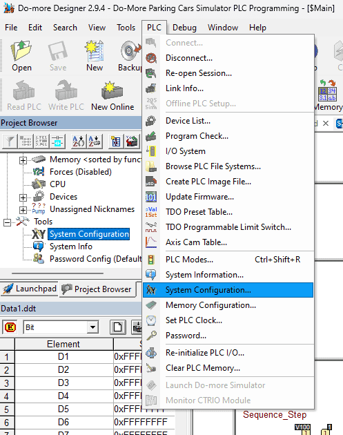
This can be selected under tools in the project browser or on the main menu | PLC | System Configuration…
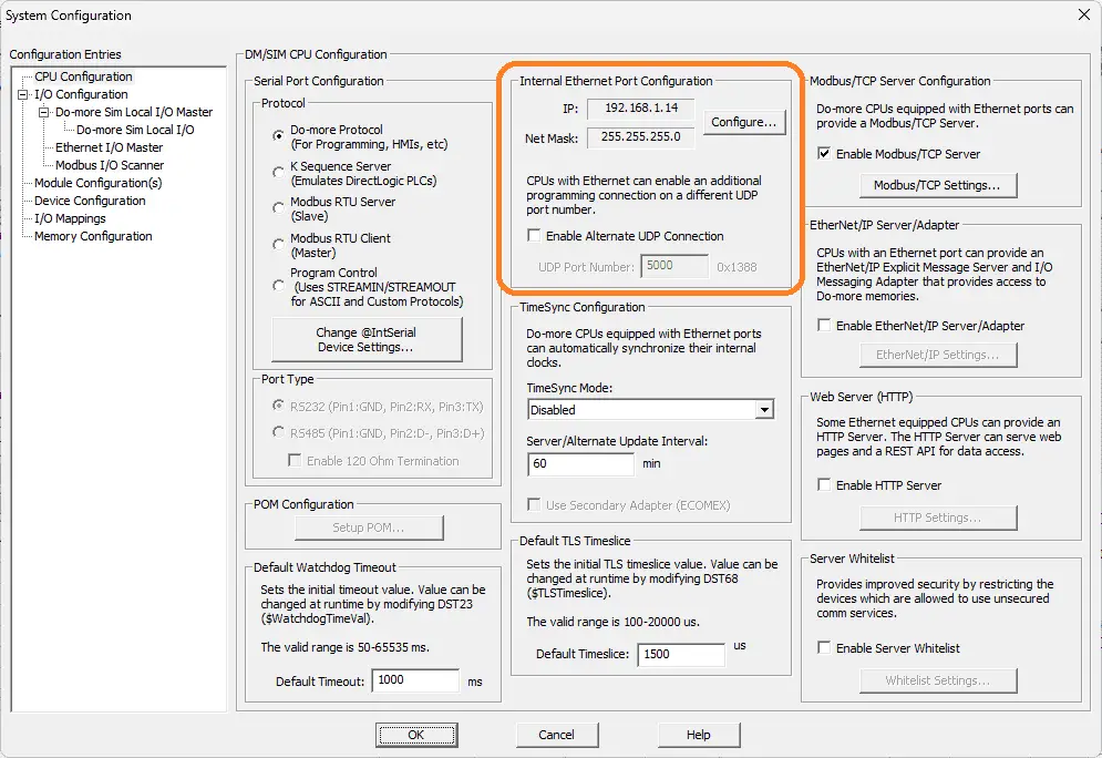
The internal Ethernet port configuration will be displayed for the PLC simulator. Make a note of the IP address of this controller. This would be the same as the computer used for the Do-More Designer software. Remember that this PLC simulator is just like having a separate machine. You have to send and request information from it like it is independent and not virtual.
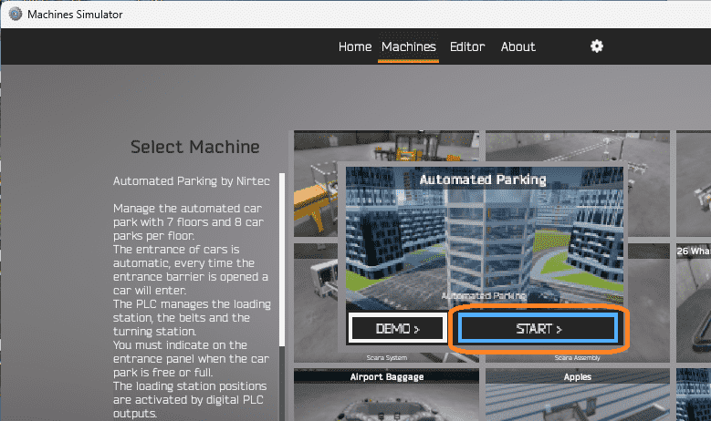
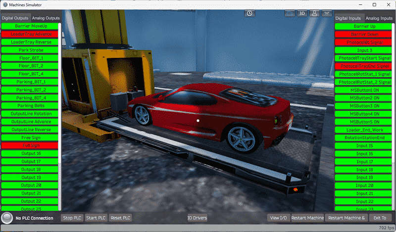
Start the EasyPLC Automatic Parking machine simulator in start mode.
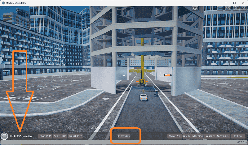
You can see that we have no PLC connected indicated in the bottom left corner. Select IO Drivers on the bottom middle of the screen.
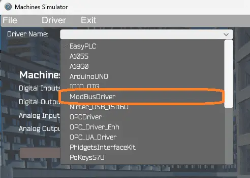
The EasyPLC driver is selected by default. Under the driver pull-down menu, select “ModBusDriver.” This driver will communicate Modbus TCP (Ethernet) and Modbus RTU (Serial). Select the down arrow on the driver’s name.
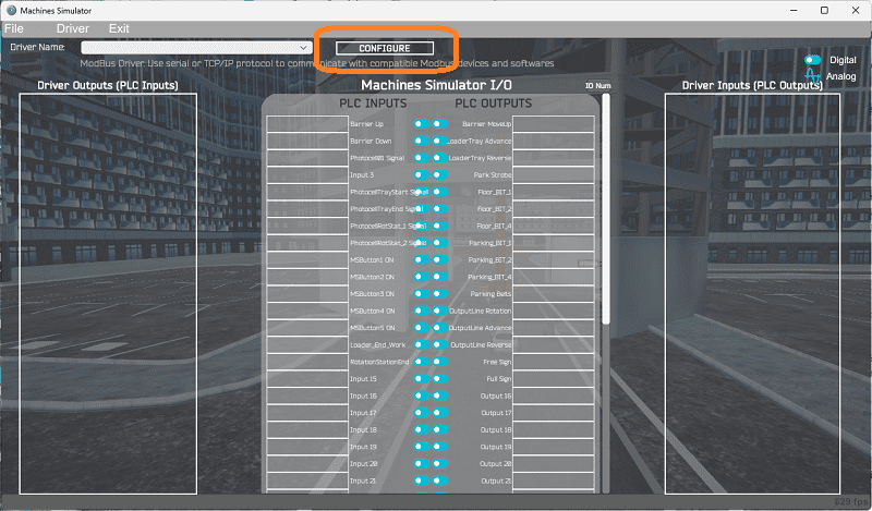
Select the configure button.
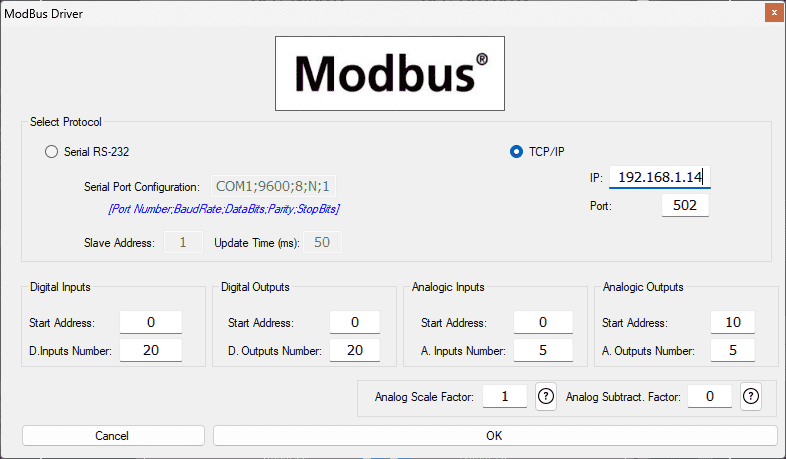
We can now enter the information for our Modbus driver. Select TCP/IP. This means the computer’s Ethernet port will communicate with the PLC.
The digital inputs from MS to the Do-More PLC will start at 100001. This will begin at address 0 due to the offset of 1. Digital outputs from MS to the Do-More PLC will start at 1. This will begin at address 0 due to the offset of 1. Our analog inputs will start at 400001 (MHR1), beginning at address 0. Select the OK button.
The number of inputs and outputs will only matter if all of the number I/O is equal to or greater than the required amount for the EasyPLC simulator machine.
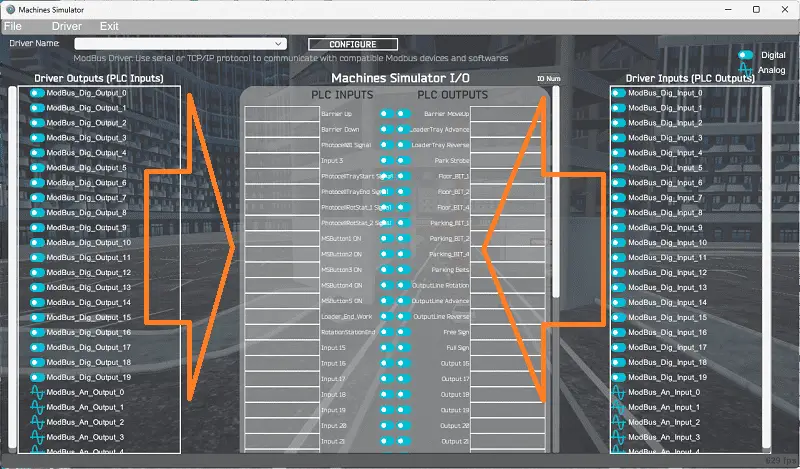
You will now see the inputs and outputs specified for the Modbus driver. We can manually assign the driver outputs to the PLC inputs and the driver inputs to the PLC outputs. However, the automatic assignment works well and will save you time.
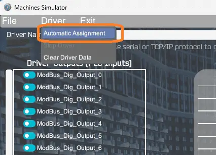
Select Automatic Assignment from the driver option in the main menu.
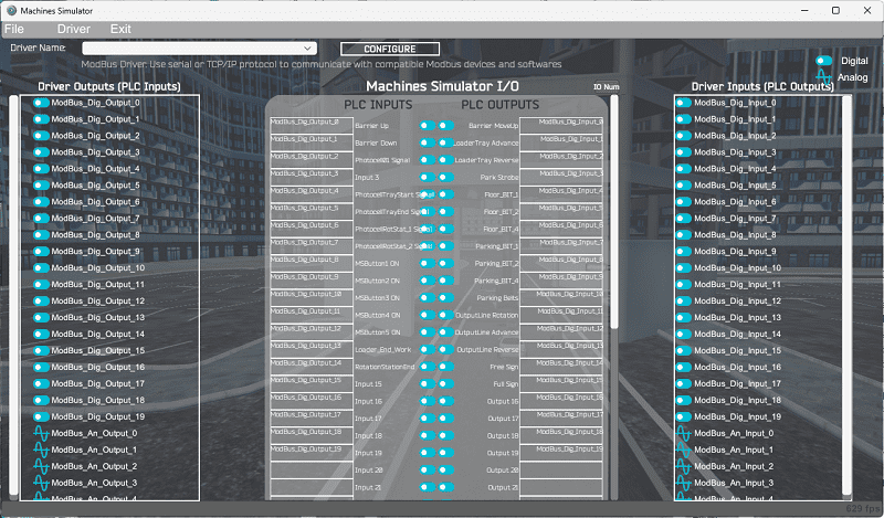
This will automatically assign the PLC IO to the Machine Simulator IO.
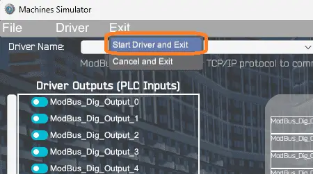
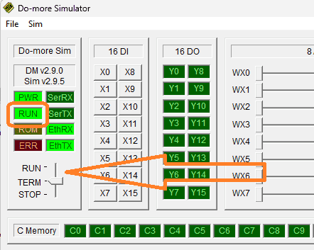
Select start driver and exit from the main menu.
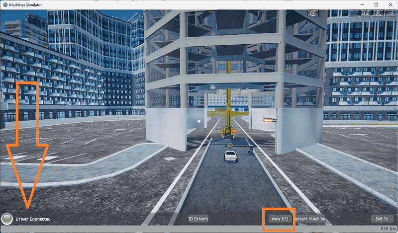
On the bottom left side of the window, you will see that the driver communicates to the PLC with the green light. Select view IO to know the input and output status of the machine simulator.
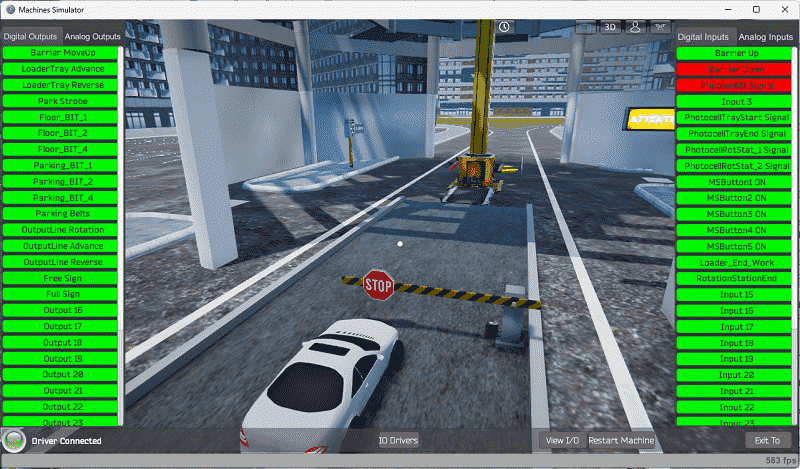
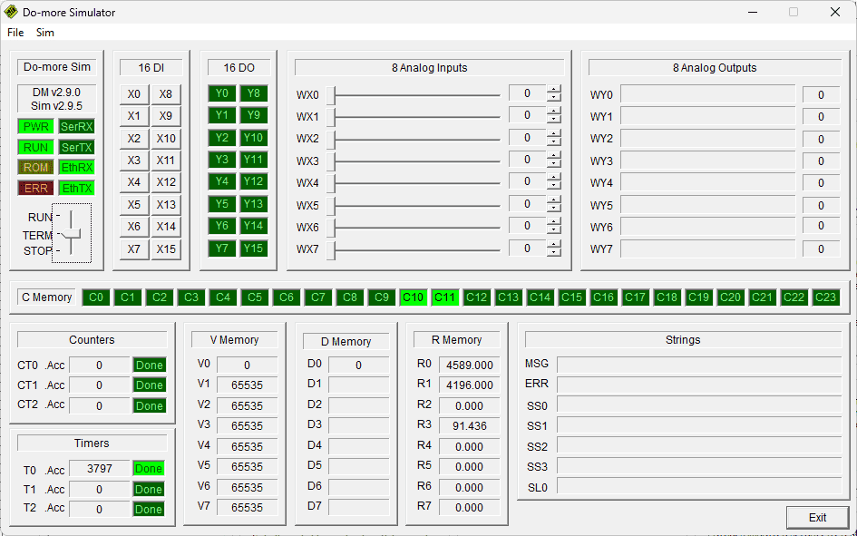
The PLC now has control over the inputs and outputs. We can test the PLC’s inputs and outputs by calling the Data View window from the Do-more designer software. We are ready to move on to the next step and develop our ladder logic program.
Develop the Do-More Designer PLC program: (Step 4 – Parking Cars Simulator)
Writing the ladder logic code for the PLC example will be the next step in our program development. The BRX Do-More Series will provide additional information on the Do-More Designer and PLC Simulator.
Writing PLC ladder logic programs can be done in several ways. Based on the information in part 1 of this example, this is how I would approach the logic.
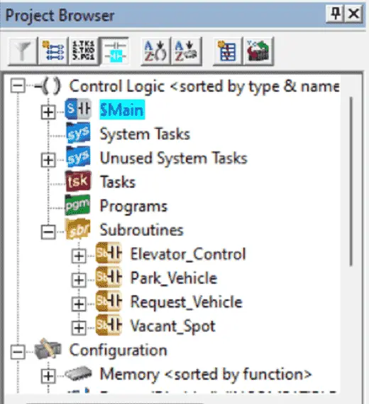
The program is broken up into five different components. The main logic will control the sequencing. “Vacant Spot” will determine the next vacant spot and level. The “Park Vehicle” will handle the parking and return of the vehicle from the different locations. The “Request Vehicle” will control the operator panel (HMI) to return the car. “Elevator Control” will control the movement of the elevator to the different parking locations, loading, and unloading.
Vacant Spot
This subroutine will determine the vacant spot on each floor and determine if the floor is full.
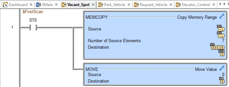
The first scan bit will reset all of the parking spots. This is done by placing one into each of the bits.
V1 – Floor 1 – Bits 0 to 7 – Parking Spots
V2 – Floor 2 – Bits 0 to 7 – Parking Spots
V3 – Floor 3 – Bits 0 to 7 – Parking Spots
V4 – Floor 4 – Bits 0 to 7 – Parking Spots
V5 – Floor 5 – Bits 0 to 7 – Parking Spots
V6 – Floor 6 – Bits 0 to 7 – Parking Spots
V7 – Floor 7 – Bits 0 to 7 – Parking Spots
1 – This means the parking location is empty
0 – This means that a vehicle has been parked
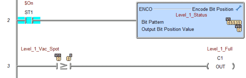
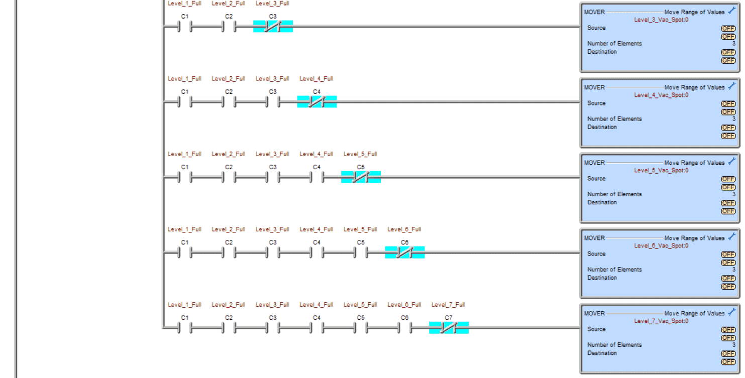
The encode instruction is used to determine the highest bit that is on in the word. If the highest bit is greater or equal to 8, then we know that the floor is full. In this case, floor 1 (V1) has all the spots available, so the output position value is 0 representing the first bit.
This same coding is repeated for each of the other six levels. The output level full bits would be C2 to C7, indicating that the floor is full.
The next rung will determine the current floor and parking spot that is available for parking. This will be placed in V10 and V20, respectfully.
The top floors are done first down to the first level. If a car is requested, the level of the vehicle ordered is placed in V10. This code will keep track of all of the parking locations in the lot.
Main Logic
A drum instruction is used as the main sequencer logic for the program.
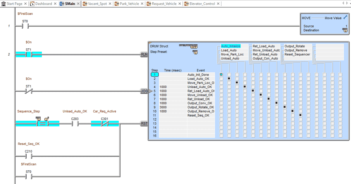
The first scan bit ensures that the drum will reset to step 1. The drum will reset if a car is not requested to be unloaded at step 3. If a vehicle is to be unloaded, the drum will continue to step 11 and reset.
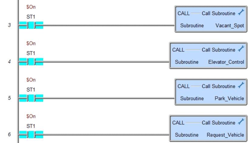
The next four rungs of logic in the main will call up each subroutine. They will control the individual logic of each group.
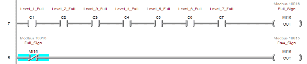
If all of the levels are filled, then the sign is controlled. If not, then the free sign is displayed.
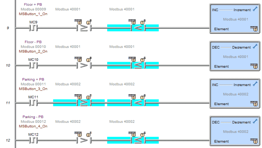
The inputs on the HMI panel for the car request use a one-shot to increment or decrement the floor (MHR1) or parking spot (MHR2). Comparison operators are used to ensure that the values for the floor are between 1 and 7 and that the parking spots are between 0 and 7.
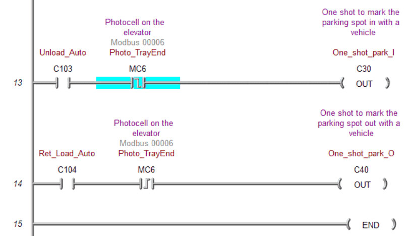
Two one-shots are made to trigger the marking of a parking spot as occupied or not. This will happen when it unloads the automobile into the parking spot or loads the car out.
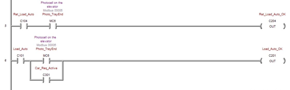
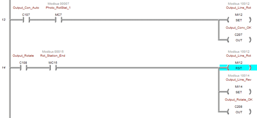
Elevator Control
This will control the elevator for our program.
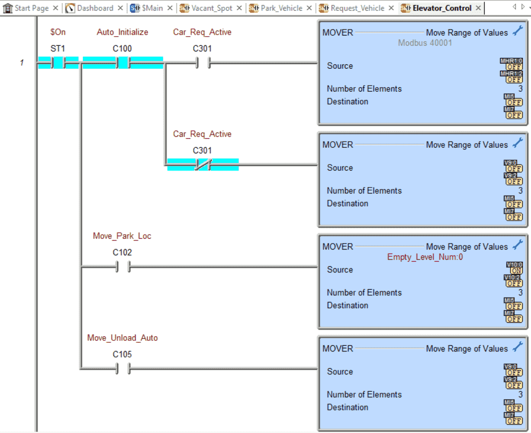
The floor number is determined first. Each step in the drum sequencer that sets the floor number will be in this rung. During the initializing step, if a car is requested, then the level comes from MHR1. If not, then the next vacant spot is used.
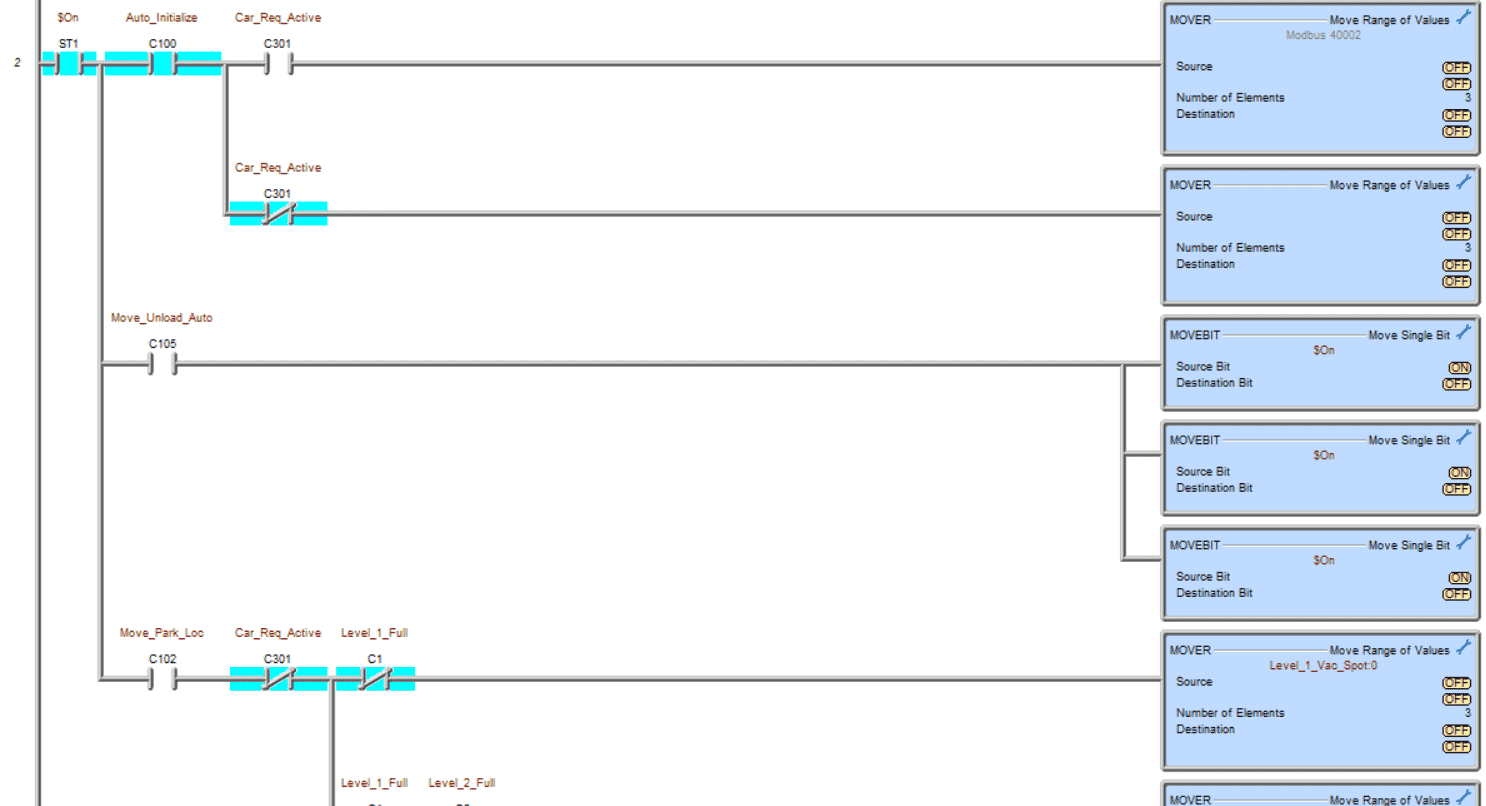
The parking spot is determined next. During the initializing step, if a car is requested, the location comes from MHR2. If not, then the following vacant place is used. The unload location is binary seven which is all bits on.
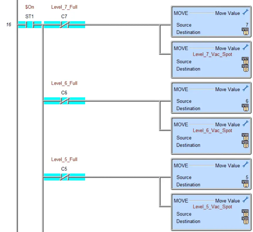
When unloading the vehicle, the level that is not full is done first. This way, if a car is removed from a previous level, it will be replaced first. So the cars are parked from level 1 parking locations 0 to 7 to level 7 parking locations 0 to 7.
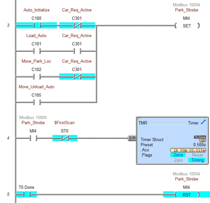
The parking strobe will tell the elevator to move. A timer is set for half a second for the signal of the parking strobe. This will allow the EasyPLC machine simulator to see and activate the signal.
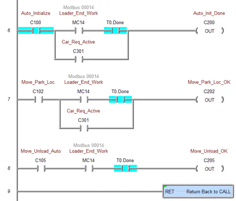
The step complete for the elevator movement is done with the following rungs. If a car is requested, the auto initialize and move to park location is bypassed.
Park Vehicle
This section of the ladder logic code will control the conveyor belts to move the car in and out of the parking lot.
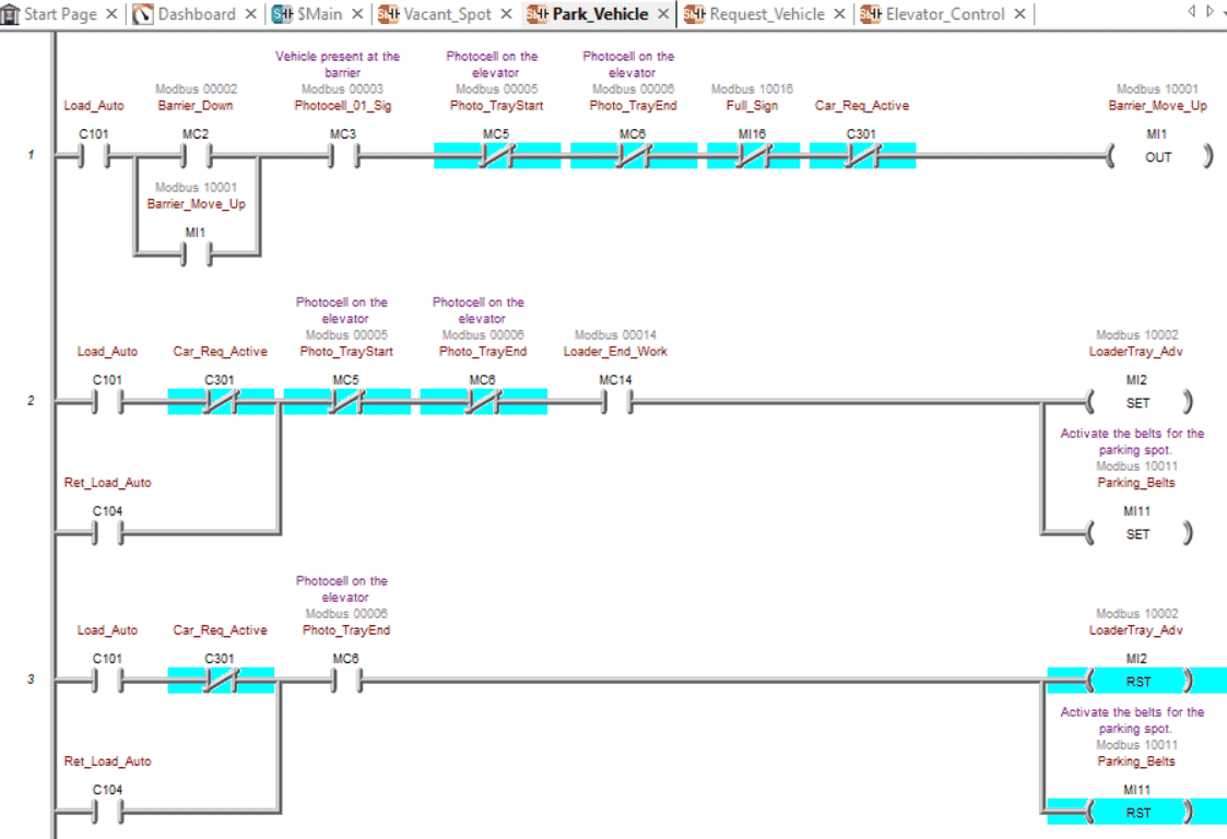
During car loading, if a car is at the barrier and it is down, then we will move it up. This will let the car into the parking lot. Once the photocell at the barrier is not on, the barrier will come down again. The loader tray conveyor will advance so the car will be loaded on the elevator.
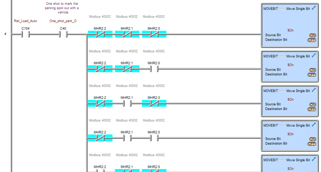
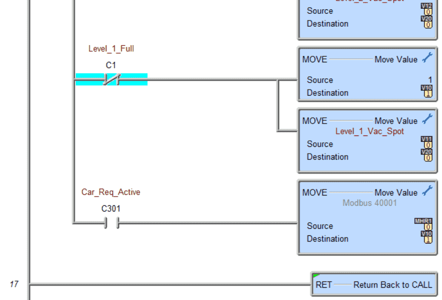
When the vehicle is removed from the parking spot, a one or high bit is placed in its location so that we mark the spot as vacant.
Step reset for the vehicle unloading and loading.
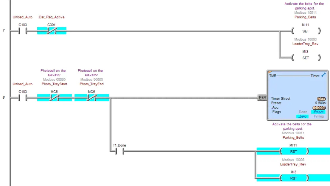
Unload the auto into a parking spot. This will set the conveyors to unload the vehicle into the parking spot. A 1/2-second timer ensures that the car has left the elevator conveyor.
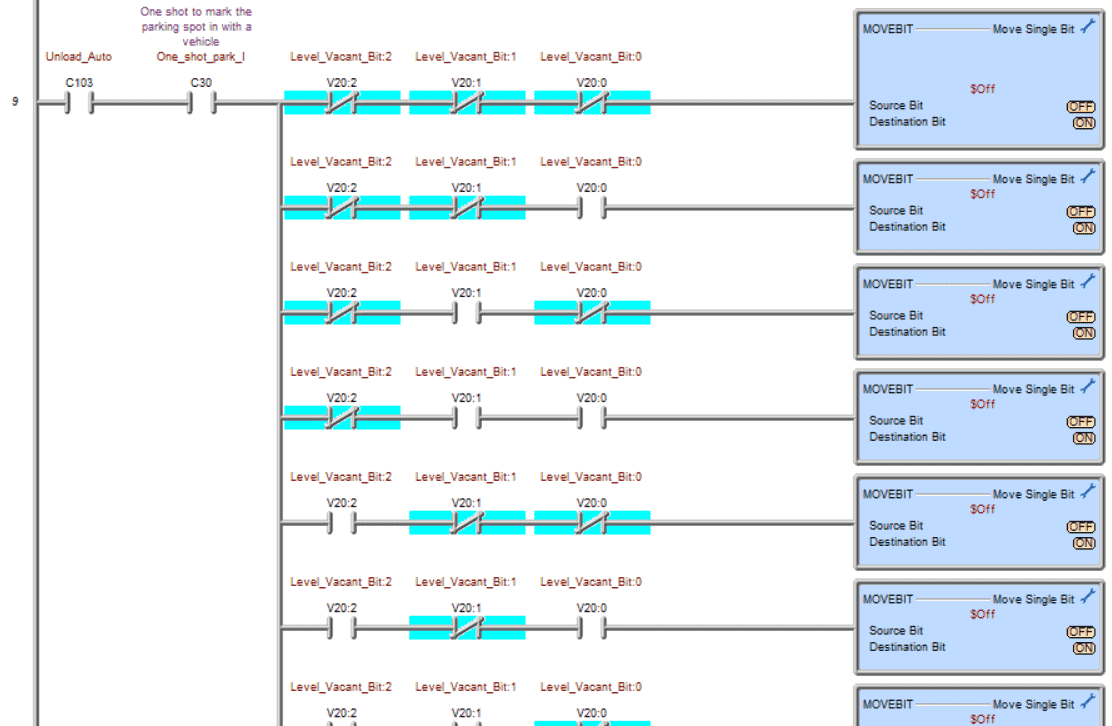
Set the corresponding bit off to indicate a car has been parked in the location. This is determined by binary bit sequencing for the vacant spot on the floor.
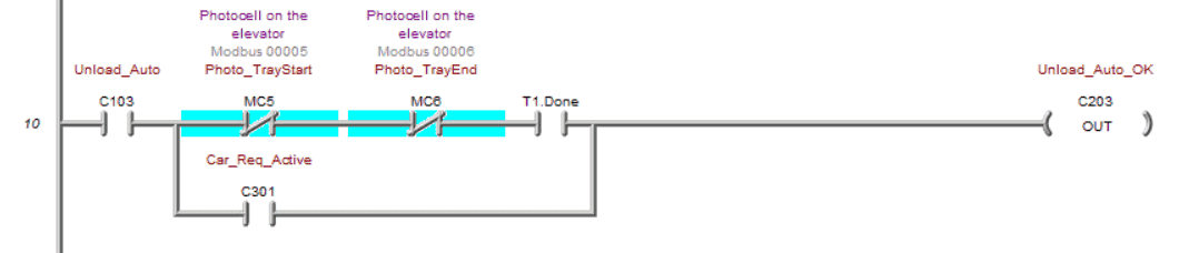
Reset unload auto
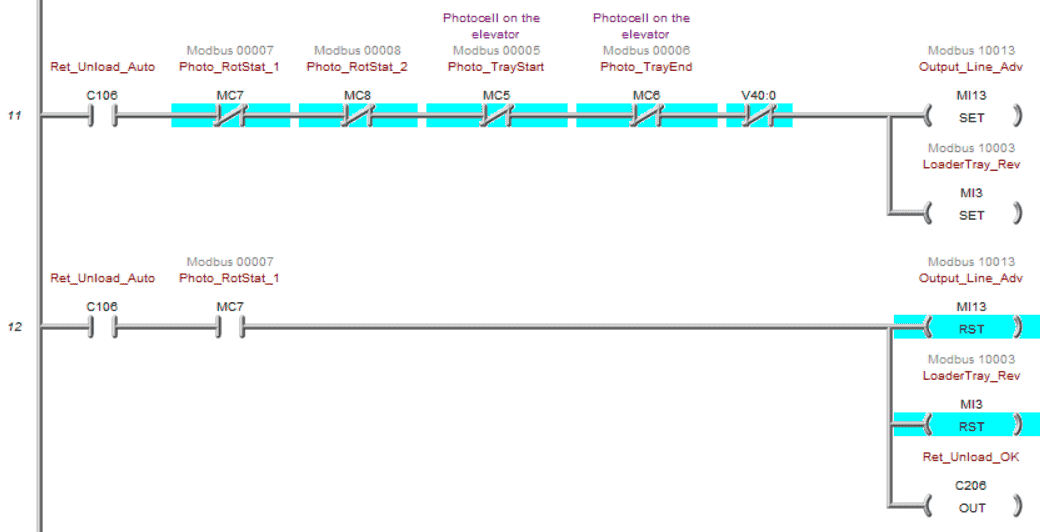
Unload on the unloading station
Rotate and then send out of the parking lot.
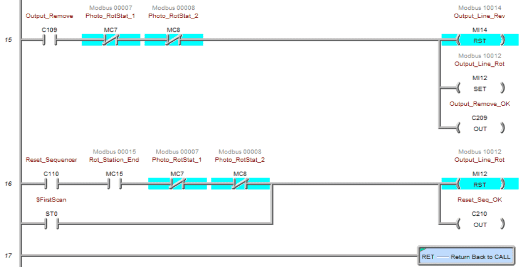
Stop the conveyors and rotate back the turnaround. This is the end of the program sequence steps.
Request Vehicle
The requested vehicle will ensure that the parking spot and level contain a car to unload.
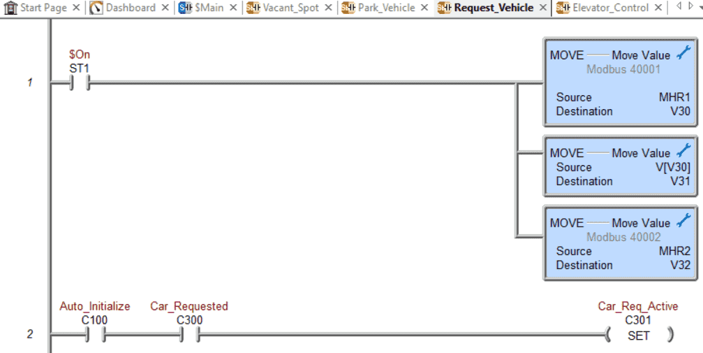
Move the entered parameters into a work area so we can manipulate the bits. V31 will represent the actual parking spots on the floor, and V32 will represent the parking spot selected. The car request becomes active only on the initialization of the sequence.
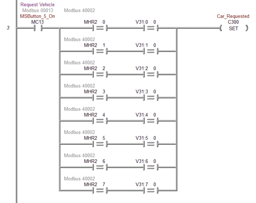
Check to ensure that a vehicle is present. If the parking spot bit is requested and the actual parking spot location is occupied (0), then the car request is valid.
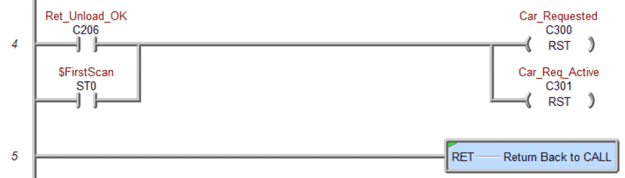
Reset the car request bits after unloading the car from the parking spot or the first scan bit.
Save the program and write to the PLC. Our program is now complete.
Documentation is one of the essential things with PLC programming. Knowing what the program is doing years after you develop the logic can be critical.
On the main menu, select Tools | Documentation Editor… All the elements that have been used in the program are listed. We can assign names to each of them. You can also call the document editor using the Ctrl + D keyboard shortcut.
Watch the video below to see this PLC program in action.
Test the program: (Step 5 – Parking Cars Simulator)
Ensure that the PLC is in run mode. We can see the operation of our automated parking.
Test the program under many conditions. Request a car during each step of the sequence. Is it responding correctly? When an error in the ladder logic is found, simple modifications can be done using online programming with the PLC.
Move around this EasyPLC machine environment and try to account for when sensors fail. This is all a part of program testing.
You may have to rewrite your ladder logic code if something unexpected happens. This may even mean that you will have to change your operation sequence.
To help you practice and learn more, here are a few challenges for this automated parking.
– Add an LED light on the HMI panel to indicate that an invalid parking spot has been entered. This will flash so that the operator will know it has to be corrected.
– Show the number of cars in the parking lot and the available spots.
– Set up manual controls in the 3D environment so a vehicle can be parked or removed from this new manual control panel.
The Do-More PLC Simulator will communicate Modbus TCP. This means we can have remote access to the controller using a separate computer on the network.
– Create a Node-Red application that will log the daily totals of the parking lot in a SQL database.
Let me know how you did in the comments below. These additional exercises will enhance your PLC knowledge and ladder logic programming.
Download the Do-More Designer PLC sample program and EasyPLC Automated Parking program here.
Watch the video below to see the five steps of program development applied to this automated car parking example. The machine simulator is one of the best applications to help you learn PLC programming.
EasyPLC Software Suite is a complete PLC, HMI, and Machine Simulator package. This PLC learning package includes the following:
Easy PLC – PLC Simulation allows programming in Ladder, Grafcet, Logic Blocks, or Script.
HMI System – Easily create a visual human-machine interface (HMI)
Machine Simulator – A virtual 3D world with real-time graphics and physical properties. PLC programs can be tested using EasyPLC or through other interfaces. (Modbus RTU, TCP, etc.)
Machine Simulator Lite – Designed to run on Android Devices.
Machine Simulator VR – Virtual Reality comes to life so you can test, train or practice your PLC programming.
Purchase your copy of this learning package for less than USD 75 for a single computer install or less than USD 100 to allow different computers.
Receive 10% off the price by typing in ACC in the comment section when you order. http://www.nirtec.com/index.php/purchase-price/
Learn PLC programming the easy way. Invest in yourself today.
Watch on YouTube: Parking Cars Simulator PLC Programming Part 2
If you have any questions or need further information, please get in touch with me.
Thank you,
Garry
If you’re like most of my readers, you’re committed to learning about technology. Numbering systems used in PLCs are not challenging to learn and understand. We will walk through the numbering systems used in PLCs. This includes Bits, decimals, Hexadecimal, ASCII, and Floating points.
To get this free article, subscribe to my free email newsletter.
Use the information to inform other people how numbering systems work. Sign up now.

The ‘Robust Data Logging for Free’ eBook is also available for free download. The link is included when you subscribe to ACC Automation.