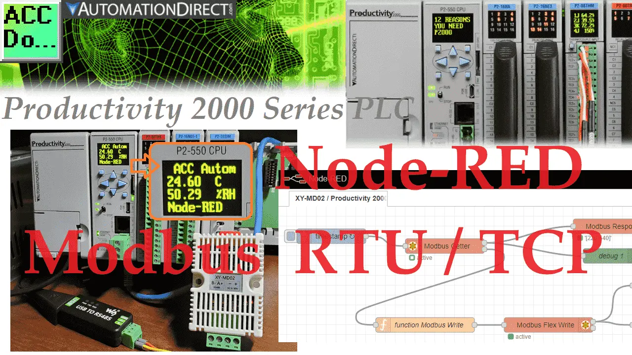
We will now look at communication between the Productivity 2000 PLC (Modbus TCP Server) and Node-RED (Modbus TCP Client). Node-RED is a powerful, adaptable HMI/SCADA (Supervisory Control and Data Acquisition) development package that uses flow programming. Minimal coding is required; you can see the program flow visually. The best thing is that the software is free. We will look at using Node-RED with the Productivity 2000 Series PLC.
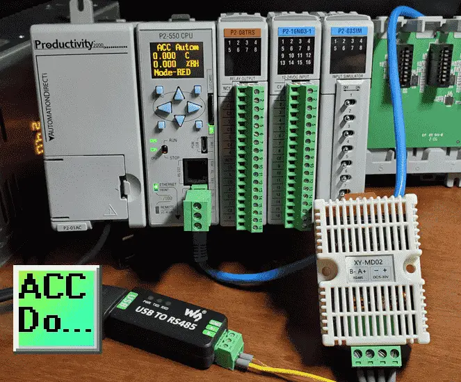
Node-RED will be used to create a single Modbus flow. We will communicate to our XY-MD02 Temperature and Humidity sensor using Modbus RTU on a serial RS485 network. The present values of the sensor will be read. These values will then be written to our Productivity 2000 PLC using an Ethernet Modbus TCP network. These temperature and humidity readings will then be displayed on the P2000 CPU. Let’s get started using Node-RED for Modbus communication.
Previously in this Productivity 2000 series PLC, we have discussed the following:
P2000 Hardware Features – Video
Productivity Suite Software Install – Video
Communication (System Configuration) – Video
First Program – Video
Debug Mode – Video
PLC Program Documentation – Video
PLC CPU Display – Video
PLC Online Programming – Video
PLC Tag Database – Video
Ladder Logic Contacts – Video
Ladder Logic Outputs – Video
Timers – Video
Counter – Video
Productivity 2000 PLC Ladder Logic Math – Video
Data Handling Instructions
Part 1 – Video
Part 2 – Video
Array Functions
Part 1 – Video
Part 2 – Video
Part 3 – Video
P2000 Program Control – Video
Drum Sequencer Instructions – Video
Data Logger and Logging – Video
Web Server (HTTP) – Video
Modbus RTU Serial Communication – Video
Modbus TCP Ethernet Communication – Video
Watch the video below to see the running and configuration of the Node-RED Flow communication program from the XY-MD02 sensor to the Productivity 2000 Series PLC.
Installing or Updating Node-RED
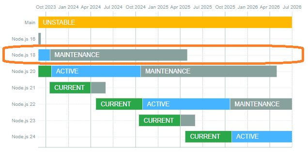
Node-RED provides a browser-based flow editor. This provides an easy way to see visually and modify your program flow. Flows can then be deployed to the runtime in a single click. Node-RED is built on Node.js. This lightweight runtime can be deployed on low-cost hardware (Raspberry Pi ) or cloud services (Microsoft Azure). This can bring data collection, analysis, and storage closer to the device. Real-time edge computing can then be achieved without latency issues. Since Node-RED requires Node.js to operate, we need to know the supported version of Node.js to install or update.
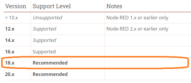
These are the current versions of Node.js that Node-RED supports. We will be using version 18 because it is recommended. This will be a stable environment for our programs.
Node.js Releases
The current version installed on your computer can be seen by entering the following command at the Windows command prompt.
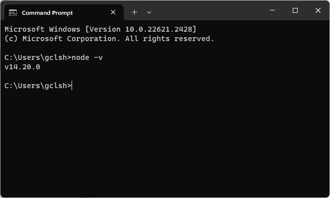
node -v
We will be installing version 18 of Node.js.
Currently, this version is in Maintenance mode — download version 18.18.2 from the following URL.
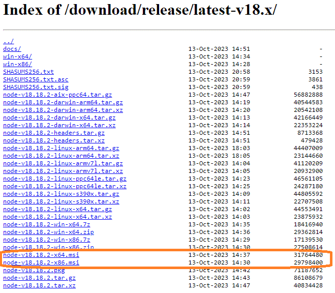
Since we have a 64-bit Windows 11 machine, select node-v18.18.2-x64.msi for the installation download file. Install the Node.js software.
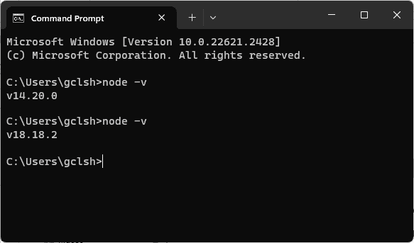
You can now see that we now have the version of node.js that we need.
Install Node-RED – Installing with npm
To install Node-RED, you can use the npm command that comes with node.js:
Open a command prompt in Windows and type the following command.
npm install -g –unsafe-perm node-red
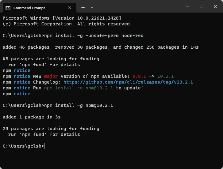
We have now installed Node-RED on our computer. At the command prompt, type node-red to start running the program.
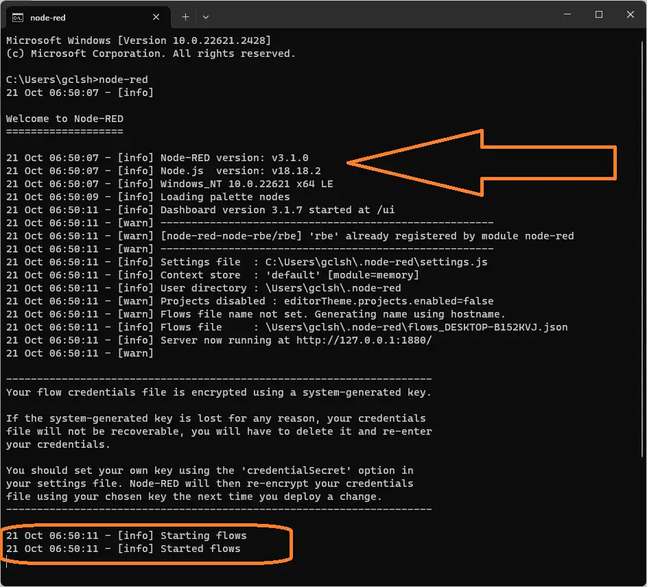
You can see the version number of Node-RED and the Node.js. Node-RED has been running since the flows started. The editor is browser-based. Open your browser and type http://localhost:1880/
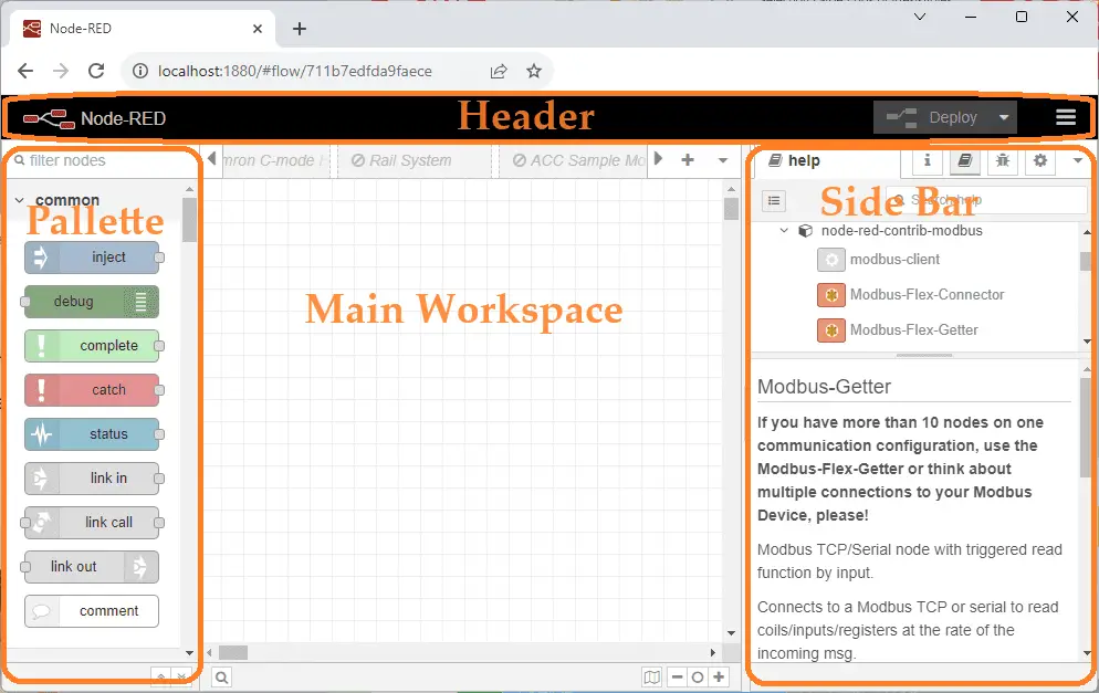
The editor has four main parts: Header, Palette, Main Workspace, and Side Bar.
We have an entire series on Node-RED to help get you started with this exciting IoT flow programming software.
Node-RED Modbus Nodes
Installing node-red-contrib-Modbus Palette
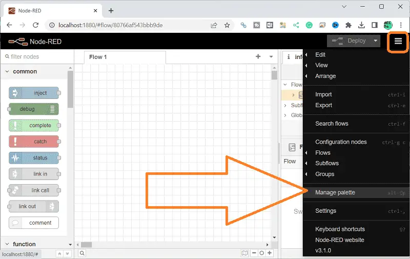
On the right-hand side of the header, select the three lines (pancake) to bring up the menu. Select manage palette.
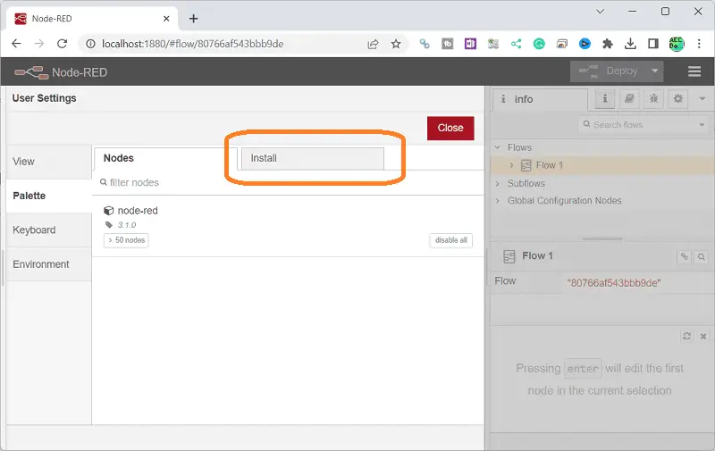
Under the user settings menu, select the palette on the left-hand side. This will show you the current nodes that you have installed. We currently have only the default nodes installed. Select the install tab.
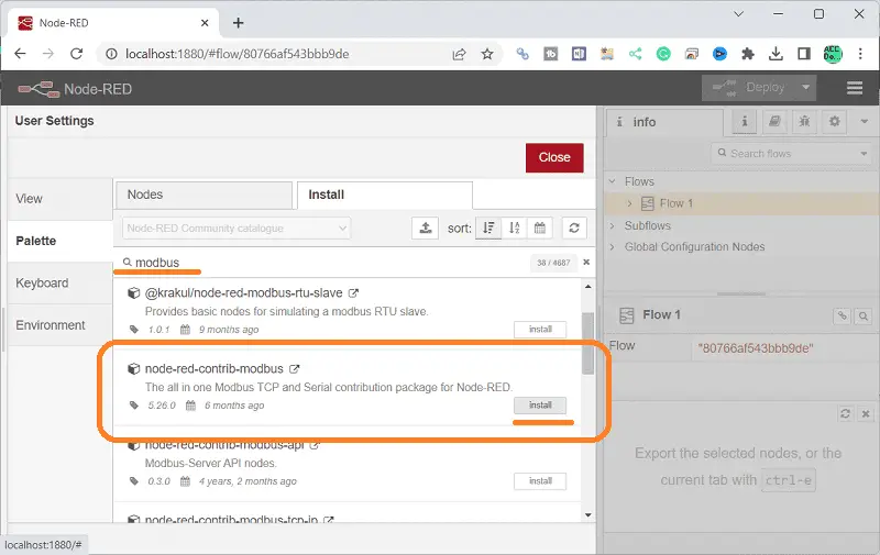
Type in ‘Modbus’ in the search field and press enter. Select the install button on the node-red-contrib-modbus palette.
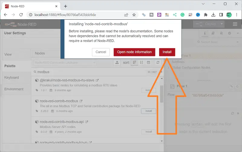
On the pop-up window, select Install.
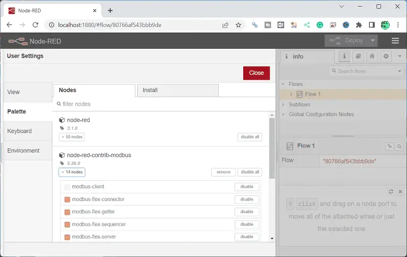
Node-red-contrib-modbus is now installed on your palette. Select the nodes tab. You can now see the 14 nodes installed under node-red-contrib-modbus. This menu can be used to install and delete node palettes. Select close.
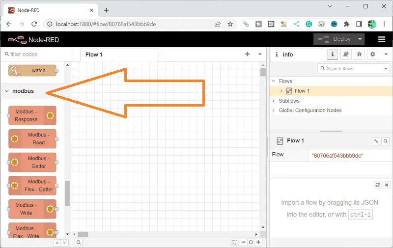
The palette on the editor will now contain the nodes we will need for Modbus communication. We can now gather and set the information required from the XY-MD02 temperature and humidity sensor and Productivity 2000 (P2000) PLC needed for Modbus communication.
XY-MD02 Temperature and Humidity Sensor
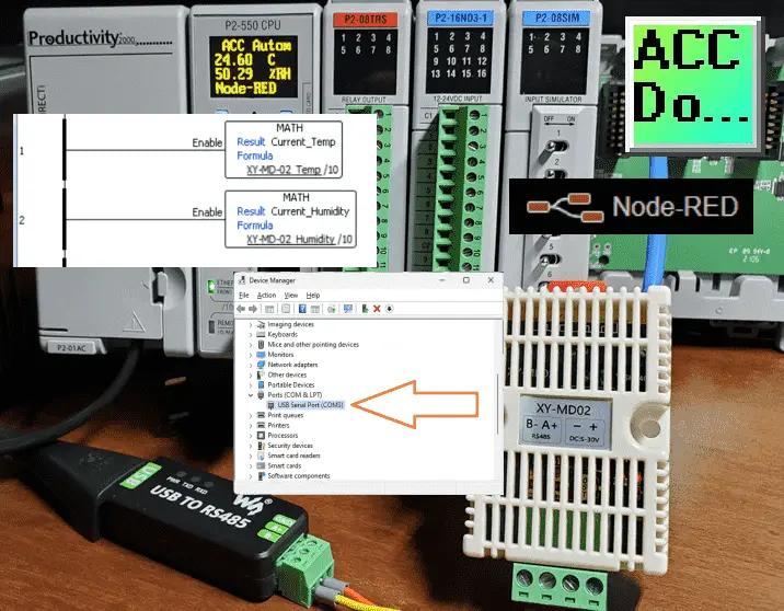
Using the Waveshare USB to RS485 converter, we will connect to our Windows 11 computer. Installation instructions are covered in the following post. This driver will assign the device a communication port (COM Port).
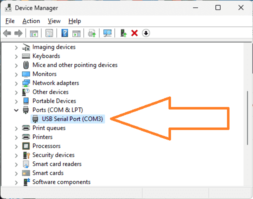
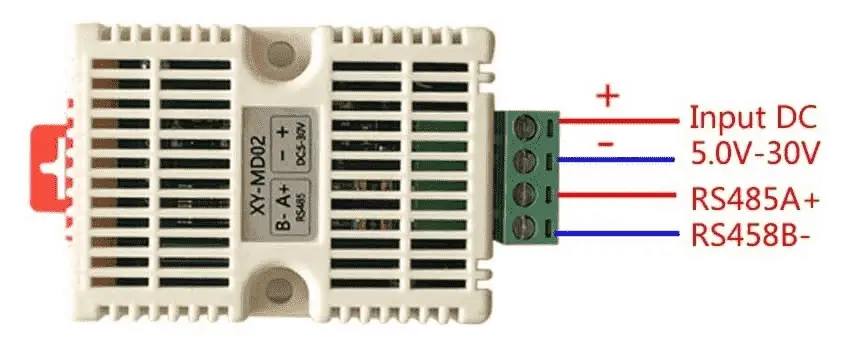
Using the device manager in Windows, you can see the communication port assigned to the USB to RS485 converter. Here is the wiring diagram for this sensor.
Using Simply Modbus, we can test the communication to the XY-MD02 Sensor. Simply Modbus Software has extended a 10% discount to ACC Automation readers. Use the following URLs to receive a discount on these software packages:
RTU/ASCII Master referral $54
RTU/ASCII Slave referral $54
TCP Client referral $54
Please send me an email to request further discounts on multiple package orders. Our sensor has Modbus RTU parameters: COM3, 9600, 8, 1, N. The Modbus address on this serial network is 1. (Default)
P2000 Modbus Server Program
Calling the Productivity Suite Programming software, we can set up our P2000 PLC to accept the Modbus values read from our XY-MD02 sensor.
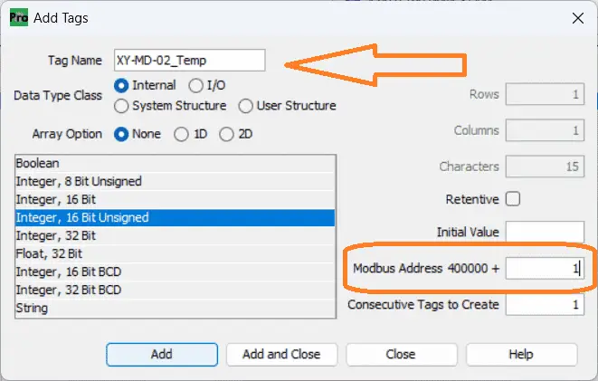
Display the tag database and add two more tags to store the temperature and humidity readings from the sensor.
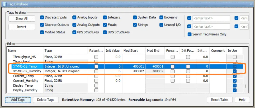
The Modbus address will be 400001 and 400002 for the temperature and humidity, respectively.
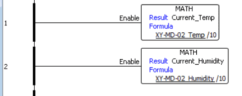
Temperature and humidity sensor values will have a decimal place understood. The MATH instruction converts the sensor reading into a real number so it can be displayed on our P2000 CPU.
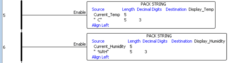
Pack String is used to create a string for the temperature and humidity sensor that shows the unit of measure.
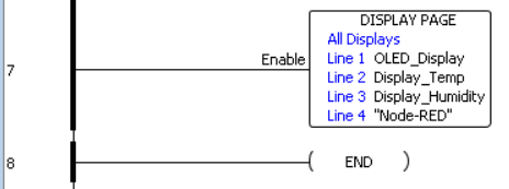
The Display Page instruction is modified to show the OLED display’s temperature and humidity on lines 2 and 3. We now have our program and Modbus addresses set for our system. Call up the Ethernet ports from the CPU module. This can be done by selecting the following from the main menu: Setup | Hardware Config.
Double-click on the P2-550 CPU unit and select the Ethernet port.
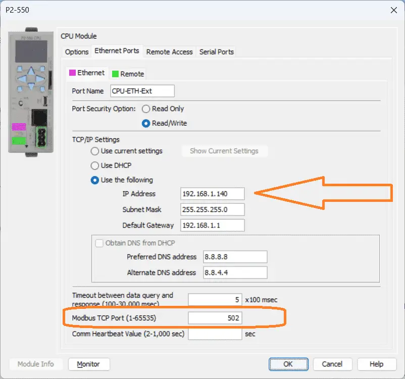
A static IP address has been entered for the P2000 CPU. This is important to ensure that the address remains the same so our Node-RED program can find this controller. The Modbus TCP Port is set for the default of 502.
Download and ensure that the P2000 is in run mode. Our Productivity PLC is now set up for our Node-RED Modbus TCP communication. We can now look at creating our Node-RED flow program.
Node-RED Flow Program
Our Node-RED flow program will read the temperature and humidity values from our XY-MD02 sensor using Modbus RTU. It will then take these values and write them to the Productivity 2000 PLC using Modbus TCP (Ethernet).
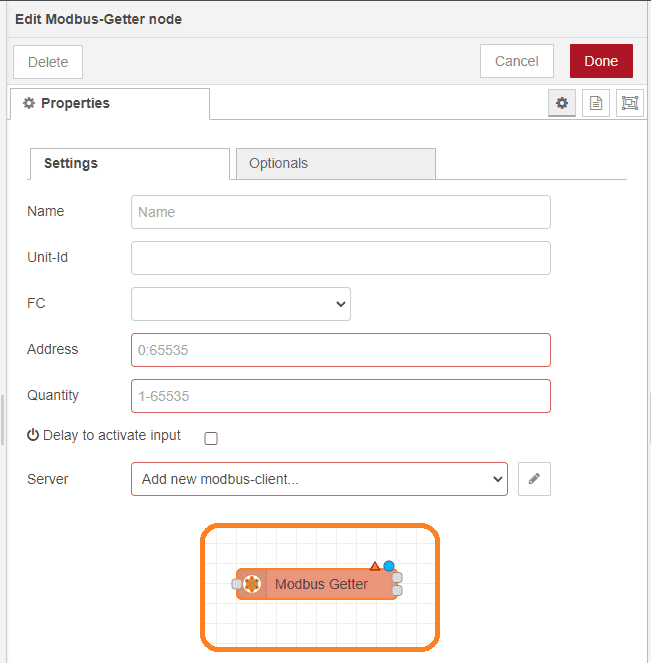
First, we will configure a Modbus RTU node (Modbus-Getter) to read the temperature and humidity values from the XY-MD02 sensor. When you first drag the Modbus Getter node onto the workspace, you will see a red triangle. This indicates that you need to set up the parameters.
In settings under properties, you can click the edit icon for the server to add or modify a Modbus client.
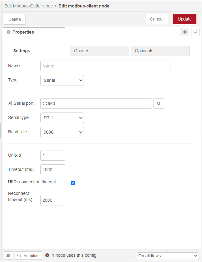
From the parameters above, we can enter the data for the Modbus RTU communication to the XY-MD02 Temperature and Humidity sensor.
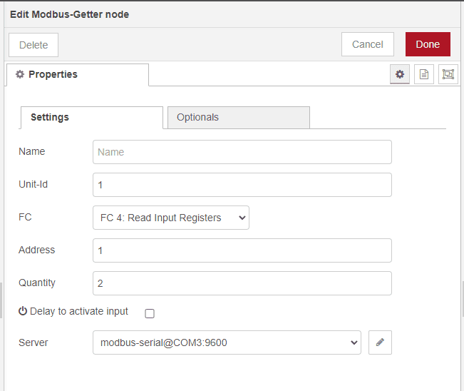
In settings under properties again, we can address the unit number, address, and number of registers to return.
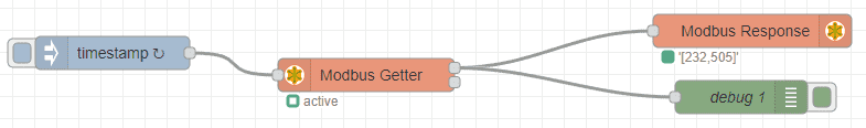
We can quickly test our flow program for our sensor by adding an Injection, Modbus Response, and debug nodes.
Note: Our injection node will be set up for a delay of 5 seconds to ensure initialization of the ports and then update every 0.5 seconds when running.
A Modbus Flex Write node will be used to write the information from the XY-MD02 into the Productivity 2000 PLC.
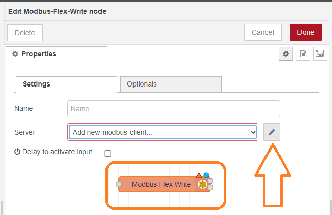
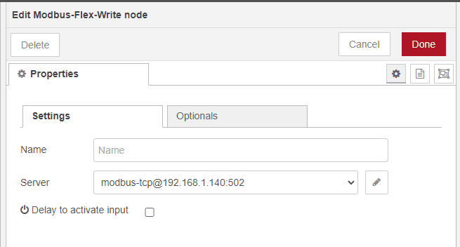
Once again, we can set up the parameters for this node.
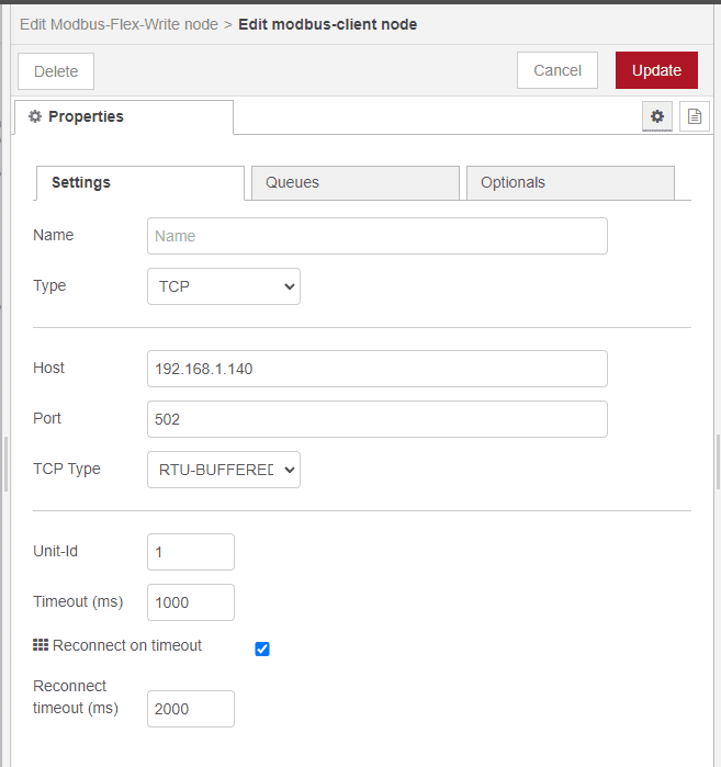
Use the P2000 PLC Ethernet Modbus Server information to set up the Node-RED Modbus Client Node.
Modbus Flex Write will use a function node to process the sensor values and prepare them for writing to the PLC.
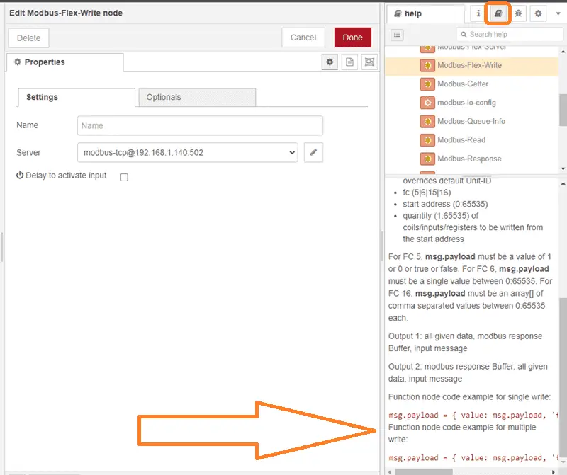
Looking at the help file for the Modbus-Flex-Write, you will see the code that we can modify for our function node. The function node can perform any necessary calculations or conversions on the sensor values in the function node. For example, we may need to convert the temperature from Celsius to Fahrenheit or format the humidity value as a percentage. Once the values are processed, we can pass them to a Modbus TCP node.
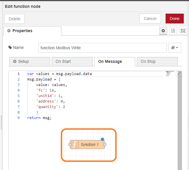
The actual code that you see is javascript. We store the previous Modbus Getter sensor values in a variable called values. Creating the message payload for the Modbus Flex Write will consist of the values for the temperature and humidity. It also includes the Modbus function code, unit ID, address, and quantity.
The function / Modbus Flex Write node is now configured to write the temperature and humidity values to the Productivity 2000 PLC.
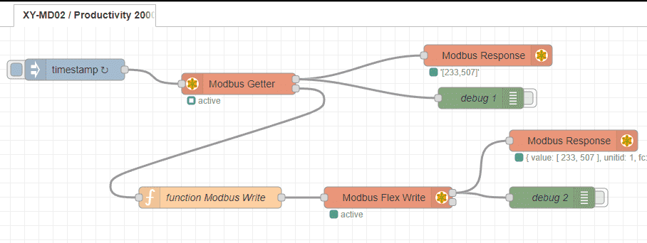
We can add a Modbus Response and debug nodes to our flow for troubleshooting.
With our Node-RED flow program complete, we can deploy it and start monitoring the temperature and humidity values from our XY-MD02 sensor on the Productivity 2000 PLC. This integration between Node-RED and the PLC allows for seamless data exchange and enhances the overall functionality of our system.
Download the PLC and flow programs here.
Watch the video below to see the running and configuration of the Node-RED Flow communication program from the XY-MD02 sensor to the Productivity 2000 Series PLC.
Productivity 2000 Series PLC from Automation Direct
Overview Link (Additional Information on the Unit)
Configuration (Configure and purchase a system – BOM)
User Manual and Inserts (Installation and Setup Guides)
Productivity Suite Overview (Features of the fully functional free software package for the Productivity Family of PLC (PAC) controllers)
Productivity Suite Programming Software (Free Download Link)
This software contains all the instructions and help files for the Productivity Series.
Watch on YouTube: Productivity 2000 PLC Node-RED Modbus TCP
If you have any questions or need further information, please contact me.
Thank you,
Garry
If you’re like most of my readers, you’re committed to learning about technology. Numbering systems used in PLCs are not challenging to learn and understand. We will walk through the numbering systems used in PLCs. This includes Bits, decimals, Hexadecimal, ASCII, and Floating points.
To get this free article, subscribe to my free email newsletter.
Use the information to inform other people how numbering systems work. Sign up now.

The ‘Robust Data Logging for Free’ eBook is also available for free download. The link is included when you subscribe to ACC Automation.