A PLC batch process system is a type of process control system that uses programmable logic controllers (PLCs) to control and automate a specific set of batch processing tasks. PLCs are industrial computers designed to monitor sensors, control actuators, and perform logic-based decisions based on pre-programmed instructions. In a batch process system, PLCs can be used to control the flow of materials, manage the timing of operations, and monitor the progress of batches. This can help improve the efficiency, accuracy, and consistency of batch-processing processes in chemical manufacturing, food processing, and pharmaceuticals.
The five steps for PLC program development will be followed to ensure a successful implementation of our batch system. EasyPLC machine simulator will be used to follow a recipe. This recipe will include six ingredients, mixing, and temperature. The Do-More designer PLC simulator will communicate Modbus TCP to EasyPLC. We will develop the code to measure and combine the ingredients into a hopper. The hopper will then be transferred to a mixer. Once the batch is in the mixer, the product will be heated and mixed for the time and temperature specified in the recipe. Let’s get started programming our batch system.
Learn PLC programming the easy way. See below for a 10% discount on this cost-effective learning tool. Invest in yourself today.
Previously we have done the following:
Easy PLC Installing the Software – Video
EasyPLC Software Suite – Quick Start – Video
Click PLC – Easy Transfer Line Programming – Video
Productivity PLC Simulator – Chain Conveyor MS – Video
Do-More PLC – EasyPLC Box Selection Program – Video
Click PLC EasyPLC Gantry Simulator – Video
Click PLC Simple Conveyor EasyPLC – Video
EasyPLC Paint Line Bit Shift – BRX Do-More PLC – Video
Click PLC – EasyPLC PLC Mixer Programming – Video
Click PLC EasyPLC Warehouse Stacker Example – Video
– Operation Video
EasyPLC Machine Simulator Productivity PLC Robotic Cell – Video
EasyPLC Simulator Robotic Cell Click PLC – Video
EasyPLC Simulator Robotic Cell BRX Do-More PLC – Video
– EasyPLC Factory Editor Robotic Cell Additions Video
4 Way Traffic Light PLC Program EasyPLC – Video
Rock Crusher Plant EasyPLC BRX Do-More – Video
Freight Carrier Weighing and Distribution EasyPLC – Video
EasyPLC Machining Center Loading Robots – Video
EasyPLC Palletizing Robot Programming Click PLC – Video
EasyPLC Machine Editor – Design a Simulation – Video
PLC Programming Mixing Tank – EasyPLC / Do-More – Video
EasyPLC Solder Robot PLC Programming – Video
PLC Programming – A Tutorial for Beginners – Video
Automated Parking Demo Video
Parking Cars Simulator PLC Programming Part 1 – Video
Parking Cars Simulator PLC Programming Part 2 – Video
PLC Programming with Pneumatic Synchronization – Video
The Ultimate Guide to PLC Programming for Sorting Operations – Video
Define the task: (Step 1 – Batch Processing with PLC Systems)
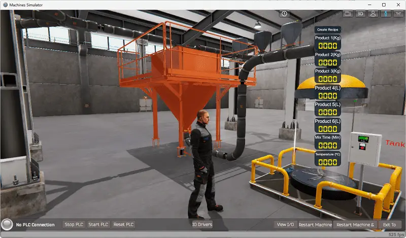
The first step of PLC program development is to define the task to determine what must be done. EasyPLC software suite contains this batch process example in the machine simulator. This is just one of many machines with the software so you can learn and develop your PLC programming skills.
Start the EasyPLC Machine Simulator (MS). Select the start button on the main page or select machines from the main menu at the top of the machine’s simulator window.
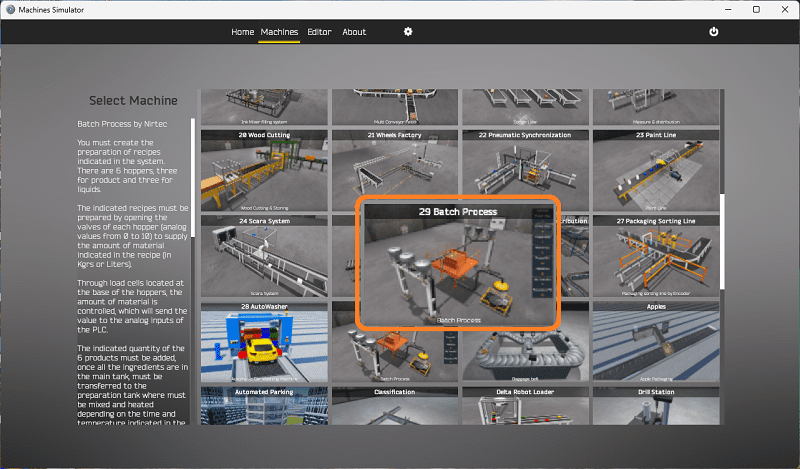
All the available machines will now be displayed. Click on the “29 Batch Process.”
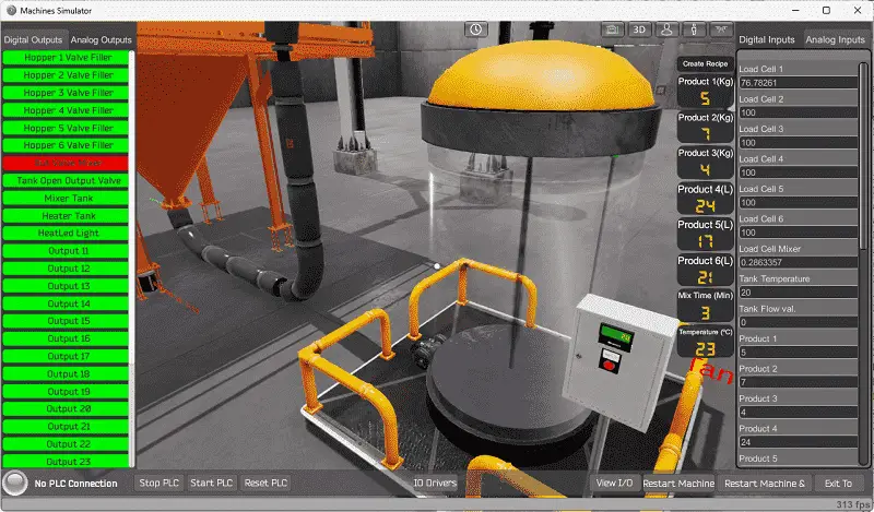
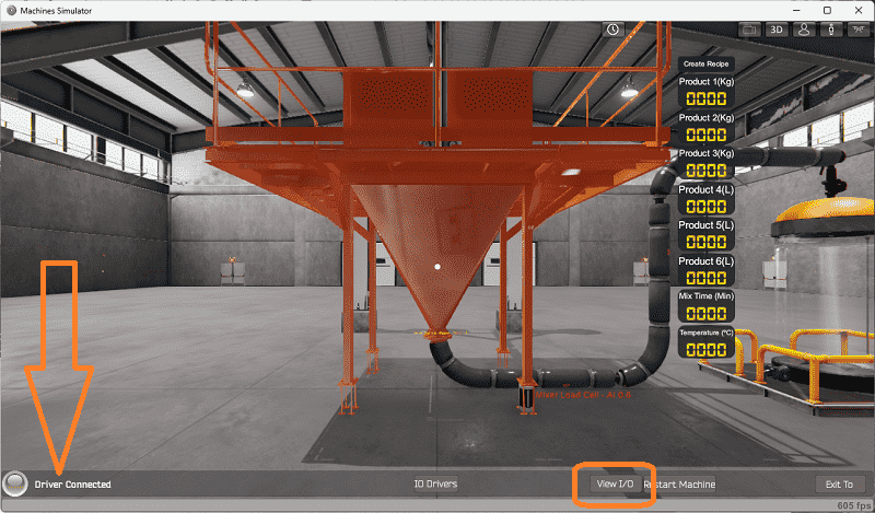
This is the example that we will be programming. To the left of the screen, information will be displayed on how this process needs to function.
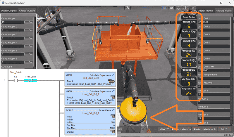
You must create the preparation of recipes indicated in the system. There are six hoppers, three for products and three for liquids. The indicated recipes must be prepared by opening the valves of each hopper (analog values from 0 to 10) to supply the amount of material shown in the formula (in Kgs or Liters). The amount of material is controlled through load cells located at the base of the hoppers, which will send the value to the analog inputs of the PLC. The indicated quantity of the six products must be added once all the ingredients are in the main tank and transferred to the preparation tank. It must be mixed and heated depending on the time and temperature indicated in the recipe. The recipe is revealed to the PLC by pressing the Create Recipe button on the screen, which sends the values of quantities, time, and temperature through the analog inputs.
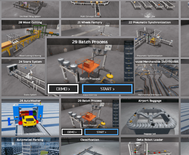
The machine simulator batch process does not have a demo mode. Start the “29 Batch Process” in start mode.

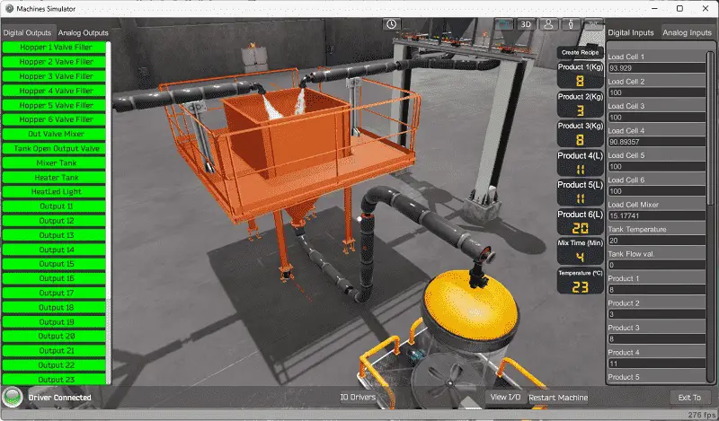
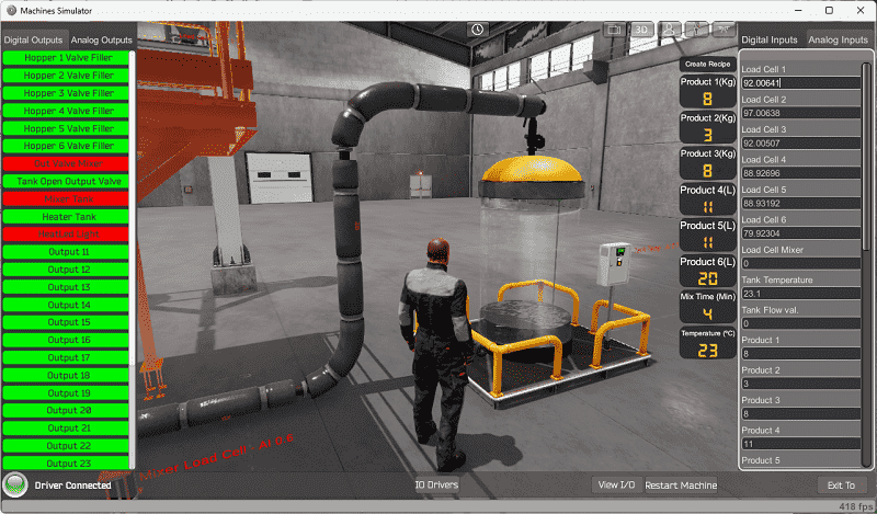
Move around the 3D virtual environment. The icons on the top of the window will allow you to move around this 3D environment.
The first icon is the default selection. This will enable you to move around without bumping into the components. The first-person mode will mimic a person in your 3D learning world. The third person is used to show the operator’s relationship to the machine. The last icon will automatically show you around this virtual environment. Once we understand what must be done, we can move on to the next step in our PLC program development.
Define the Inputs and Outputs: (Step 2 – Batch Processing with PLC Systems)
The View IO at the bottom of the machine simulator window will display the inputs and outputs required for this batch processing system example. Select the View IO at the bottom of the machine simulator window.
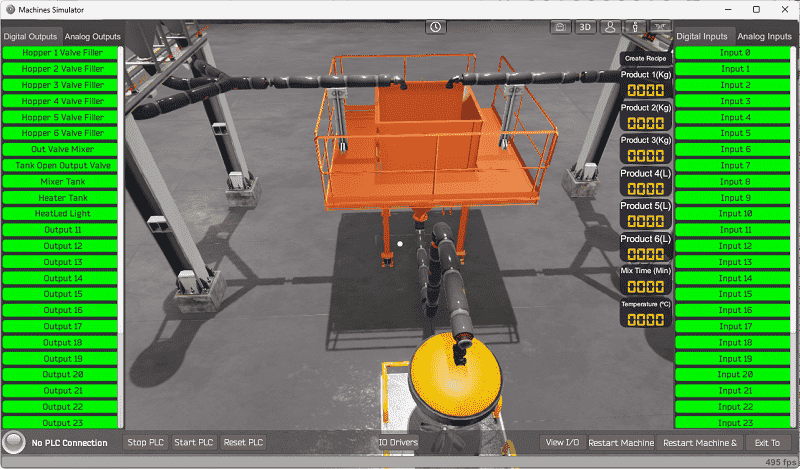
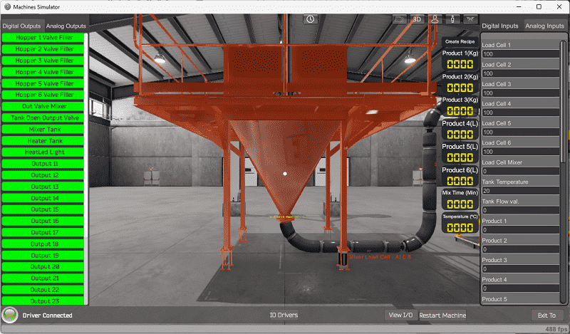
The EasyPLC batch processing system example will require 11 digital outputs. No digital inputs are needed. Select the Analog outputs and inputs.
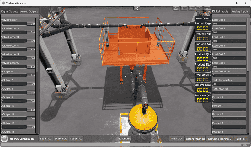
Six analog outputs are required to control the hoppers. Seventeen analog inputs are required. These are for the hopper values, recipe values, temperature, and flow rates.
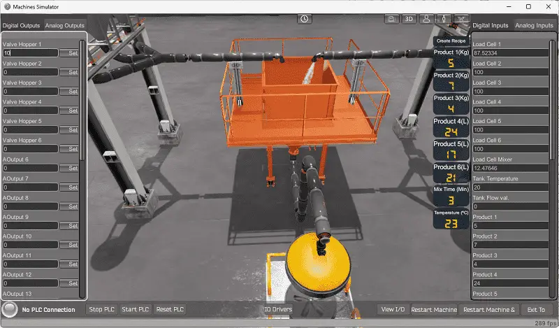
The EasyPLC start mode will allow you to control this batch process manually.
This is ideal if you need clarification on what output or input is doing.
The started machine simulator window will allow you to manually run the machine simulator without any control or PLC connection.
Select the packaging line sorting digital or analog outputs on the left side of the screen by clicking on them with the mouse or changing the value for the Analog. The right side will show you the corresponding digital inputs or analog values.
The restart button on the bottom of the machine simulator window will reset the scene back to the start.
Move around the 3D environment and ensure you know what each input and output represent.
The following table will define the inputs and outputs (IO) and Modbus addresses in the Do-More Designer Simulator PLC we will use for this program.
| Digital Type | Description | Do-More PLC Modbus Address | Machine Simulator Modbus Address |
| PLC Output – MS Input | Hopper 1 Valve (Filling) | MI1 – 10001 | 0 |
| PLC Output – MS Input | Hopper 2 Valve (Filling) | MI2 – 10002 | 1 |
| PLC Output – MS Input | Hopper 3 Valve (Filling) | MI3 – 10003 | 2 |
| PLC Output – MS Input | Hopper 4 Valve (Filling) | MI4 – 10004 | 3 |
| PLC Output – MS Input | Hopper 5 Valve (Filling) | MI5 – 10005 | 4 |
| PLC Output – MS Input | Hopper 6 Valve (Filling) | MI6 – 10006 | 5 |
| PLC Output – MS Input | Output Valve to Mixer | MI7 – 10007 | 6 |
| PLC Output – MS Input | Tank Open Valve | MI8 – 10008 | 7 |
| PLC Output – MS Input | Mixer Tank – Mix | MI9 – 10009 | 8 |
| PLC Output – MS Input | Mixer Heater Tank | MI10- 10010 | 9 |
| PLC Output – MS Input | Heat LED Light (In process) | MI11- 10011 | 10 |
| PLC Analog Output – MS Analog Input | Valve Hopper 1 | MHR1 – 1 | 0 |
| PLC Analog Output – MS Analog Input | Valve Hopper 2 | MHR2 – 2 | 1 |
| PLC Analog Output – MS Analog Input | Valve Hopper 3 | MHR3 – 3 | 2 |
| PLC Analog Output – MS Analog Input | Valve Hopper 4 | MHR4 – 4 | 3 |
| PLC Analog Output – MS Analog Input | Valve Hopper 5 | MHR5 – 5 | 4 |
| PLC Analog Output – MS Analog Input | Valve Hopper 6 | MHR6 – 6 | 5 |
| PLC Analog Input – MS Analog Output | Load Cell 1 | MHR101 – 101 | 100 |
| PLC Analog Input – MS Analog Output | Load Cell 2 | MHR102 – 102 | 101 |
| PLC Analog Input – MS Analog Output | Load Cell 3 | MHR103 – 103 | 102 |
| PLC Analog Input – MS Analog Output | Load Cell 4 | MHR104 – 104 | 103 |
| PLC Analog Input – MS Analog Output | Load Cell 5 | MHR105 – 105 | 104 |
| PLC Analog Input – MS Analog Output | Load Cell 6 | MHR106 – 106 | 105 |
| PLC Analog Input – MS Analog Output | Load Cell Mixer | MHR107 – 107 | 106 |
| PLC Analog Input – MS Analog Output | Tank Temperature | MHR108 – 108 | 107 |
| PLC Analog Input – MS Analog Output | Tank Flow Valve | MHR109 – 109 | 108 |
| PLC Analog Input – MS Analog Output | Product 1 (Recipe) | MHR110 – 110 | 109 |
| PLC Analog Input – MS Analog Output | Product 2 (Recipe) | MHR111 – 111 | 110 |
| PLC Analog Input – MS Analog Output | Product 3 (Recipe) | MHR112 – 112 | 111 |
| PLC Analog Input – MS Analog Output | Product 4 (Recipe) | MHR113 – 113 | 112 |
| PLC Analog Input – MS Analog Output | Product 5 (Recipe) | MHR114 – 114 | 113 |
| PLC Analog Input – MS Analog Output | Product 6 (Recipe) | MHR115 – 115 | 114 |
| PLC Analog Input – MS Analog Output | Mix Time Min (Recipe) | MHR116 – 116 | 115 |
| PLC Analog Input – MS Analog Output | Temperature (Recipe) | MHR117 – 117 | 116 |
Note: The machine simulator will be offset by one for the Modbus Addresses. See the video below to determine the inputs and outputs.
Develop a logical sequence of operation: (Step 3 – Batch Processing with PLC Systems)
A PLC programmer must know everything about the sequence and operation of the machine before programming. The sorting operation simulator is an excellent way to learn to program. Flow charts or sequence tables can be used to understand the process that needs to be controlled thoroughly. It must also answer questions like the following:
What happens when electrical power or pneumatic air is lost? What happens when the input/output devices fail? Do we need redundancy?
This step is where you will spend most of your time. Understanding everything about the operation will save you time. It will help prevent you from continuously re-writing the PLC program logic. Knowing all these answers to how the system reacts is vital in developing the PLC program. This does not have to be a formal document. You must have a method to account for every condition in the machine being programmed.
Our batch process does not have a start-stop control panel. If the created recipe differs from the current one, the batch process system will start.

The current load cell values minus the recipe value will be the set value of the load cells. Load cells 1 to 3 will sequence the ingredient into the main tank. Cells 4 to 6 will also sequence putting the ingredients into the main tank.
Once the product is in the main tank, it will be sent to the preparation tank. The mixer will then start for the mixing time specified in the recipe. The heater will heat the mixture to the temperature in the recipe.
The preparation tank will empty when the mixing time and temperature have been reached. The tank flow will indicate when the tank is empty. This will then reset the batch process and wait for the following recipe to create.
If the load cells fall below 50% of their value, they will be topped up at the end of the batch process cycle before the next recipe is made.
A PLC programmer must know how everything about the sequence and operation of the machine before programming.
Ensuring you know what must happen will help clarify what is required in the PLC program. Ask questions or view existing documentation to ensure you understand the logical steps to the machine’s operation. This may involve speaking with the manufacturer, operators, engineers, etc.
Develop the Do-More PLC program: (Step 4 – Batch Processing with PLC Systems)
Using the information from the previous steps, we can now program our Do-More PLC Simulator. The BRX Do-More PLC Series will take you through installing the program, communicating with the controller, providing instructions, and addressing the controller.
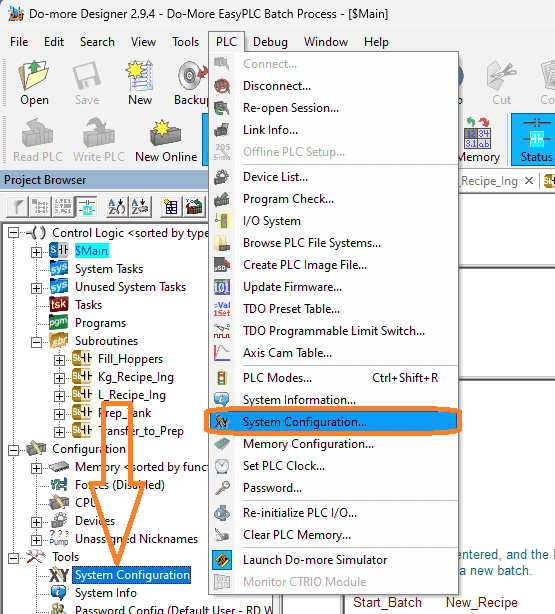
Select the system configuration under PLC on the main menu. You can also call this up by selecting system configuration under the tools menu in the project browser window.
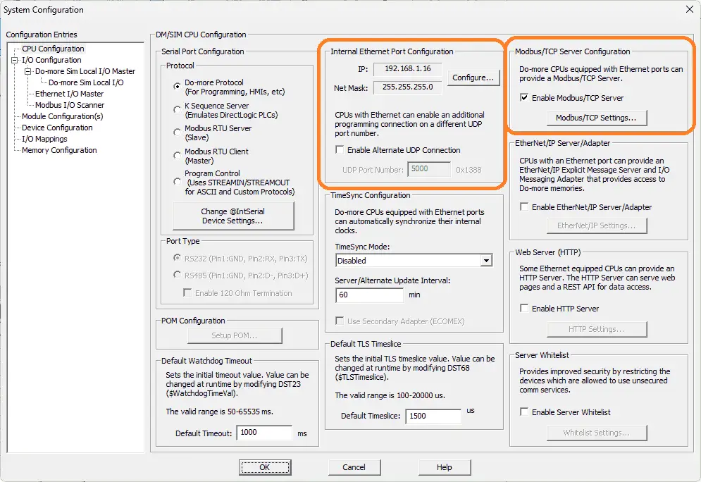
The computer’s IP address can be seen under the “Internal Ethernet Port Configuration.”
Modbus TCP Server is selected by default; however, we can also ensure this is the case in the system configuration window.
Our PLC is now a Modbus TCP Server to the EasyPLC Modbus TCP Client. Please make a note of the static IP address that we are using for the BRX Do-More PLC. This will be used later to connect to the EasyPLC machine simulator.
The ladder logic plc programming is split up to make it easier to read and program. We have subroutines for the KG and Litre ingredient control, transfer to preparation tank, preparation tank, and fill hoppers. These will control the batch process sequence. The main program will call these subroutines and the rest of the ladder logic program for the batch process system.
Main Ladder Logic Program
The first scan bit is used in our program to reset the system. This ensures that the batch process simulator and PLC start with the same values.
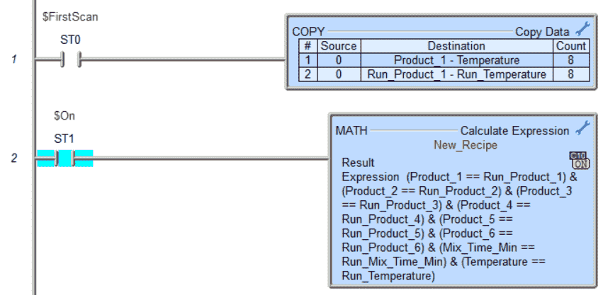
The math instruction compares the existing recipe with the required formula. If they are the same, then bit C10 will be turned on.
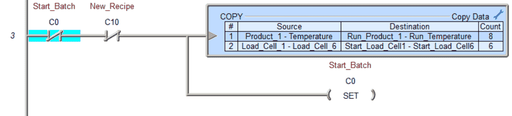
Start the batch process by setting the C0 bit. If the batch start has not begun and there is a new recipe, copy the recipe parameters to the internal memory area. Also, copy the start load cell values to an internal memory area.
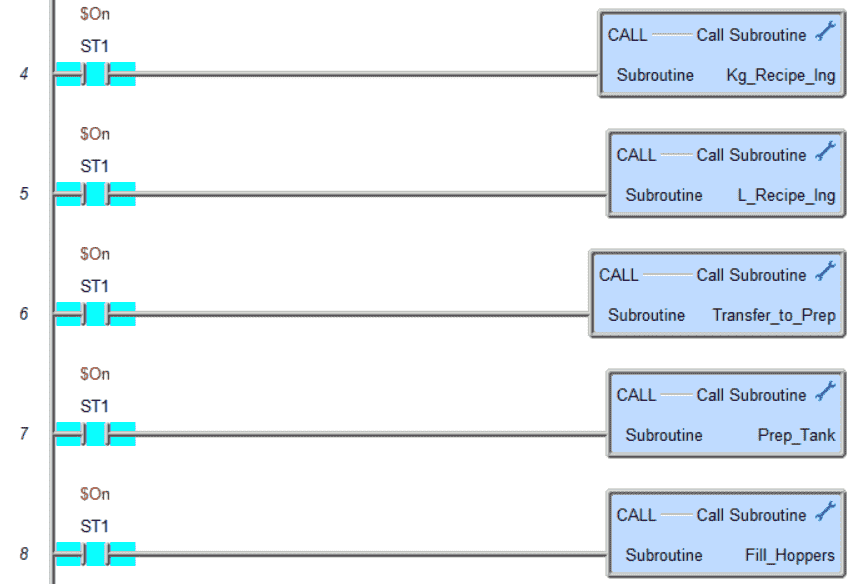
Call each of the different subroutines. You will notice that each subroutine is called every scan. This means that the PLC is constantly scanning these routines.
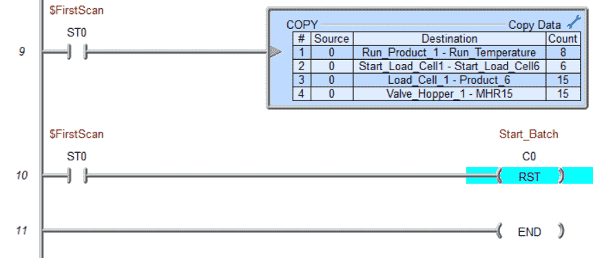
The first scan bit is used to zero out all the internal registers for the batch process system. It will also reset the start batch bit C0. This is the end of the main routine logic.
KG Recipe Ingredients Subroutine
When the start batch has begun, only one product at a time can be measured for load cells 1 to 3.
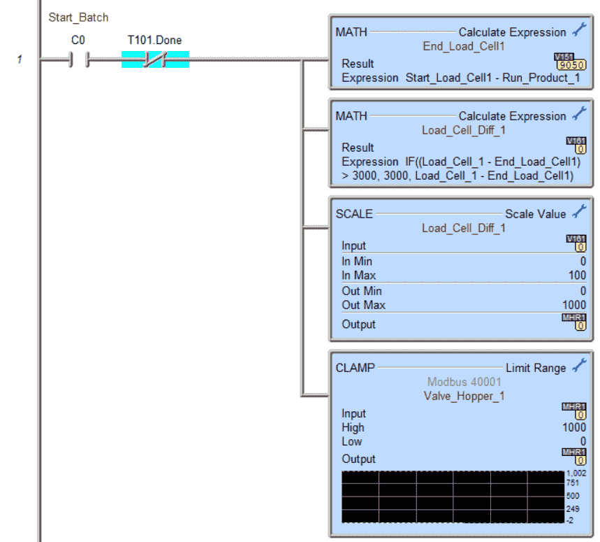
The end load cell one value is calculated using the math instruction. Another math instruction determines the difference between the current and ends load cell value. If this is greater than the absolute value of 3000, then the value of 3000 is put in the difference.
The scale value is used to scale the difference to the valve output. This control valve is for adding the ingredient. During the last 1.00 KG, the control valve is proportioned from 100% open to closed. (0%) The clamp instruction ensures the valve is between 0 (Closed) and 1000 (Fully Opened).
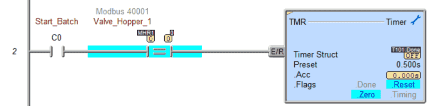
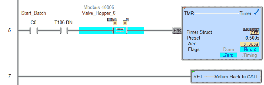
When the first ingredient valve is closed, a timer activates for ½ second. The first ingredient has now been added.
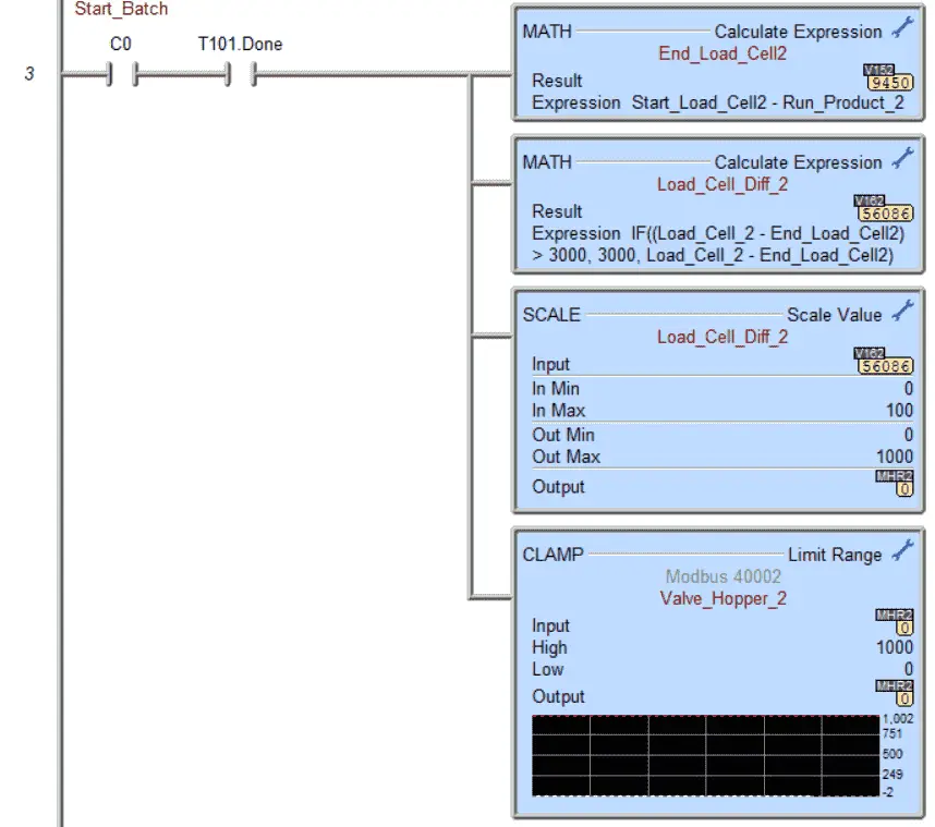
After the first ingredient is added, we add the second ingredient in the same manner as explained above.
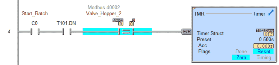
When the second ingredient valve is closed and the first ingredient timer is complete, the second ingredient timer will then time for ½ second.
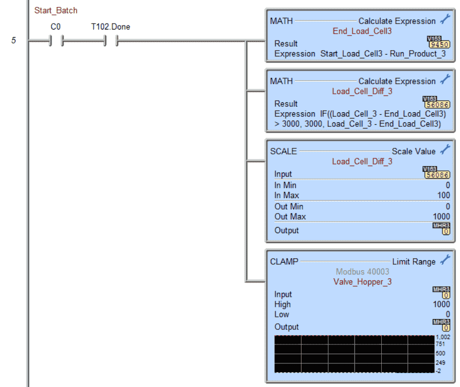
After the second ingredient is added, we add the third ingredient in the same manner as the other two.
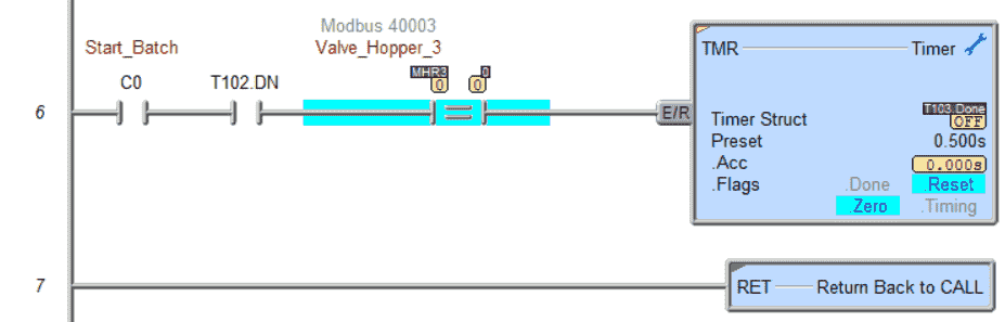
When the third ingredient valve is closed and the second ingredient timer is complete, the third ingredient timer will then time for ½ second.
Liters Recipe Ingredients Subroutine
When the start batch has begun, only one product at a time can be measured for load cells 4 to 6.
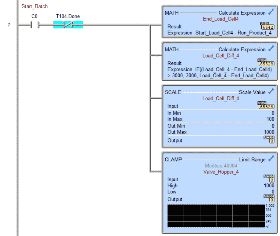
The end load cell four value is calculated using the math instruction. Another math instruction determines the difference between the current and load cell end value. If this is greater than the absolute value of 3000, then the value of 3000 is put in the difference.
The scale value is used to scale the difference to the valve output. This control valve is for adding the ingredient. During the last 1.00 L, the control valve is proportioned from 100% open down to close. (0%) The clamp instruction ensures the valve is between 0 (Closed) and 1000 (Fully Opened).
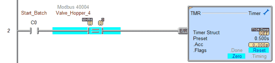
When the fourth ingredient valve is closed, a timer activates for ½ second. The fourth ingredient has now been added.

After the fourth ingredient is added, we add the fifth ingredient in the same manner as explained above.
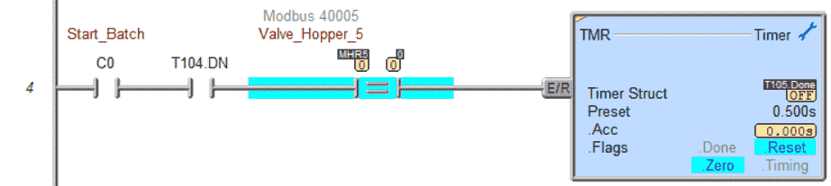
When the fifth ingredient valve is closed and the fourth ingredient timer is complete, the fifth ingredient timer will then time for ½ second.

After adding the fifth ingredient, we add the sixth ingredient, similar to the other two.
When the sixth ingredient valve is closed and the fifth ingredient timer is complete, the sixth ingredient timer will then time for ½ second.
Transfer to Preparation Tank Subroutine
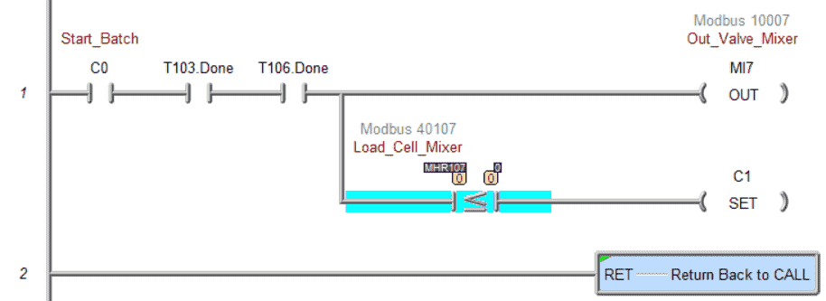
The valve mixer output will be on when the third and sixth timers are timed out. This indicates that all the ingredients have been put into the batch. Once the transfer is complete by having the load cell mixer read zero, C1 will be activated. This will then start the preparation tank operations.
Preparation Tank Subroutine
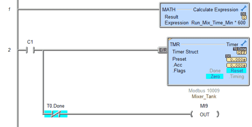
The first rung will multiply the run mixing time in minutes by 600. This will give us the run time in thousands of seconds.
The timer will then start timing based on this time calculated. Our mixer will be on in the tank if the timer is timing.
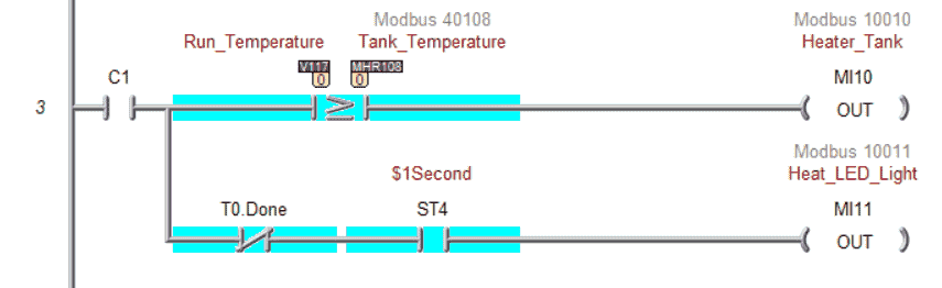
The tank heater will turn on if the tank temperature is below the recipe run temperature. This ensures that the batch is heated up to the set value in the recipe. If the recipe mix time is done, the heat LED light will be off, indicating that the batch process is complete.
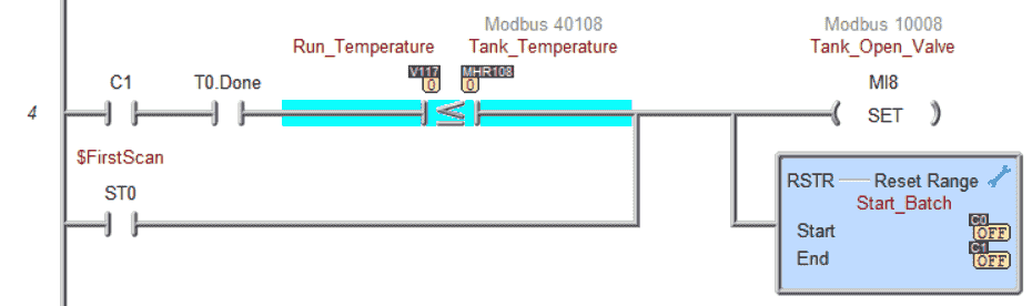
When the batch process mix time is complete, and the temperature is at the recipe set point, the tank open valve will be turned on. The batch is now complete.
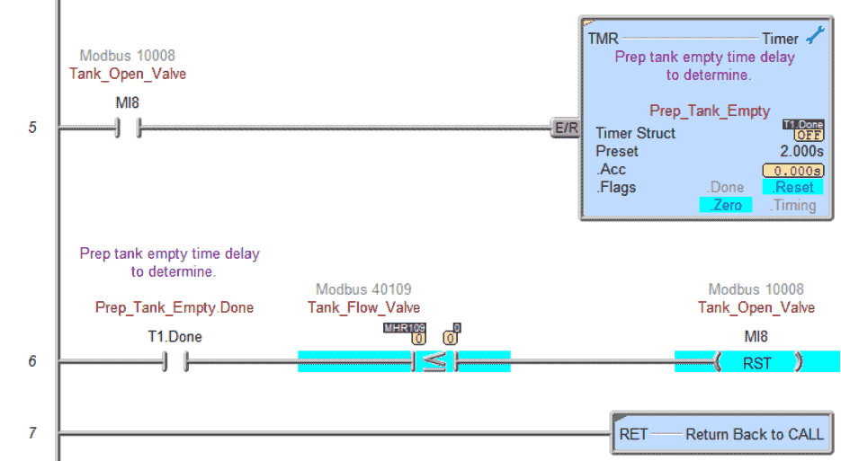
A two-second delay ensures that the emptying tank flow has started. When the timer has been completed, the flow is compared to 0. The tank open valve is turned off if it is equal to or less than.
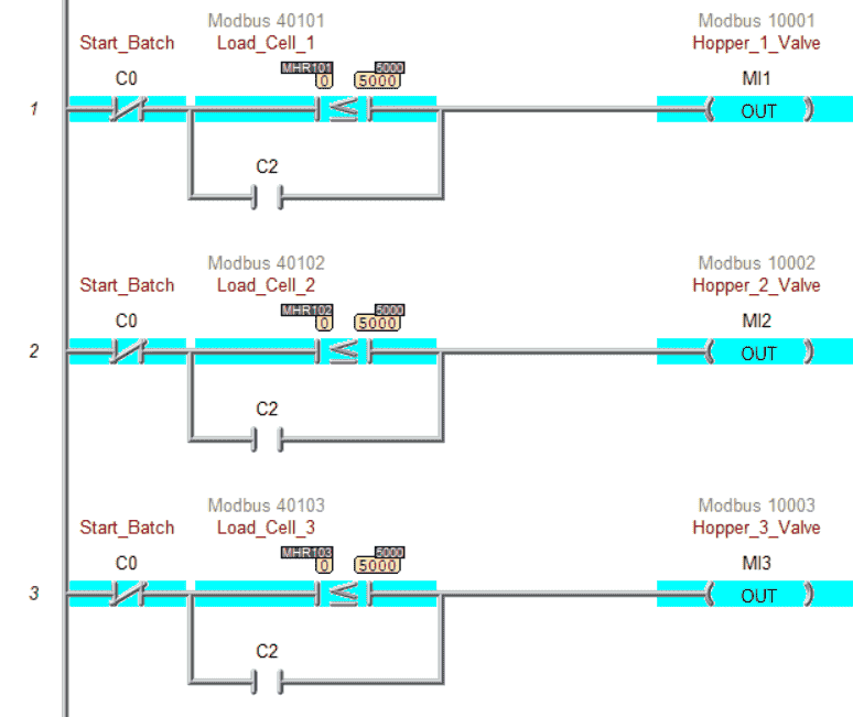
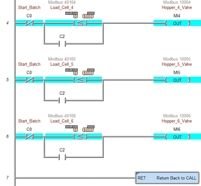
Fill Hoppers Subroutine
When the batch process is not running, and the ingredient hoppers are less than half full, they will automatically fill.
C2 is used to fill them manually.
Our ladder logic PLC program is complete. Download this to the Do-More Designer Simulator and ensure that the simulator is in run mode.
Watch the video below to see this Do-More PLC program in action.
Test the program: (Step 5 – Batch Processing with PLC Systems)
We will use Modbus TCP on our Do-More PLC simulator to communicate with the EasyPLC Machine Simulator.
Call up the “29 Batch Process” machine in start mode.
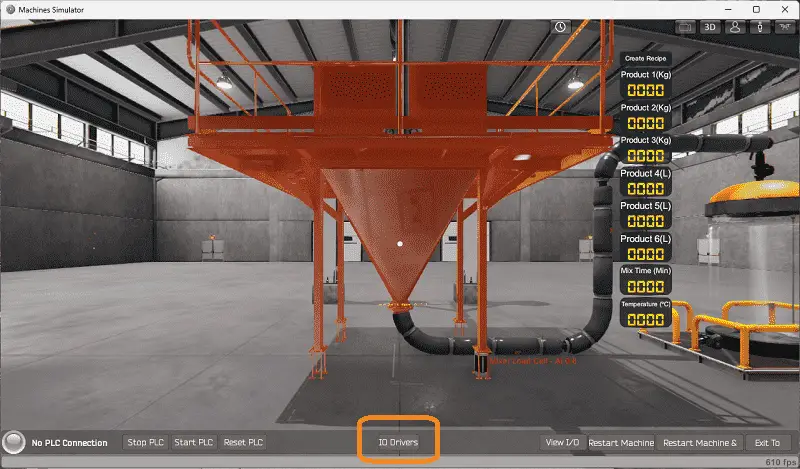
The status of the machine simulator will be at the bottom of the screen. Currently, we have no PLC connected. Select IO Drivers on the bottom middle of the screen.
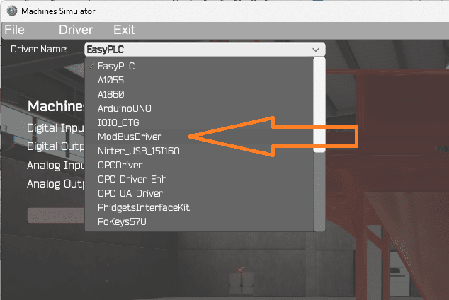
The EasyPLC driver is selected by default. Under the driver pull-down menu, select “ModBusDriver.” This driver will communicate Modbus TCP (Ethernet) and Modbus RTU (Serial). Select the down arrow on the driver’s name.
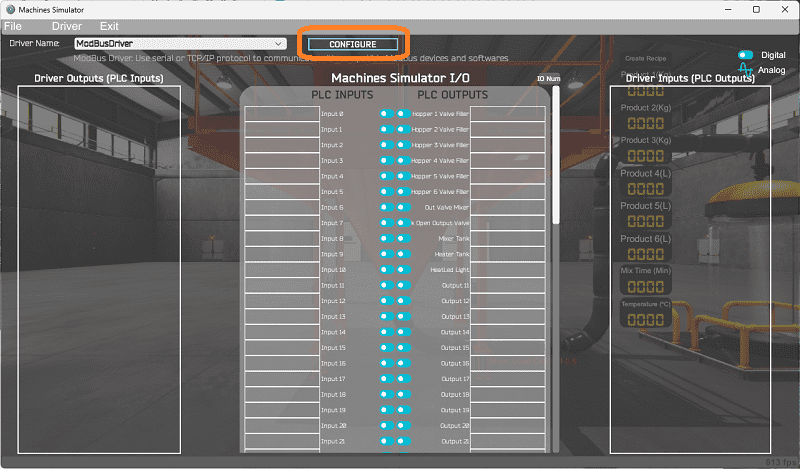
Select the configure button.
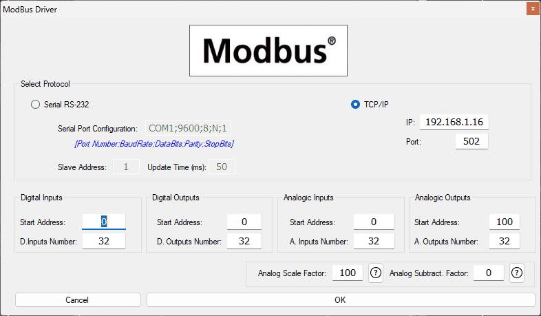
We can now enter the information for our Modbus driver. Select TCP/IP. This means the Ethernet port on the computer will communicate with the PLC.
The digital inputs from MS to the Do-More PLC will be MC1 to MC11. This will start at address 0 due to the offset of 1. We are indicating 32 digital inputs and outputs. This is fine because it is more than our EasyPLC machine simulator will require.
Analog inputs to MS from the Do-More PLC will be MHR1. Due to the offset of 1, the PLC analog will start at address 0. Analog outputs from MS to the Do-More PLC will start at MHR101.
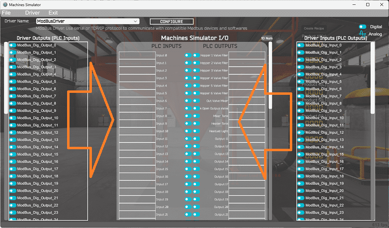
You will now see the inputs and outputs specified for the Modbus driver. We can manually assign the driver outputs to the PLC inputs and the driver inputs to the PLC outputs. However, the automatic assignment works well and will save you time.
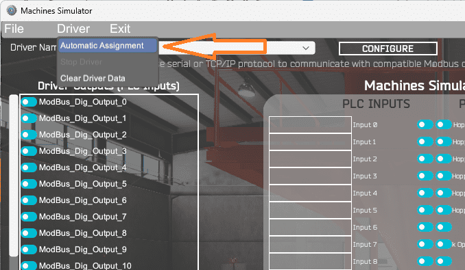
Select Automatic Assignment from the driver option in the main menu.
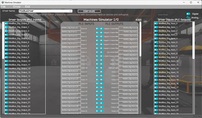
This will automatically assign the PLC IO to the Machine Simulator IO.
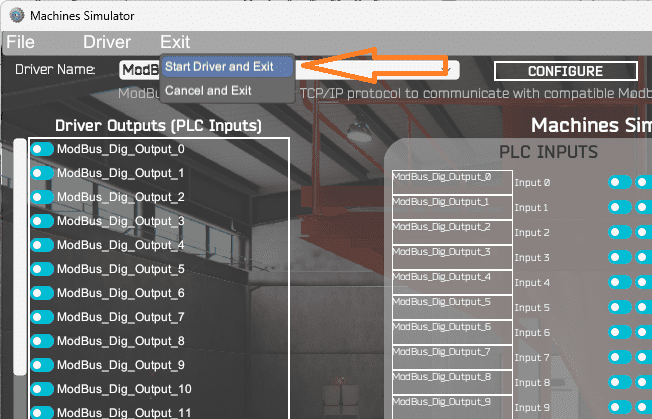
Select start driver and exit from the main menu.
On the bottom left side of the window, you will see that the driver communicates to the PLC with the green light. Select view IO to know the input and output status of the machine simulator.
Ensure that the PLC is in run mode. We can now operate our EasyPLC sorting operations machine.
Using the Data View window of the Do-More Designer programming software, we can also watch the inputs and outputs operate.
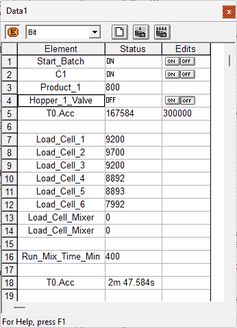
Watch the video below to see this operation.
If your program works correctly, it’s time to move on. If not, you’ll need to debug. This can be as simple as re-downloading and re-uploading your program or as complicated as re-designing your logic. You will notice that the program is written in stages. Each of the stages must be completed before moving to the next. This makes troubleshooting easy because you only look at one part of the code.
When using EasyPLC, debugging is quickly done without damaging any equipment. You may modify your logic several times before you get everything right! That’s okay—it’s all part of learning. After all: trial and error are often easier said than done! To learn more about developing logic, check out our tutorials on the five steps to PLC program development.
You can practice your modification and debug by modifying the batch process system in the following way:
– Add a start-stop on the control panel. This will allow the operator to have more control of the system.
– Add a separate top-up button on the control panel. The operator can push this button to fill the tanks before making the next recipe.
Let me know how you make out in the comments below.
Download the Do-More PLC sample program here.
Watch the video below to see the five steps of program development applied to the batch process machine. The machine simulator is one of the best applications to help you learn PLC programming.
EasyPLC Software Suite is a complete PLC, HMI, and Machine Simulator package. This PLC learning package includes the following:
Easy PLC – PLC Simulation allows programming in Ladder, Grafcet, Logic Blocks, or Script.
HMI System – Easily create a visual human-machine interface (HMI)
Machine Simulator – A virtual 3D world with real-time graphics and physical properties. PLC programs can be tested using EasyPLC or through other interfaces. (Modbus RTU, TCP, etc.)
Machine Simulator Lite – Designed to run on Android Devices.
Machine Simulator VR – Virtual Reality comes to life so you can test, train or practice your PLC programming.
Purchase your copy of this learning package for less than USD 75 for a single computer install or less than USD 100 to allow different computers.
Receive 10% off the price by typing in ACC in the comment section when you order. http://www.nirtec.com/index.php/purchase-price/
Learn PLC programming the easy way. Invest in yourself today.
Watch on YouTube: Streamline Your Operations: Optimizing Batch Processing with PLC Systems
If you have any questions or need further information, please get in touch with me.
Thank you,
Garry
If you’re like most of my readers, you’re committed to learning about technology. Numbering systems used in PLCs are not challenging to learn and understand. We will walk through the numbering systems used in PLCs. This includes Bits, decimals, Hexadecimal, ASCII, and Floating points.
To get this free article, subscribe to my free email newsletter.
Use the information to inform other people how numbering systems work. Sign up now.

The ‘Robust Data Logging for Free’ eBook is also available for free download. The link is included when you subscribe to ACC Automation.