These sorting operations will sort three bottles on separate conveyor lines creating an efficient and powerful machine. The PLC will use shift registers to track and control the position of the bottles. Two pick-and-place robots will be used to move the bottles, creating an ultimate machine to program. Sequencers will be used within the PLC programming to control the two-axis robots.
Now, let’s get started on this exciting project! The five steps for PLC program development will be followed to ensure successful implementation. This will guide you in creating these sorting operations. EasyPLC packaging sorting line will be connected to the Do-More designer PLC simulator using Modbus TCP (Ethernet). An operator panel with a start and stop, lighted pushbuttons, and an emergency stop will control the packaging sorting line.
Learn PLC programming the easy way. See below for a 10% discount on this cost-effective learning tool. Invest in yourself today.
Previously we have done the following:
Easy PLC Installing the Software – Video
EasyPLC Software Suite – Quick Start – Video
Click PLC – Easy Transfer Line Programming – Video
Productivity PLC Simulator – Chain Conveyor MS – Video
Do-More PLC – EasyPLC Box Selection Program – Video
Click PLC EasyPLC Gantry Simulator – Video
Click PLC Simple Conveyor EasyPLC – Video
EasyPLC Paint Line Bit Shift – BRX Do-More PLC – Video
Click PLC – EasyPLC PLC Mixer Programming – Video
Click PLC EasyPLC Warehouse Stacker Example – Video
– Operation Video
EasyPLC Machine Simulator Productivity PLC Robotic Cell – Video
EasyPLC Simulator Robotic Cell Click PLC – Video
EasyPLC Simulator Robotic Cell BRX Do-More PLC – Video
– EasyPLC Factory Editor Robotic Cell Additions Video
4 Way Traffic Light PLC Program EasyPLC – Video
Rock Crusher Plant EasyPLC BRX Do-More – Video
Freight Carrier Weighing and Distribution EasyPLC – Video
EasyPLC Machining Center Loading Robots – Video
EasyPLC Palletizing Robot Programming Click PLC – Video
EasyPLC Machine Editor – Design a Simulation – Video
PLC Programming Mixing Tank – EasyPLC / Do-More – Video
EasyPLC Solder Robot PLC Programming – Video
PLC Programming – A Tutorial for Beginners – Video
Automated Parking Demo Video
Parking Cars Simulator PLC Programming Part 1 – Video
Parking Cars Simulator PLC Programming Part 2 – Video
PLC Programming with Pneumatic Synchronization – Video
Define the task: (Step 1 – PLC Programming Sorting Operations)
The first step of PLC program development is to define the task to determine what must be done. EasyPLC software suite contains this sorting operations example in the machine simulator. This is just one of many machines that come with the software so you can learn and develop your PLC programming skills.
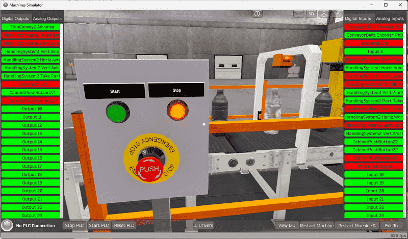
Start the EasyPLC Machine Simulator (MS). Select the start button on the main page or select machines from the main menu at the top of the machine’s simulator window.
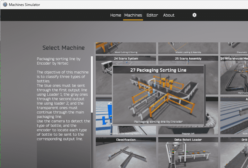
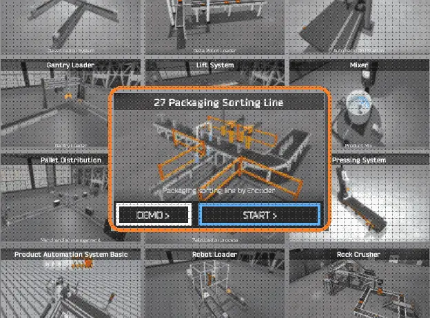
All the available machines will now be displayed. Click on the “27 Packaging Sorting Line.”
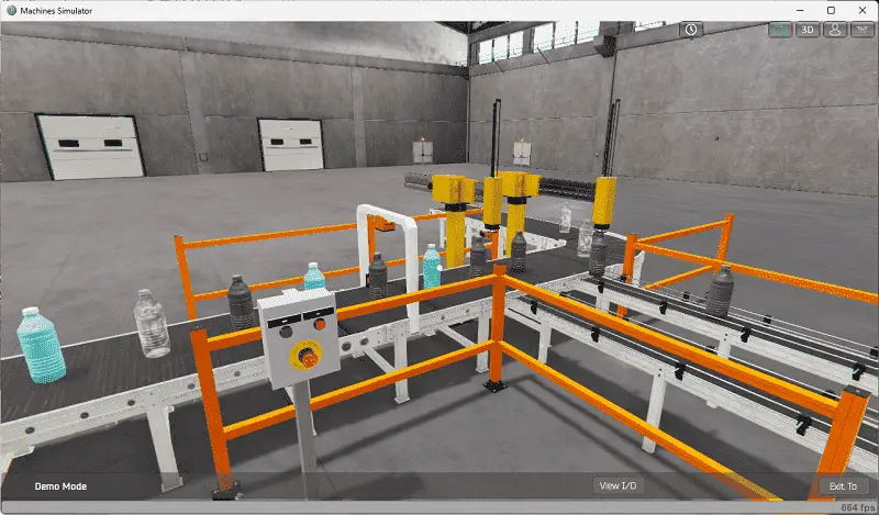
This is the example that we will be programming. To the left of the screen, information will be displayed on how this process needs to function.
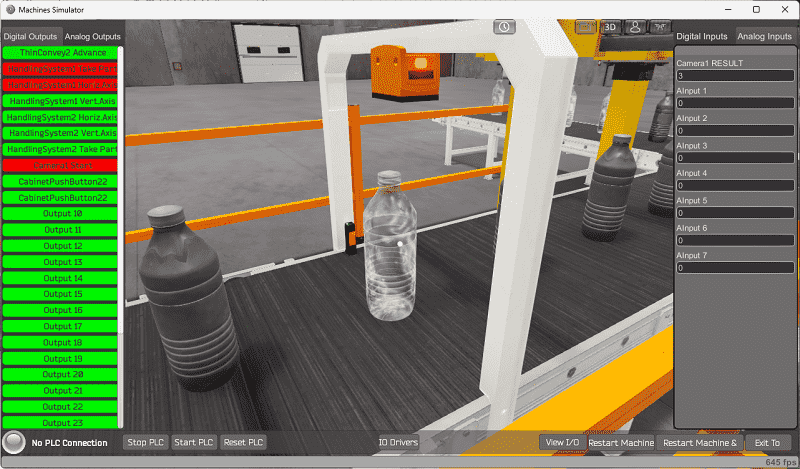
The objective of this machine is to classify three types of bottles: blue, gray, and transparent. The camera detects the bottle type, and the encoder is used to locate every kind of bottle and direct it to the appropriate output line. The blue bottles must be sent through the first output line using Loader 1, the gray bottles through the second output line using Loader 2, and the transparent bottles must continue through the main packaging line.
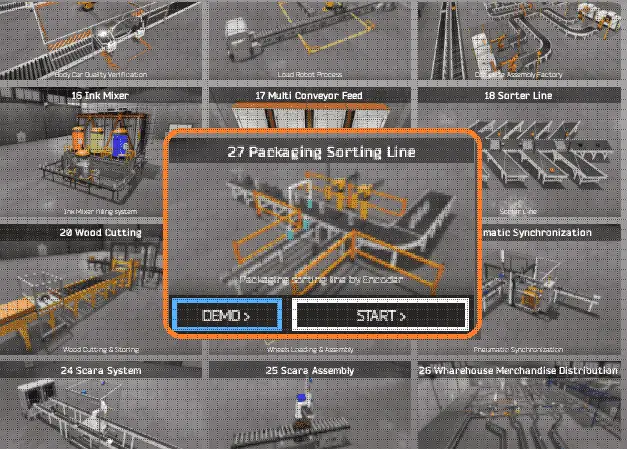
The machine simulator has a demo mode for the built-in machines. This will allow you to watch the operation of the packaging sorting line. Select the demo mode.
The EasyPLC demo mode on the machine simulator will operate, showing you the basics of operation.
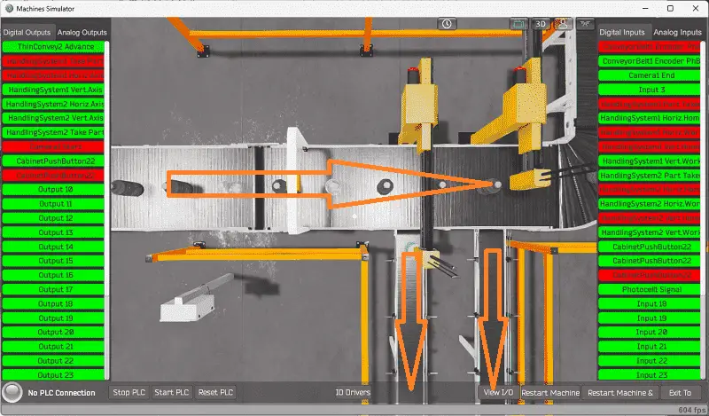
Move around the 3D virtual environment. Three icons on the top of the window will allow you to move around this 3D environment.
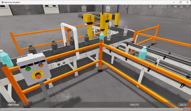
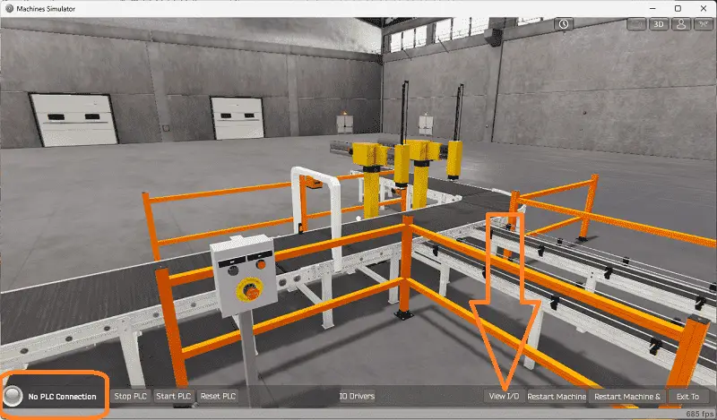
The first-person mode will mimic a person in your 3D learning world. The first icon is the default selection. This will enable you to move around without bumping into the components. The last icon will automatically show you around this virtual environment. Once we understand what must be done, we can move on to the next step in our PLC program development.
Define the Inputs and Outputs: (Step 2 – PLC Programming Sorting Operations)
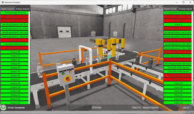
The View IO at the bottom of the machine simulator window will display the inputs and outputs required for this packaging sorting line example. While still in demo mode, you can see the operation of the inputs and outputs.
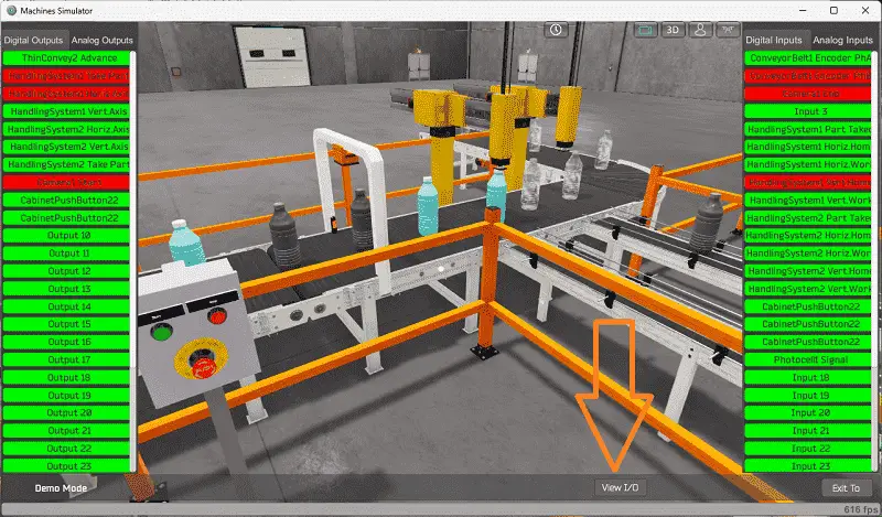
The EasyPLC packaging sorting operations example will require ten digital outputs and 18 digital inputs. It will also need one analog input.
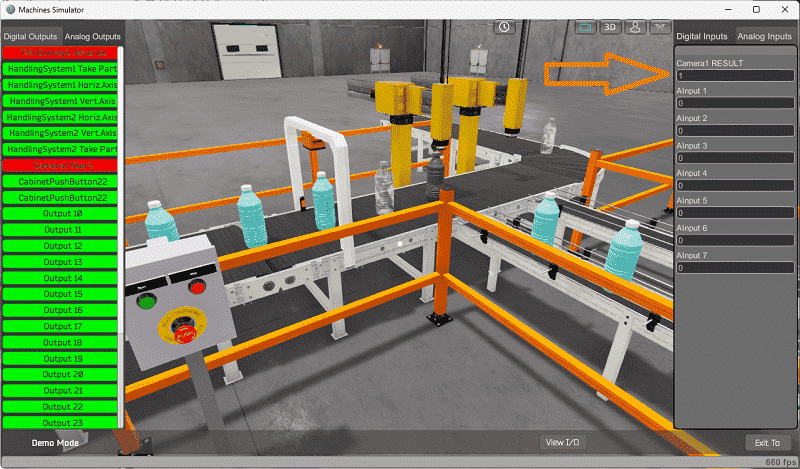
This will be used to determine the bottle color.
The EasyPLC start mode will allow you to manually control the automatic car washing machine. Exit the demo mode and enter the start mode for this machine.
This is ideal if you need clarification on what output or input is doing.
Select the View IO on the bottom middle of the machine simulator window. You can manually run the machine simulator without any control or PLC connection.
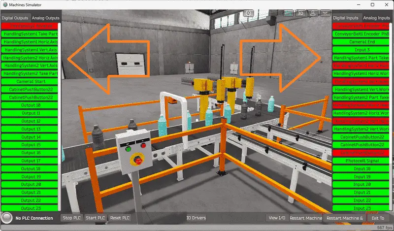
You can now select the packaging line sorting digital outputs on the left side of the screen by clicking on them with the mouse. The right side will show you the corresponding digital inputs.
The restart button on the bottom of the machine simulator window will reset the scene back to the start.
Before programming, you must know the function and operation of each input and output.
The following table will define the inputs and outputs (IO) and Modbus addresses in the Do-More Designer Simulator PLC we will use for this program.
| Digital Type | Description | Do-More PLC Modbus Address | Machine Simulator Modbus Address |
| PLC Output – MS Input | Thin Conveyor Advance | MI1 – 10001 | 0 |
| PLC Output – MS Input | Handling System 1 Take Part | MI2 – 10002 | 1 |
| PLC Output – MS Input | Handling System 1 Horiz. Axis | MI3 – 10003 | 2 |
| PLC Output – MS Input | Handling System 1 Vert. Axis | MI4 – 10004 | 3 |
| PLC Output – MS Input | Handling System 2 Horiz. Axis | MI5 – 10005 | 4 |
| PLC Output – MS Input | Handling System 2 Vert. Axis | MI6 – 10006 | 5 |
| PLC Output – MS Input | Handling System 2 Take Part | MI7 – 10007 | 6 |
| PLC Output – MS Input | Camera 1 Start | MI8 – 10008 | 7 |
| PLC Output – MS Input | Cabinet Pushbutton Start Light | MI9 – 10009 | 8 |
| PLC Output – MS Input | Cabinet Pushbutton Stop Light | MI10- 10010 | 9 |
| PLC Input – MS Output | Conveyor Belt 1 Phase A | MC1 – 1 | 0 |
| PLC Input – MS Output | Conveyor Belt 1 Phase B | MC2 – 2 | 1 |
| PLC Input – MS Output | Camera 1 End | MC3 – 3 | 2 |
| PLC Input – MS Output | Input 3 | MC4 – 4 | 3 |
| PLC Input – MS Output | Handling System 1 Part Taken | MC5 – 5 | 4 |
| PLC Input – MS Output | Handling System 1 Horiz. Home | MC6 – 6 | 5 |
| PLC Input – MS Output | Handling System 1 Horiz. Work | MC7 – 7 | 6 |
| PLC Input – MS Output | Handling System 1 Vert. Home | MC8 – 8 | 7 |
| PLC Input – MS Output | Handling System 1 Vert. Work | MC9 – 9 | 8 |
| PLC Input – MS Output | Handling System 2 Part Taken | MC10 – 10 | 9 |
| PLC Input – MS Output | Handling System 2 Horiz. Home | MC11 – 11 | 10 |
| PLC Input – MS Output | Handling System 2 Horiz. Work | MC12 – 12 | 11 |
| PLC Input – MS Output | Handling System 2 Vert. Home | MC13 – 13 | 12 |
| PLC Input – MS Output | Handling System 2 Vert. Work | MC14 – 14 | 13 |
| PLC Input – MS Output | Cabinet Pushbutton Start | MC11 – 15 | 14 |
| PLC Input – MS Output | Cabinet Pushbutton Stop | MC12 – 16 | 15 |
| PLC Input – MS Output | Cabinet Pushbutton Emergency Stop | MC13 – 17 | 16 |
| PLC Input – MS Output | Photocell Signal | MC14 – 18 | 17 |
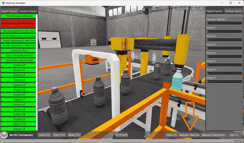
| PLC Analog Input – MS Analog Output | Camera 1 Result | MHR11 – 11 | 10 |
Note: The machine simulator will be offset by one of the Modbus Addresses. See the video below for the demo mode and determining inputs and outputs.
See the video below for the demo mode and determining inputs and outputs.
Develop a logical sequence of operations: (Step 3 – PLC Programming Sorting Operations)
A PLC programmer must know everything about the sequence and operation of the machine before programming. The pneumatic synchronization simulator is an excellent way to learn to program. Flow charts or sequence tables can be used to understand the process that needs to be controlled thoroughly. It must also answer questions like the following:
What happens when electrical power or pneumatic air is lost? What happens when the input/output devices fail? Do we need redundancy?
This step is where you will spend most of your time. Understanding everything about the operation will save you time. It will help prevent you from continuously re-writing the PLC program logic. Knowing all these answers to how the system is to react is vital in developing the PLC program. This does not have to be a formal document. You must have a method to account for every condition in the machine being programmed.
Our machine has a control panel with lighted push buttons. If the machine is stopped and ready to be started, the start pushbutton light will flash. If the machine is running, the red stop light will be on. If both lights are off, the emergency stop has been pressed.
The packaging sorting operations is reset if the stop button is pressed within 0.8 seconds twice.
The conveyors all run together. This includes the main and the two sorted conveyors. The conveyors are started and stopped by the control panel or if the correct color bottle is positioned under the pick and place robot for the exit conveyor. After the bottle is transferred, the conveyors will then start again.
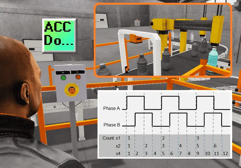
Bottle colors are determined by a camera located on the main conveyor. A photocell and an end camera signal will be activated when a bottle has been determined. An encoder is used on the conveyor to track the bottles. This encoder provides two outputs that pulse.
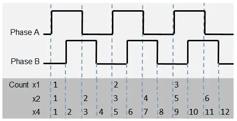
This encoder is wired to the inputs. Phase A and B are used to determine direction. If phase A leads B by 90 degrees, the encoder moves one way. If phase B leads A by 90 degrees, the encoder moves the other way.
In our application, the direction does not matter. However, we can use the leading and trailing edges of the encoder phase pulses to increase the accuracy of our belt movement.
Since the encoder is mechanically linked to the main conveyor, the pulses represent the movement of the conveyor.
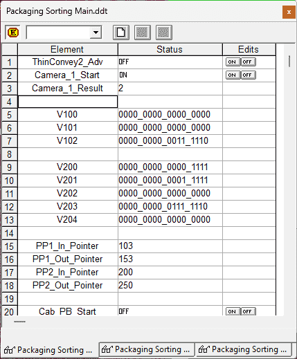
A shift register is used to track the bottles along the main conveyor. Since we have two exit conveyors, the blue and grey bottles will have their shift registers. A bit within each shift register will represent the distance to the corresponding pick and place robot.
The two robots can be easily viewed using a sequence table.
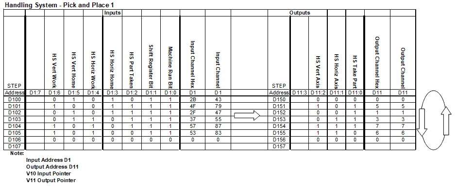
At first, sequence tables may seem confusing; however, the sequence table is read from left to right. If the input conditions are met, the output conditions are set. You will see that each of the tables is similar. This is because they perform the same task. The PLC programming will involve address pointers. This is sometimes referred to as indirect addressing. I have assigned PLC addresses to the pointers, input, and output tables.
A PLC programmer must know how everything about the sequence and operation of the machine before programming.
Ensuring you know what must happen will help clarify what is required in the PLC program. Ask questions or view existing documentation to ensure that you know the logical steps to the machine’s operation. This may involve speaking with the manufacturer, operators, engineers, etc.
Develop the Do-More PLC program: (Step 4 – PLC Programming Sorting Operations)
Using the information from the previous steps, we can now program our Do-More PLC Simulator. The BRX Do-More PLC Series will take you through installing the program, communicating with the controller, providing instructions, and addressing the controller.
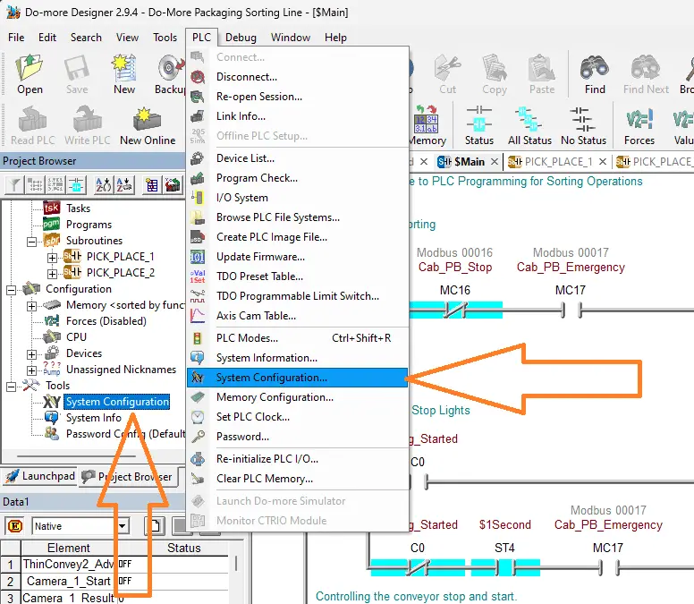
Select the system configuration under PLC on the main menu. You can also call this up by selecting system configuration under the tools menu in the project browser window.
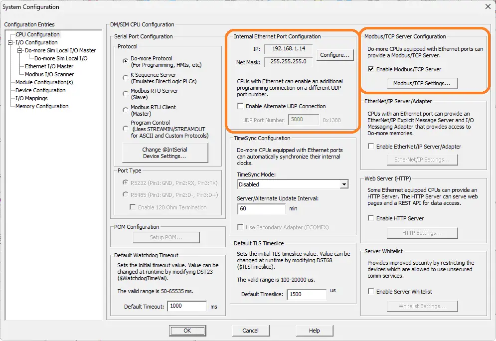
The computer’s IP address can be seen under the “Internal Ethernet Port Configuration.”
Modbus TCP Server is selected by default; however, we can also ensure this is the case in the system configuration window.
Our PLC is now a Modbus TCP Server to the EasyPLC Modbus TCP Client. Please make a note of the static IP address that we are using for the BRX Do-More PLC. This will be used later to connect to the EasyPLC machine simulator.
The ladder logic plc programming is split up so that it is easier to read and program. We have subroutines for the pick-and-place robots. These will control the robot’s sequencer inputs, outputs, and logical stepping. The main program will call these subroutines and the rest of the ladder logic program for the sorting operations.
Main Ladder Logic Program
An internal bit (C0) is used to start the sorting operations. A start-stop circuit is used to control this bit.
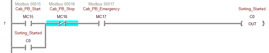
The emergency pushbutton is normally closed coming into the PLC, shown as a normally open contact on our ladder logic rung.
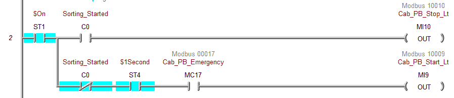
The pushbutton lights are controlled based on the internal sorting started bit. If the emergency PB is pressed, this will cause both the start and stop lights to turn off. The stop light on the push button is on when the machine is running. When the machine stops, the green-lighted pushbutton will flash, indicating the sorting operations can start.
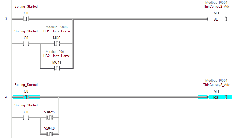
The conveyor belt is controlled by the set and resets instructions. They are controlled by the start-stop operator panel and when the bottles are under the pick and place robots. Stopping the robot happens when the leading edge of the shift bits is detected for both exit conveyors. This is determined by the number of pulses coming from the encoder input. The conveyor starts again on the horizontal home bit leading edge.
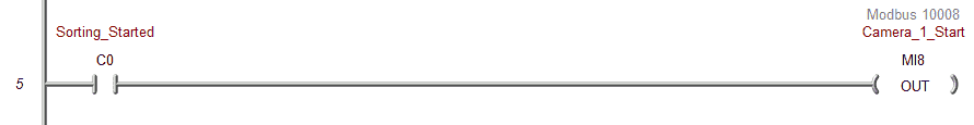
The camera will start when the internal sorting operations bit is activated.
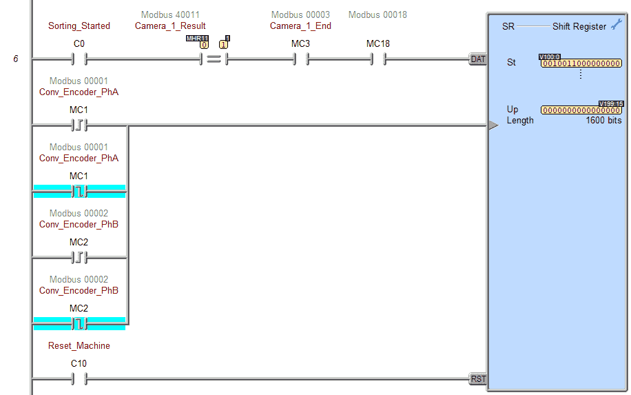
A shift register is used to track the bottles on the conveyor belt. The first input line or data to the register comes from the camera end bit, the photo eye sensor, and when the camera result has the value of 1. The 1 represents the blue bottle.
The clock pulse bits for the shift register are the encoder leading and trailing edges. As mentioned, each clock pulse input represents a distance on the conveyor belt.
The reset machine’s internal bit will reset all of the bits in the shift registers. Register bits V100:00 to V199:15 are used for the first pick-and-place robot.
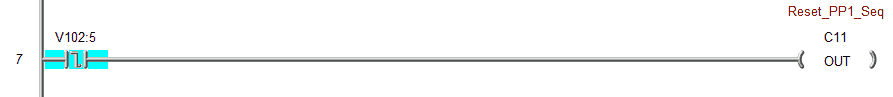
The trailing edge of the bit that triggers the first pick and place robot is used to trigger a reset for its sequencer operation.
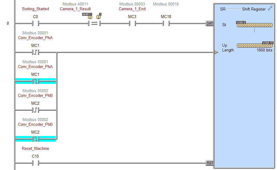
Another shift register tracks the bottles when the camera detects a grey bottle. This is for the second exit conveyor belt and robot. Register bits V200:00 to V299:15 are used for the second pick-and-place robot.

The trailing edge of the bit that triggers the second pick and place robot is used to trigger a reset for its sequencer operation.
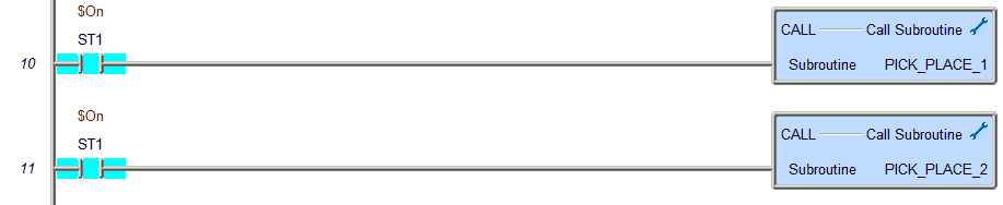
Subroutines for the pick and place robots are called every scan of the PLC.
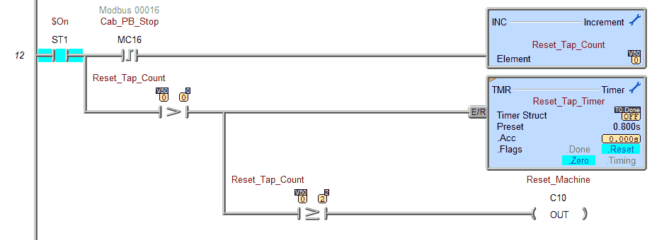
The machine reset bit is turned on if the stop pushbutton is pressed twice within 0.8 seconds. This will reset the shift registers and the robot sequencers.
The leading edge of the stop pushbutton is used to increment a register. If this register is greater than 0, a timer is started. The reset machine bit turns on if the register is greater than or equal to 2.
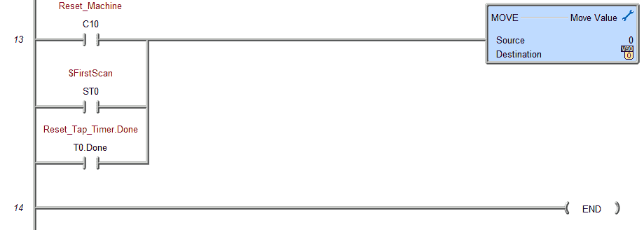
If the reset machine bit turns on, the tap timer is done, or on the first scan, the tap count register will be reset.
This is the end of the Main PLC programming section.
The pick and place robot sequencers are both similar and are programmed based on the information from the sequence tables created.
Pick Place 1 Subroutine
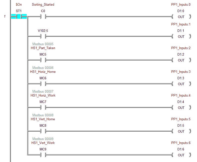
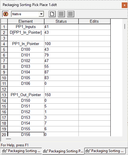
The actual PLC inputs are used to set up the input register for the sequencer. (D1)
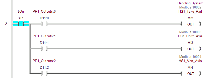
The output register (D11) sets the actual PLC outputs for the sorting operations.
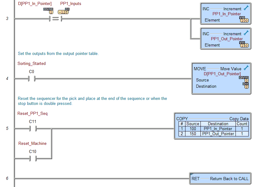
When the actual inputs equal the sequence table input, the input and output pointers are incremented by one. The output sequence table data is sent indirectly to the outputs.
When the machine or sequencer reset is activated, the pointers are reset back to the starting values.
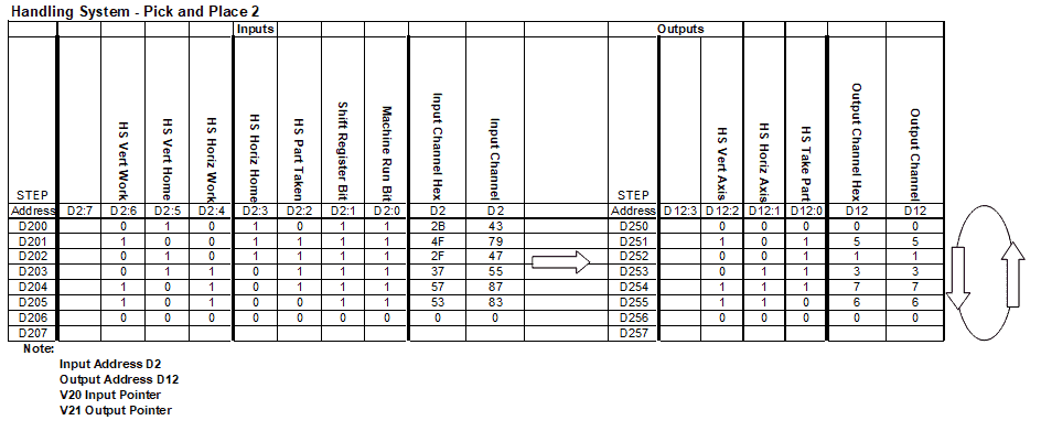
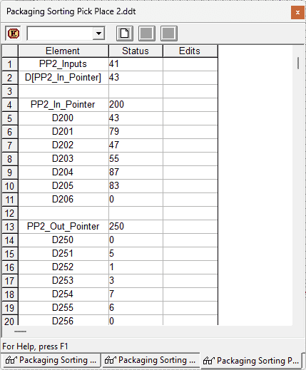
Pick Place 2 Subroutine
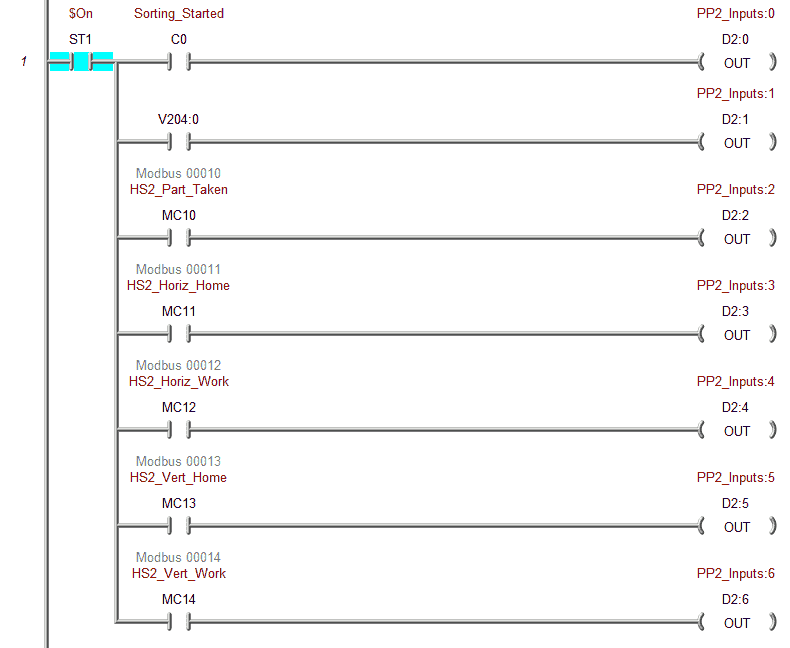
The actual PLC inputs are used to set up the input register for the sequencer. (D2)
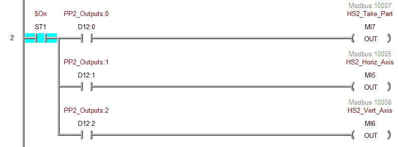
The output register (D12) sets the actual PLC outputs for the sorting operations.

When the actual inputs equal the sequence table input, the input and output pointers are incremented by one. The output sequence table data is sent indirectly to the outputs.
When the machine or sequencer reset is activated, the pointers are reset back to the starting values.
Our ladder logic PLC program is complete. Download this to the Do-More Designer Simulator and ensure that the simulator is in run mode.
Watch the video below to see this BRX Do-More PLC program in action.
Test the program: (Step 5 – PLC Programming Sorting Operations)
We will use Modbus TCP on our Do-More PLC simulator to communicate with the EasyPLC Machine Simulator.
Call up the “27 Packaging Sorting Line” machine in start mode.
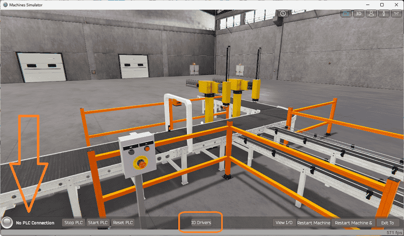
The status of the machine simulator will be at the bottom of the screen. Currently, we have no PLC connected. Select IO Drivers on the bottom middle of the screen.
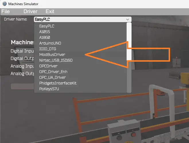
The EasyPLC driver is selected by default. Under the driver pull-down menu, select “ModBusDriver.” This driver will communicate Modbus TCP (Ethernet) and Modbus RTU (Serial). Select the down arrow on the driver’s name.
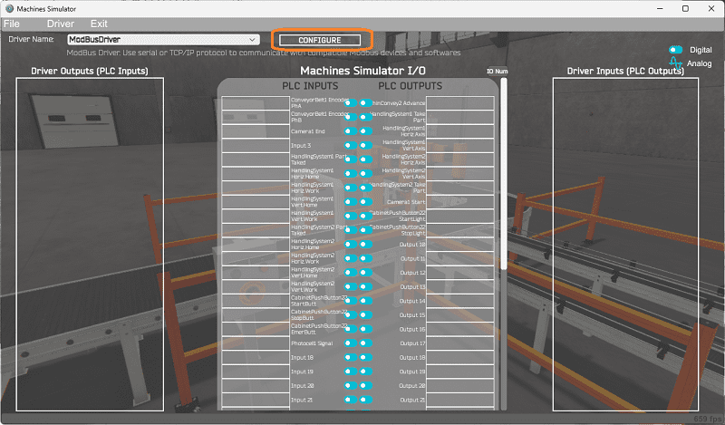
Select the configure button.
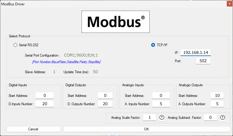
We can now enter the information for our Modbus driver. Select TCP/IP. This means the Ethernet port on the computer will communicate with the PLC.
The digital inputs from MS to the Do-More PLC will be MC1 to MC18. This will start at address 0 due to the offset of 1. Digital outputs from MS to the Do-More PLC will be MI1 to MI0. This will begin at address 0 due to the offset of 1. We are indicating 20 digital inputs and outputs. This is fine because it is more than our EasyPLC machine simulator will require.
Analog inputs from MS to the Do-More PLC will be MHR11. Due to the offset of 1, the PLC analog will start at addresses 10.
Select the OK button.
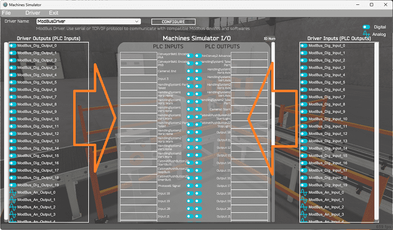
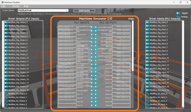
You will now see the inputs and outputs specified for the Modbus driver. We can manually assign the driver outputs to the PLC inputs and the driver inputs to the PLC outputs. However, the automatic assignment works well and will save you time.
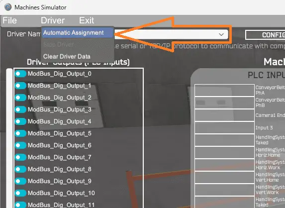
Select Automatic Assignment from the driver option in the main menu.
This will automatically assign the PLC IO to the Machine Simulator IO.
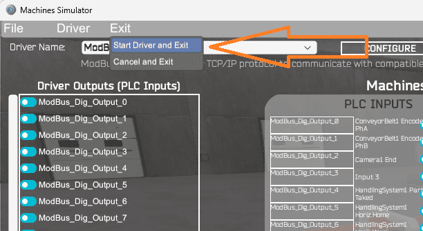
Select start driver and exit from the main menu.
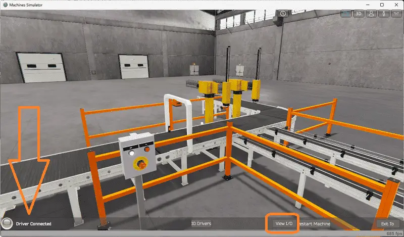
On the bottom left side of the window, you will see that the driver communicates to the PLC with the green light. Select view IO to know the input and output status of the machine simulator.
Ensure that the PLC is in run mode. We can now operate our EasyPLC sorting operations machine.
Using the Data View window of the Do-More Designer programming software, we can also watch the inputs and outputs operate.
Watch the video below to see this operation.
If your program works correctly, it’s time to move on. If not, you’ll need to debug. Since we are using indirect addressing, troubleshooting, and modifications can easily be accomplished. This can be as simple as re-downloading and re-uploading your program or as complicated as re-designing your logic altogether. Amendments to the sequence table and the corresponding PLC sequence tables will quickly change how your logic works. If the sequencer stops at a location, you can quickly see what inputs should be enabled and what is currently set. This can be displayed on an HMI for troubleshooting.
When using EasyPLC, debugging is quickly done with no damage to any equipment. You may modify your logic several times before you get everything right! That’s okay—it’s all part of learning. After all: trial and error are often easier said than done! To learn more about developing logic, check out our tutorials on the five steps to PLC program development.
You can practice your modification and debug by modifying the sorting operations in the following way:
– Calculate the cycle time in parts per minute for the machine.
– Add a jogging circuit for the sequencer. This will allow the operator to manually step through the sequence to troubleshoot the logic and machine.
Let me know how you make out in the comments below.
Download the Do-More PLC sample program and sequence tables here.
Watch the video below to see the five steps of program development applied to the pneumatic synchronization machine. The machine simulator is one of the best applications to help you learn PLC programming.
EasyPLC Software Suite is a complete PLC, HMI, and Machine Simulator package. This PLC learning package includes the following:
Easy PLC – PLC Simulation allows programming in Ladder, Grafcet, Logic Blocks, or Script.
HMI System – Easily create a visual human-machine interface (HMI)
Machine Simulator – A virtual 3D world with real-time graphics and physical properties. PLC programs can be tested using EasyPLC or through other interfaces. (Modbus RTU, TCP, etc.)
Machine Simulator Lite – Designed to run on Android Devices.
Machine Simulator VR – Virtual Reality comes to life so you can test, train or practice your PLC programming.
Purchase your copy of this learning package for less than USD 75 for a single computer install or less than USD 100 to allow different computers.
Receive 10% off the price by typing in ACC in the comment section when you order. http://www.nirtec.com/index.php/purchase-price/
Learn PLC programming the easy way. Invest in yourself today.
Watch on YouTube: The Ultimate Guide to PLC Programming for Sorting Operations
If you have any questions or need further information, please get in touch with me.
Thank you,
Garry
If you’re like most of my readers, you’re committed to learning about technology. Numbering systems used in PLCs are not challenging to learn and understand. We will walk through the numbering systems used in PLCs. This includes Bits, decimals, Hexadecimal, ASCII, and Floating points.
To get this free article, subscribe to my free email newsletter.
Use the information to inform other people how numbering systems work. Sign up now.

The ‘Robust Data Logging for Free’ eBook is also available for free download. The link is included when you subscribe to ACC Automation.