Multi-conveyor feed control is a critical aspect of industrial automation that allows for the efficient and effective movement of materials from one process to another. It involves the coordination of multiple conveyors to ensure that the right amount of material is transferred at the right time to the next stage in the manufacturing process. Bottlenecks, delays, and wasted resources can result without this ability. PLC programming is a key tool used to achieve this level of control, as it allows for the precise management of conveyor speeds and material flow, ensuring that the manufacturing process operates at maximum efficiency.
The five steps for PLC program development will be followed in our example to ensure a successful implementation. This will guide you in creating this multi-feed conveyor control operation. EasyPLC will be connected to a Click PLC using Modbus TCP (Ethernet). An operator panel with a start and stop, lighted pushbuttons, will control this conveyor system. Let’s get started.
Learn PLC programming the easy way. See below for a 10% discount on this cost-effective learning tool. Invest in yourself today.
Previously we have done the following:
Easy PLC Installing the Software – Video
EasyPLC Software Suite – Quick Start – Video
Click PLC – Easy Transfer Line Programming – Video
Productivity PLC Simulator – Chain Conveyor MS – Video
Do-More PLC – EasyPLC Box Selection Program – Video
Click PLC EasyPLC Gantry Simulator – Video
Click PLC Simple Conveyor EasyPLC – Video
EasyPLC Paint Line Bit Shift – BRX Do-More PLC – Video
Click PLC – EasyPLC PLC Mixer Programming – Video
Click PLC EasyPLC Warehouse Stacker Example – Video
– Operation Video
EasyPLC Machine Simulator Productivity PLC Robotic Cell – Video
EasyPLC Simulator Robotic Cell Click PLC – Video
EasyPLC Simulator Robotic Cell BRX Do-More PLC – Video
– EasyPLC Factory Editor Robotic Cell Additions Video
4 Way Traffic Light PLC Program EasyPLC – Video
Rock Crusher Plant EasyPLC BRX Do-More – Video
Freight Carrier Weighing and Distribution EasyPLC – Video
EasyPLC Machining Center Loading Robots – Video
EasyPLC Palletizing Robot Programming Click PLC – Video
EasyPLC Machine Editor – Design a Simulation – Video
PLC Programming Mixing Tank – EasyPLC / Do-More – Video
EasyPLC Solder Robot PLC Programming – Video
PLC Programming – A Tutorial for Beginners – Video
Automated Parking Demo Video
Parking Cars Simulator PLC Programming Part 1 – Video
Parking Cars Simulator PLC Programming Part 2 – Video
PLC Programming with Pneumatic Synchronization – Video
The Ultimate Guide to PLC Programming for Sorting Operations – Video
Optimizing Batch Processing with PLC Systems – Video
Define the task: (Step 1 – PLC Multi Conveyor Feed Control)
The first step of PLC program development is to define the task to determine what must be done. EasyPLC software suite contains this multi-feed conveyor example in the machine simulator. This is just one of many machines with the software so you can learn and develop your PLC programming skills.
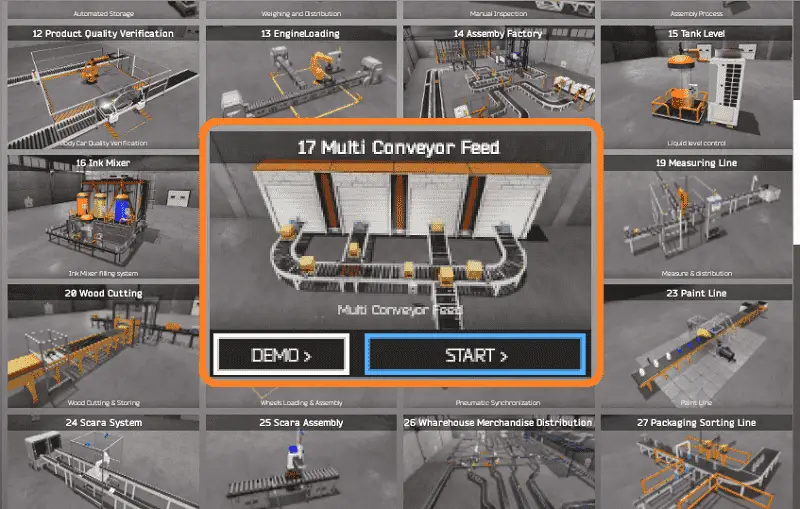
Start the EasyPLC Machine Simulator (MS). Select the start button on the main page or select machines from the main menu at the top of the machine’s simulator window.
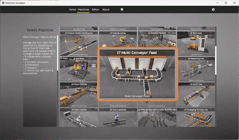
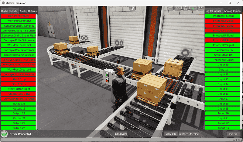
All the available machines will now be displayed. Click on the “17 Multi Conveyor Feed.”
This is the example that we will be programming. To the left of the screen, information will be displayed on how this process needs to function.
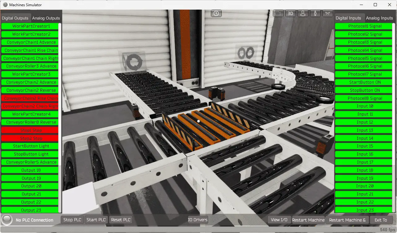
Manage the four input lines of materials to, depending on the arrival of materials, distribute the output orderly through a single output line.
– 8 independent conveyor lines
– 2 transfer conveyors
– 8 photocells
– 2 stoppers
– 1 control box with a start and stop buttons
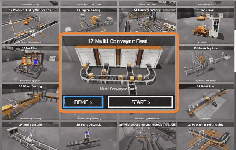
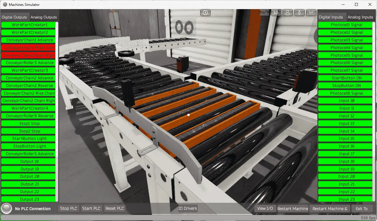
The machine simulator has a demo mode for the built-in machines. This will allow you to watch the operation of the packaging sorting line. Select the demo mode.
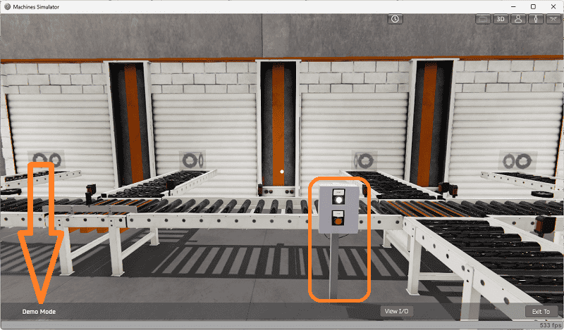
The EasyPLC demo mode on the machine simulator will operate, showing you the basics of operation.
Move around the 3D virtual environment. The icons on the top of the window will allow you to move around this 3D environment.
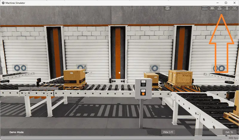
The first icon is the default selection. This will enable you to move around without bumping into the components. The first-person mode will mimic a person in your 3D learning world.
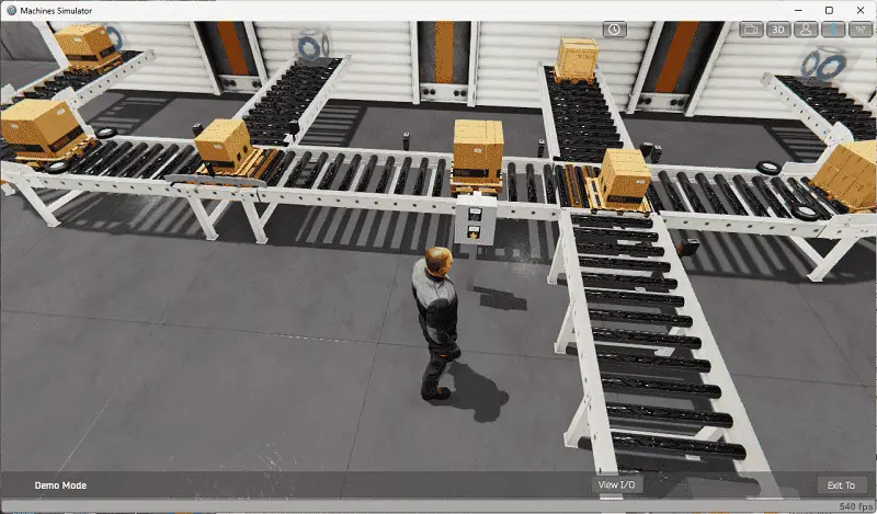
The third person is used to show the operator’s relationship to the machine. The last icon will automatically show you around this virtual environment. Once we understand what must be done, we can move on to the next step in our PLC program development.
Define the Inputs and Outputs: (Step 2 – PLC Multi Conveyor Feed Control)
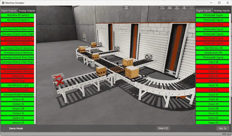
The View IO at the bottom of the machine simulator window will display the inputs and outputs required for this packaging sorting line example. While still in demo mode, you can see the operation of the inputs and outputs.
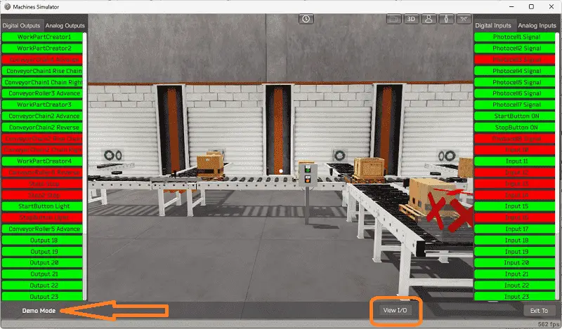
The EasyPLC multi-conveyor feed example will require 18 digital outputs and ten digital inputs.
The EasyPLC start mode will allow you to control this sorting operations machine manually. Exit the demo mode and enter the start mode for this machine.
This is ideal if you need clarification on what output or input is doing.
Select the View IO on the bottom middle of the machine simulator window. You can manually run the machine simulator without any control or PLC connection.
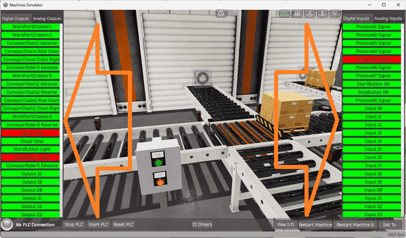
You can now select the multi-conveyor feed digital outputs on the left side of the screen by clicking on them with the mouse. The right side will show you the corresponding digital inputs.
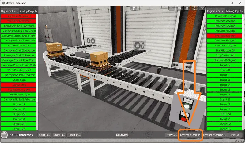
The restart button on the bottom of the machine simulator window will reset the scene back to the start.
Move around the 3D environment and ensure you know what each input and output represents.
The following table will define the inputs and outputs (IO) and Modbus addresses in the Click PLC we will use for this program.
| Digital Type | Description | Click PLC Modbus Address | Machine Simulator Modbus Address |
| PLC Output – MS Input | Work Part Creator 1 | C101 – 16485 | 16484 |
| PLC Output – MS Input | Work Part Creator 2 | C102 – 16486 | 16485 |
| PLC Output – MS Input | Conveyor Chain 1 Advance | C103 – 16487 | 16486 |
| PLC Output – MS Input | Conveyor Chain 1 Rise | C104 – 16488 | 16487 |
| PLC Output – MS Input | Conveyor Chain 1 Right | C105 – 16489 | 16488 |
| PLC Output – MS Input | Conveyor Roller 3 Advance | C106 – 16490 | 16489 |
| PLC Output – MS Input | Work Part Creator 3 | C107 – 16491 | 16490 |
| PLC Output – MS Input | Conveyor Chain 2 Advance | C108 – 16492 | 16491 |
| PLC Output – MS Input | Conveyor Chain 2 Reverse | C109 – 16493 | 16492 |
| PLC Output – MS Input | Conveyor Chain 2 Rise | C110 – 16494 | 16493 |
| PLC Output – MS Input | Conveyor Chain 2 Right | C111 – 16495 | 16494 |
| PLC Output – MS Input | Work Part Creator 4 | C112 – 16496 | 16495 |
| PLC Output – MS Input | Conveyor Roller 8 Reverse | C113 – 16497 | 16496 |
| PLC Output – MS Input | Stop 1 | C114 – 16498 | 16497 |
| PLC Output – MS Input | Stop 2 | C115 – 16499 | 16498 |
| PLC Output – MS Input | Start Button Light | C116 – 16500 | 16499 |
| PLC Output – MS Input | Stop Button Light | C117 – 16501 | 16500 |
| PLC Output – MS Input | Conveyor Roller 5 Advance | C118 – 16502 | 16501 |
| PLC Input – MS Output | Photocell Signal 1 | C201 – 16585 | 16584 |
| PLC Input – MS Output | Photocell Signal 2 | C202 – 16586 | 16585 |
| PLC Input – MS Output | Photocell Signal 3 | C203 – 16587 | 16586 |
| PLC Input – MS Output | Photocell Signal 4 | C204 – 16588 | 16587 |
| PLC Input – MS Output | Photocell Signal 5 | C205 – 16589 | 16588 |
| PLC Input – MS Output | Photocell Signal 6 | C206 – 16590 | 16589 |
| PLC Input – MS Output | Photocell Signal 7 | C207 – 16591 | 16590 |
| PLC Input – MS Output | Start Button ON | C208 – 16592 | 16591 |
| PLC Input – MS Output | Stop Button ON | C209 – 16593 | 16592 |
| PLC Input – MS Output | Photocell Signal 8 | C210 – 16594 | 16593 |
Note: The machine simulator will be offset by one on the Modbus Addresses. See the video below for the demo mode and determining inputs and outputs.
Develop a logical sequence of operation: (Step 3 – PLC Multi Conveyor Feed Control)
A PLC programmer must know everything about the sequence and operation of the machine before programming. The sorting operation simulator is an excellent way to learn to program. Flow charts or sequence tables can be used to understand the process that needs to be controlled thoroughly. It must also answer questions like the following:
What happens when electrical power or pneumatic air is lost? What happens when the input/output devices fail? Do we need redundancy?
This step is where you will spend most of your time. Understanding everything about the operation will save you time. It will help prevent you from continuously re-writing the PLC program logic. Knowing all these answers to how the system reacts is vital in developing the PLC program. This does not have to be a formal document. You must have a method to account for every condition in the machine being programmed.
Our machine has multiple conveyors. We have several roller conveyors and two chain conveyors.
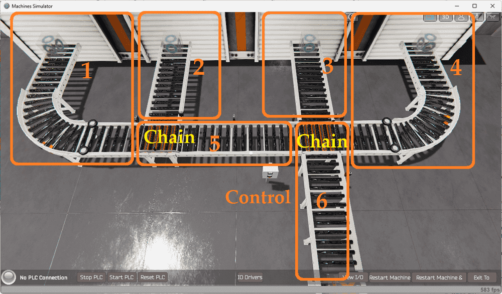
We have broken this machine into several sections. This allows us to simplify each section of the line. The control panel has lighted push buttons. If the machine is stopped and ready to be started, the start pushbutton light will flash. If the machine is running, the red stop light will be on.
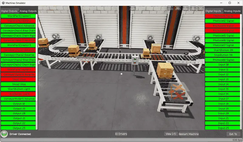
When the machine is started, skids of material will appear on conveyors 1 to 4. The program’s purpose is to move these skids to the output line. (Section 6)
Chain conveyor 2 will control the skids of material from three different feeding conveyors and send them down the output conveyor. The material will alternate between the different feeding conveyors. Stoppers are used to ensure that the skids will not collide with each other.
Chain conveyor 1 will control the skids of material from sections 1 and 2 and send them onto chain conveyor 2. If material is present on both 1 and 2, the skids will alternate being sent.
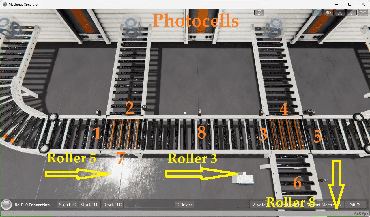
Photocells are used to indicate the skid of the material. This will allow the PLC to determine the location of the skid or when it will arrive. Roller 5 moves the skids to chain conveyor 1. Roller 3 moves the skid from chain conveyor 1 to 2. Roller 8 will be used as the exit conveyor.
A PLC programmer must know how everything about the sequence and operation of the machine before programming.
Ensuring you know what must happen will help clarify what is required in the PLC program. Ask questions or view existing documentation to ensure you understand the logical steps to the machine’s operation. This may involve speaking with the manufacturer, operators, engineers, etc. Create your sequence of operations based on the information above.
Develop the Click PLC program: (Step 4 – PLC Multi Conveyor Feed Control)
Using the information from the previous steps, we can now program our Click PLUS PLC. The Click PLC Series will take you through installing the program, communicating with the controller, providing instructions, and addressing the controller.
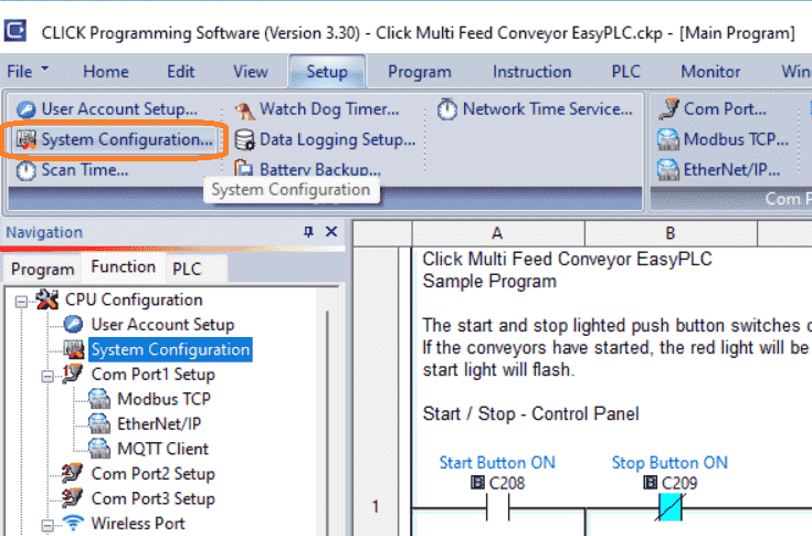
Select the system configuration under Setup on the main menu. You can also call this up by selecting system configuration under the navigation menu in the function tab.
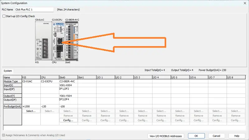
The PLC system configuration can now be seen with the physical addresses of the controller. Double-click on the Ethernet port 1 of the CPU.
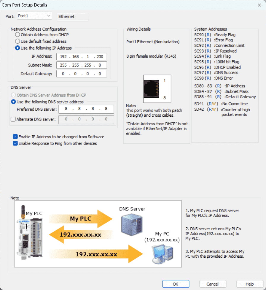
This is the Com Port Setup Details window. We have manually set up the Ethernet port with an IP address for our network.
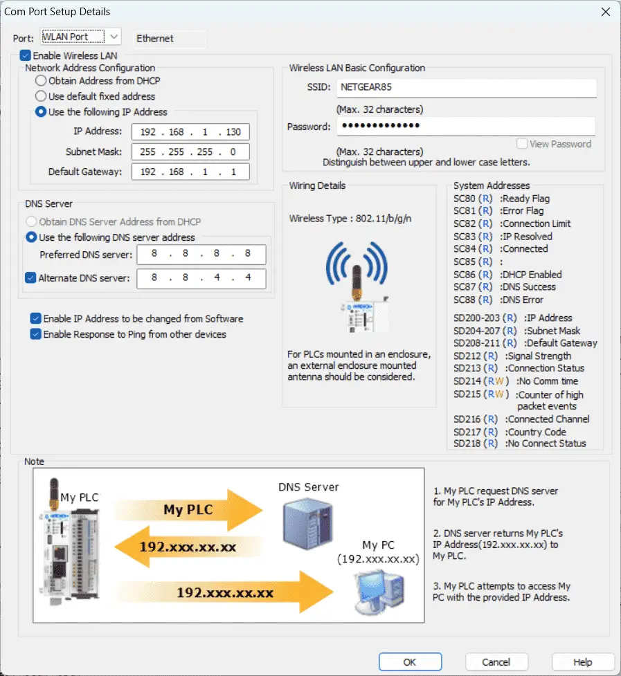
Select the WLAN Port. This is also set up manually for our network using WiFi.
Our PLC is a Modbus TCP Server to the EasyPLC Modbus TCP Client. Please note these static IP addresses we use for the Click PLC. This will be used later to connect to the EasyPLC machine simulator.
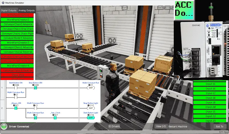
We can now look at the ladder logic program of our Click PLC for our multi-conveyor feed machine. This will also explain the logic as we look at the program.
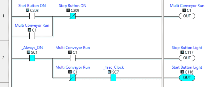
C1 internal bit is used to start the multi-conveyor run. A start-stop circuit is used to control this bit.
Rung 2 will control the pushbutton lights. If C1 is on, then the stop button light will be on solid. If C1 is off, the start button light will flash every second.
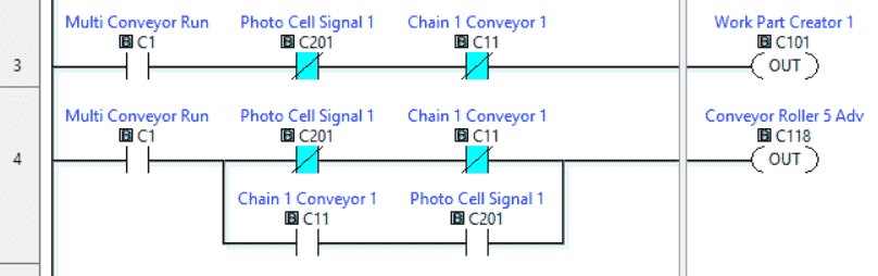
Work Part Creator 1 will create a skid of material on roller conveyor 1. This will be on when the machine is running, photocell 1 is not on, and the chain 1 conveyor is not calling for a skid from the first feed. Roller 5 advance has the same conditions as the previous rung and two additional contacts. This is used to move the skid to the Chain 1 conveyor.
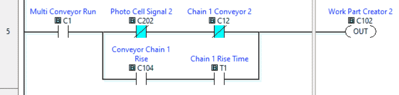
Work Part Creator 2 will be run if the run signal is on, we do not have the photocell 2 input, and the chain 1 conveyor 2 signal is not on. When the chain 1 conveyor signal is on, chain 1 will rise for the rise time. This will also activate the part creator 2 signal.
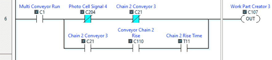
Work Part Creator 3 will be run if the run signal is on, we do not have the photocell 4 input, and the chain 2 conveyor 3 signal is not on. When the chain 2 conveyor 3 signal is on, and chain 2 has risen with time, the work part creator 3 will also be on. This will move the skid to chain 2.
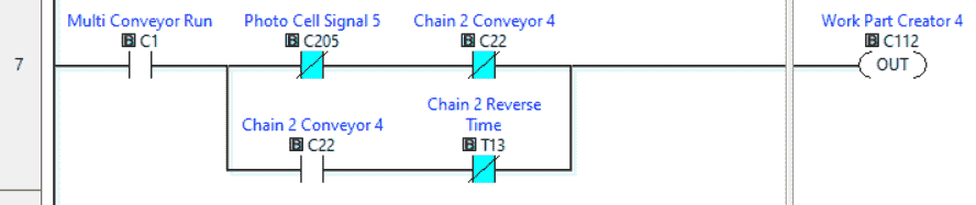
Work Part Creator 4 will be run if the run signal is on, we do not have the photocell 5 input, and the chain 2 conveyor 4 signal is not on. When the chain 2 conveyor 4 signal is on, and the chain 2 reverse time is not done, the work part creator will also activate the output. This moves the skid onto the chain 2 conveyor.
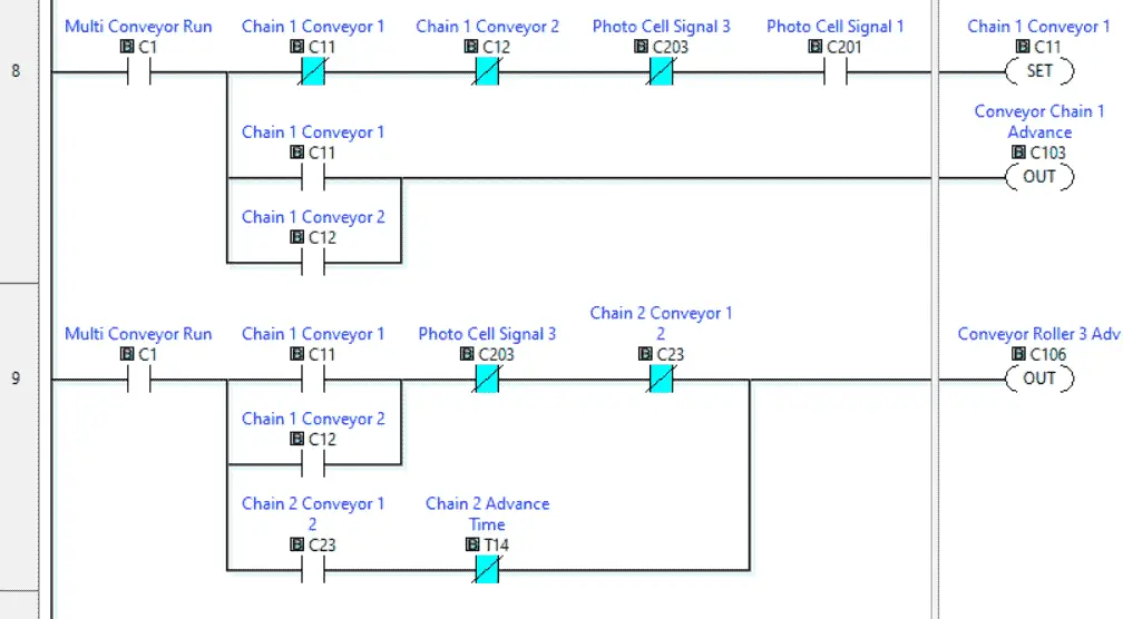
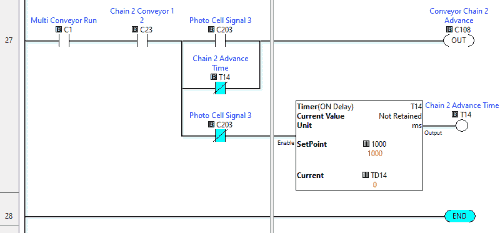
Chain 1 conveyor 1 signal will indicate one of the two methods to bring a skid onto the chain 1 conveyor. The conveyor chain 1 advance will be on if either method is on.
Roller 3 is used to move the skid from chain 1 to chain 2 conveyor. If photocell 3 is off and chain 2 conveyor 1 is not on, then this will advance roller 3. Chain 2 conveyor 1 2, not chain 2 advance time will also active roller 3. This moves the skid onto chain 2.
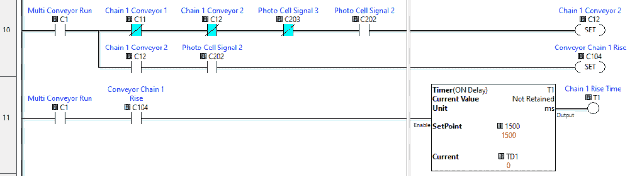
Rung 10 will control the chain 1 conveyor 2 bit. This chain 1 conveyor rise moves the conveyor to the same level as the work part creator 2 conveyor. A timer ensures that the conveyor has risen before any other movement.
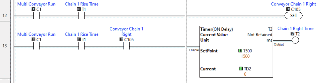
After the chain rises, it must then transport the skid. The timer ensures that the box has traveled to the correct location.
Note: Photocell 7 can also be used instead of the timer.
The conveyor rises, and the right will reset once the right timer has expired and we no longer have the photocell 2 signal.
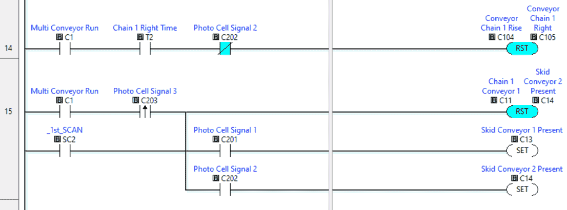
Rung 15 will reset the chain signals once the skid is detected at the end of roller 3 by photocell 3. When this happens, the program will set the next skid to be loaded onto the chain 1 conveyor. This ensures that we will alternate the skid source to this chain conveyor.
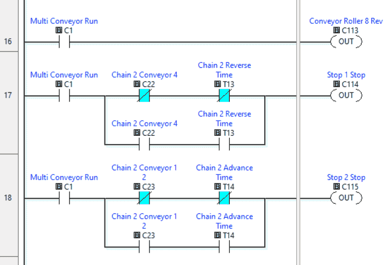
When the multi conveyor runs, the roller 8 output conveyor will always be running. This moves the skids away to the next operation.
Stop 1 and 2 are used with the chain 2 conveyor. They are always activated except when moving a skid from chain 2 conveyor 4 or chain 2 conveyor 1 2. A timer is used for the reverse and advanced on the chain to move the skid onto the chain 2 conveyor.
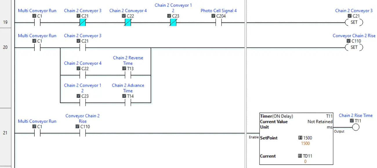
When chain 2 conveyor 3 is set, we need to raise chain 2 conveyor to the same level to get and output the skid. The rising will also happen when the skid gets loaded from chain 2 conveyor 4 or 1 2. A timer is used on the rise to ensure it is at full height.
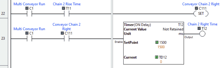
Once chain 2 has risen, chain 2 right will be activated for a timed period to ensure the skid has moved off-chain 2.
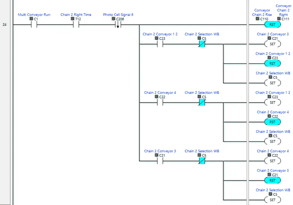
When the chain 2 right timer is finished, and photocell 6 sees the tailing edge of the output skid, the chain 2 conveyor rises, and the right will reset.
Based on which feed conveyor is ready, the previous one will be reset, and the next will be set. This ensures that the conveyors will be cycled through.
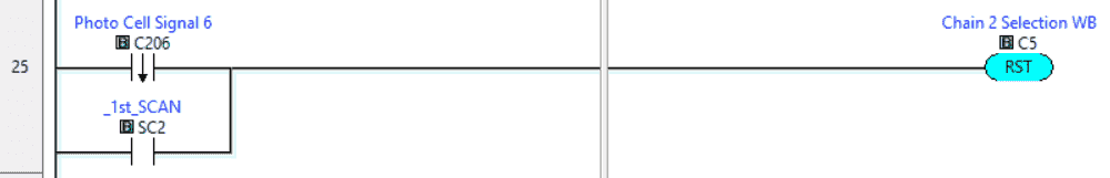
The trailing edge of Photocell 6 will also reset the chain selection work bit. This is used so that only one of the previous selections is made with the one shot.
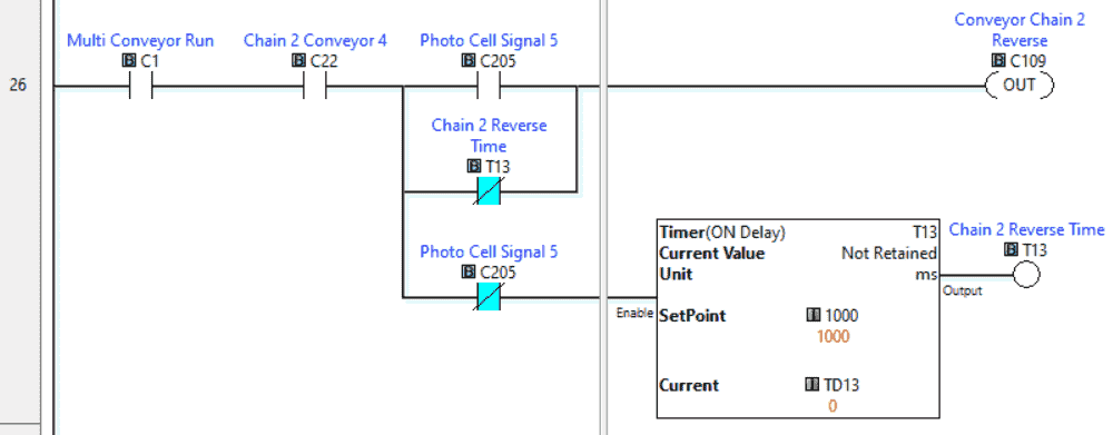
Chain 2 reverse will load a skid from conveyor 4 to the chain. This is on for a timed value after photocell 5 turns off.
Chain 2 advance will load a skid from conveyor 1 2 to the chain. This is on for a timed value after Photocell 3 turns off.
Our ladder logic PLC program is complete. Download this to the click PLC with the Click Programming Software and ensure that the PLC is in run mode.
Watch the video below to see this Click PLC program in action.
Test the program: (Step 5 – PLC Multi Conveyor Feed Control)
We will use Modbus TCP on our Click PLC to communicate with the EasyPLC Machine Simulator.
Call up the “27 Packaging Sorting Line” machine in start mode.
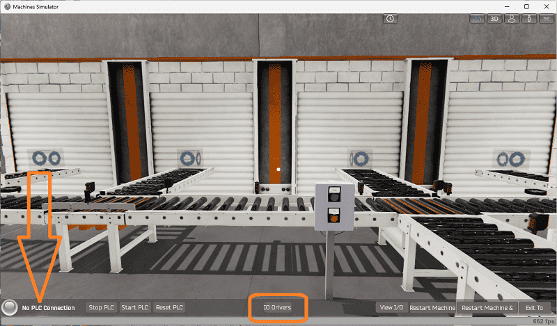
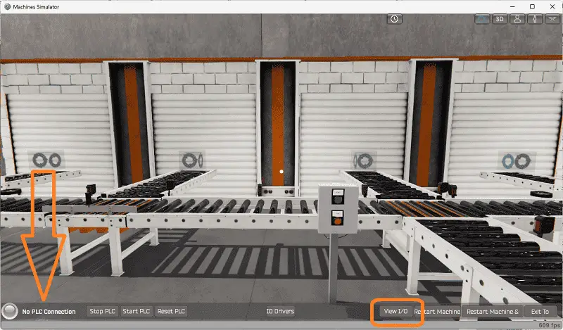
The status of the machine simulator will be at the bottom of the screen. Currently, we have no PLC connected. Select IO Drivers on the bottom middle of the screen.
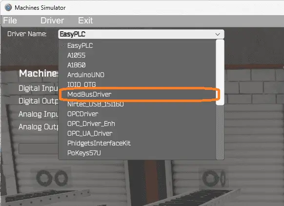
The EasyPLC driver is selected by default. Under the driver pull-down menu, select “ModBusDriver.” This driver will communicate Modbus TCP (Ethernet) and Modbus RTU (Serial).
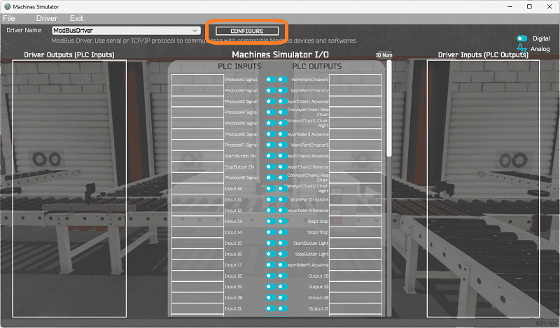
Select the configure button.
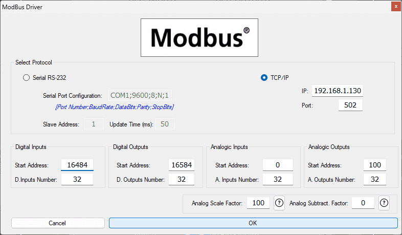
We can now enter the information for our Modbus driver. Select TCP/IP. This means the Ethernet port on the computer will communicate with the PLC.
The digital inputs from MS to the Click PLC will be C101 to C118. This will start at address 16484 due to the offset of 1. Digital outputs from MS to the Click PLC will be C201 to C210. This will begin at address 16494 due to the offset of 1. We are indicating 32 digital inputs and outputs. This is fine because it is more than our EasyPLC machine simulator will require.
We do not use analog inputs or outputs for this PLC programming example.
Select the OK button.
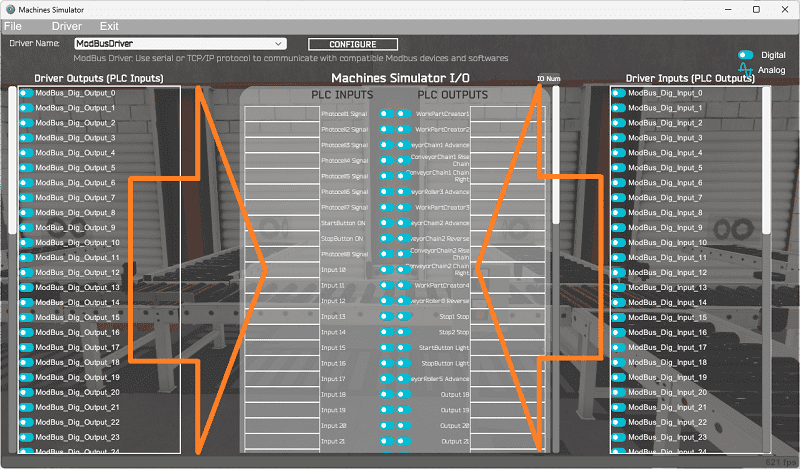
You will now see the inputs and outputs specified for the Modbus driver. We can manually assign the driver outputs to the PLC inputs and the driver inputs to the PLC outputs. However, the automatic assignment works well and will save you time.
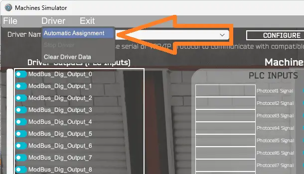
Select Automatic Assignment from the driver option in the main menu.
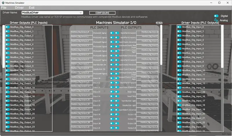
This will automatically assign the PLC IO to the Machine Simulator IO.
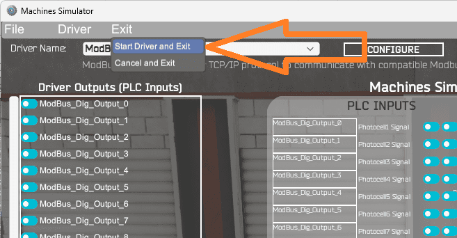
Select start driver and exit from the main menu.
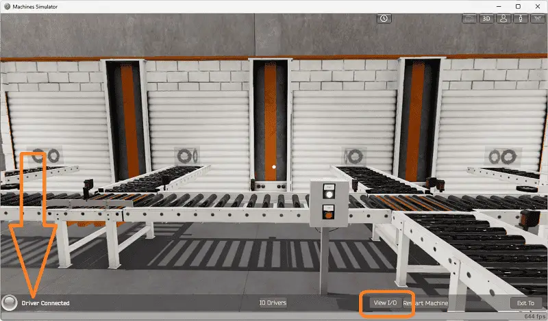
On the bottom left side of the window, you will see that the driver communicates to the PLC with the green light. Select view IO to know the input and output status of the machine simulator.
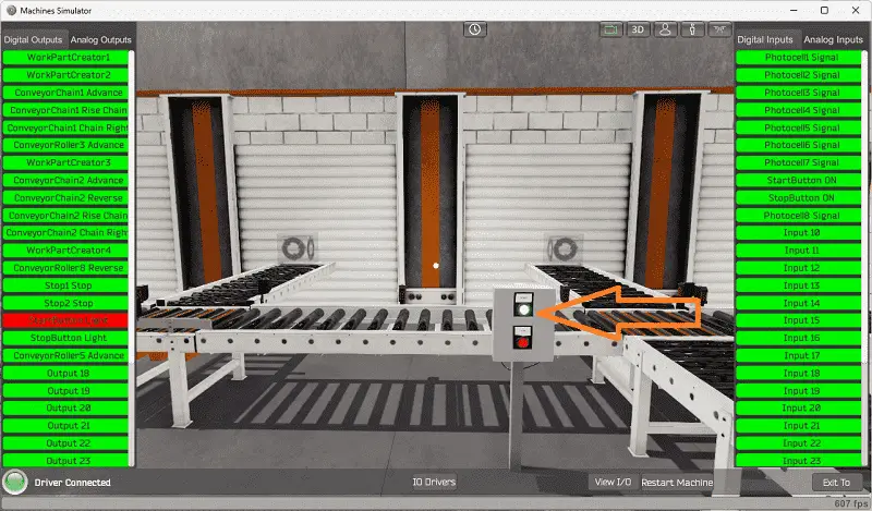
We can now test and operate our EasyPLC multi-feed conveyor machine. Ensure that the PLC is in run mode. Select the flashing green light to start the operation.
Move around this virtual environment while you are testing the program.
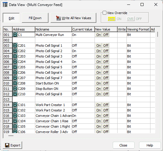
Using the Data View window of the Click PLC programming software, we can also watch the inputs and outputs operate.
Watch the video below to see this operation.
If your program works correctly, it’s time to move on. If not, you’ll need to debug. Monitoring and viewing what is happening in the logic are critical. Looking back on the programming steps, you might have to change your logical sequence and program and test again. This is just part of the process.
When using EasyPLC, debugging is quickly done without damaging any equipment. You may modify your logic several times before you get everything right! To learn more about developing logic, check out our tutorials on the five steps to PLC program development.
You can practice your modification and debug by modifying the multi-feed conveyor operation in the following way:
– Add photocell sensor 7 into the logic for the chain 1 conveyor
– Calculate the skid rate on the exit conveyor in skids per minute
– The line will stop sending skids if you remove one of the boxes before a chain conveyor. Modify the program so that this will not stop if a box is removed anywhere.
Let me know how you make out in the comments below.
Download the Click PLC sample program here.
Watch the video below to see the five steps of program development applied to the sorting operations machine. The machine simulator is one of the best applications to help you learn PLC programming.
EasyPLC Software Suite is a complete PLC, HMI, and Machine Simulator package. This PLC learning package includes the following:
Easy PLC – PLC Simulation allows programming in Ladder, Grafcet, Logic Blocks, or Script.
HMI System – Easily create a visual human-machine interface (HMI)
Machine Simulator – A virtual 3D world with real-time graphics and physical properties. PLC programs can be tested using EasyPLC or through other interfaces. (Modbus RTU, TCP, etc.)
Machine Simulator Lite – Designed to run on Android Devices.
Machine Simulator VR – Virtual Reality comes to life so you can test, train or practice your PLC programming.
Purchase your copy of this learning package for less than USD 75 for a single computer install or less than USD 100 to allow different computers.
Receive 10% off the price by typing in ACC in the comment section when you order. http://www.nirtec.com/index.php/purchase-price/
Learn PLC programming the easy way. Invest in yourself today.
Watch on YouTube: PLC Multi Conveyor Feed Control Demystified!
If you have any questions or need further information, please contact me.
Thank you,
Garry
If you’re like most of my readers, you’re committed to learning about technology. Numbering systems used in PLCs are not challenging to learn and understand. We will walk through the numbering systems used in PLCs. This includes Bits, decimals, Hexadecimal, ASCII, and Floating points.
To get this free article, subscribe to my free email newsletter.
Use the information to inform other people how numbering systems work. Sign up now.

The ‘Robust Data Logging for Free’ eBook is also available for free download. The link is included when you subscribe to ACC Automation.