Learn how to control a rail conveyor palletizer using a CLICK PLC in 5 easy steps! This tutorial is designed to help you understand the basics of PLC programming and its application in industrial automation. From setting up the PLC to writing the ladder logic program, we’ll cover it all. By the end of this tutorial, you’ll be able to control your rail conveyor palletizer with ease using a CLICK PLC. Whether you’re a student, hobbyist, or industrial automation professional, this information is perfect for anyone looking to learn PLC programming and its applications.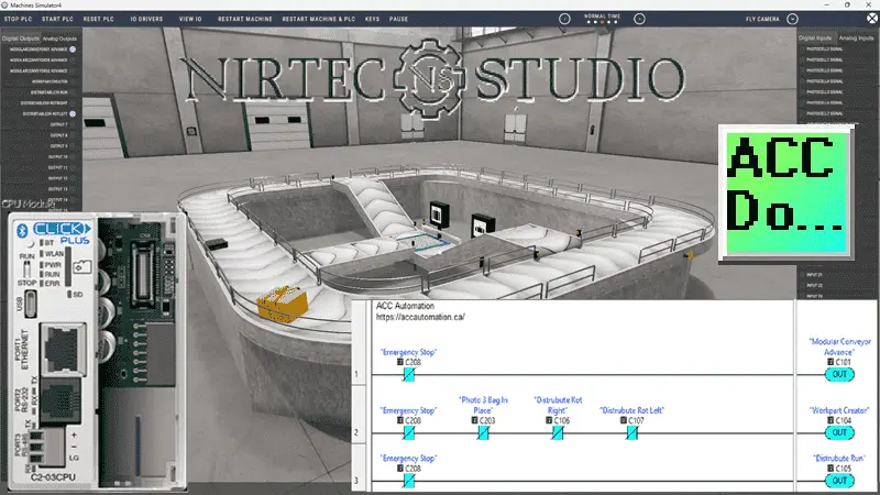
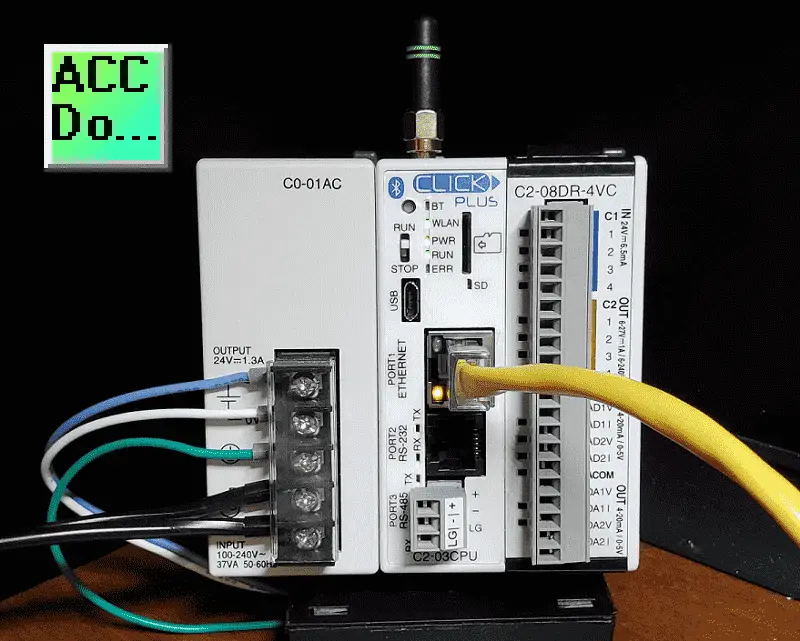
The Rail Conveyor Palletizer is just one of many machines in the Machine Simulator (MS), also known as EasyPLC. The purpose of this system is to control the pallet feeder and the roller table to feed the pallet loading and unloading lines. The Click programming software will be used to program this Click PLUS PLC.
Modbus TCP (Ethernet) will connect the Click to the Machine Simulator (EasyPLC). Discrete and analog inputs and outputs will be controlled from the Machine Simulator (Client) to the Click PLC (Server). We will demonstrate how this rail conveyor palletizer is programmed using the five-step program development process. Let’s get started.
Learn PLC programming the easy way. See below for a 10% discount on this cost-effective learning automation tool. Invest in yourself today.
Previously, we have done the following:
Easy PLC Installing the Software – Video
EasyPLC Software Suite – Quick Start – Video
Click PLC – Easy Transfer Line Programming – Video
Productivity PLC Simulator – Chain Conveyor MS – Video
Do-More PLC – EasyPLC Box Selection Program – Video
Click PLC EasyPLC Gantry Simulator – Video
Click PLC Simple Conveyor EasyPLC – Video
EasyPLC Paint Line Bit Shift – BRX Do-More PLC – Video
Click PLC – EasyPLC PLC Mixer Programming – Video
Click PLC EasyPLC Warehouse Stacker Example – Video
– Operation Video
EasyPLC Machine Simulator Productivity PLC Robotic Cell – Video
EasyPLC Simulator Robotic Cell Click PLC – Video
Palletizing Conveyor Programming Do-More PLC – Video
Palletizing Conveyor Programming – Click PLC – Video
Product Quality Verification! Do-More PLC Sequencer – Video
Revolutionize Learning PLCs with Pallet 3D Sim! – Video
Robot Packing PLC Program Development – Video
Box Dumper Easily Learn PLC Programming – Video
Innovative Solution for Mixing Ink and Bottling – Video
Benchwork 1 Do-More Practice PLC Programming – Video
LS Electric XGB PLC Easy Transfer Program – Video
Do-More PLC Automatic Robot Packing Machine – Video
Latest Machine Simulator Modbus Server Driver – Video
Machine Simulator Modbus Server to C-More HMI – Video
Creating the Ultimate Automation Training Setup
– Part 1 – Video
– Part 2 – Video
Unlock Click PLC & Machine Simulator Integration – Video
Master the Pneumatic Pusher Simulator Now! – Video
Easy Steps to Program a Click PLC Sorting System – Video
Automate Airport Baggage Claim -PLC Programming! – Video
Troubleshoot Baggage Claim – Sensor, PLC Tweaks! – Video
Define the task: (Step 1 – Click PLC Rail Conveyor Palletizer)
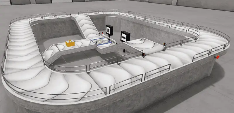
The first step in developing a Click or any PLC program is determining what must be done. Start the Machine Simulator (MS). Select the machine’s button on the main page or select machines from the main menu at the machine simulator window.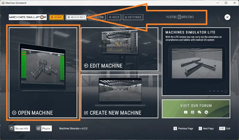
All available pre-built machines for practicing PLC programming will now be displayed.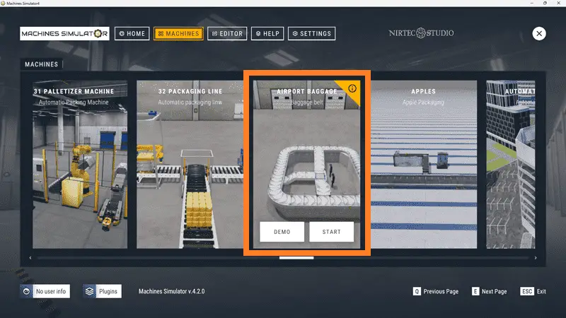
Move your mouse over the “33 Rail Conveyor Palletizer” machine. This is the machine that we will be programming. Three items will be displayed. Click the information button on the top right of the screen.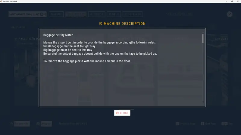
This will show you a description of the rail conveyor palletizer. Select Close.
The rail conveyor palletizer simulator has a demo mode. This will allow you to observe the machine’s operation, enabling us to understand the basics of how it functions. Select the demo mode for the rail conveyor station.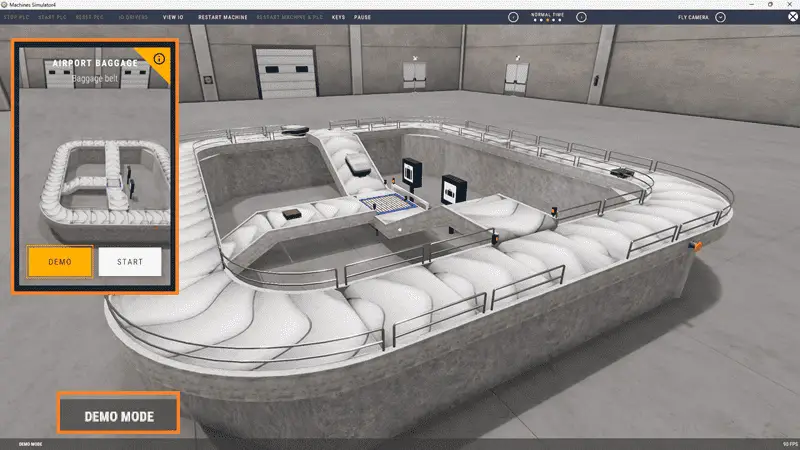
The demonstration mode will only show you the operation.
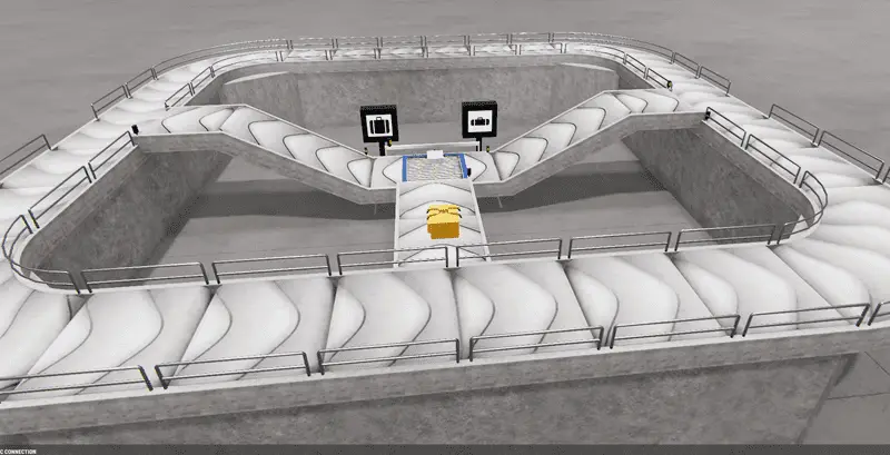
The purpose of this system is to control the pallet feeder and roller table, enabling the pallet loading and unloading lines to operate efficiently.
The robot operates autonomously, and its operation does not require programming.
The PLC must manage the pallet feeder to load groups of 6 pallets for dosing. Once the 6 pallets are unloaded, another 6 pallets must be loaded to distribute them to the feeding system.
The conveyor roller table must leave the pallet on the first line so that the robot can load it with a box. Once loaded, it must be taken by the rail system to the unloading line to remove the pallet with the loading box. Additionally, the camera system detects two types of boxes; each type must be removed from a different exit line.
Move around the 3D virtual environment.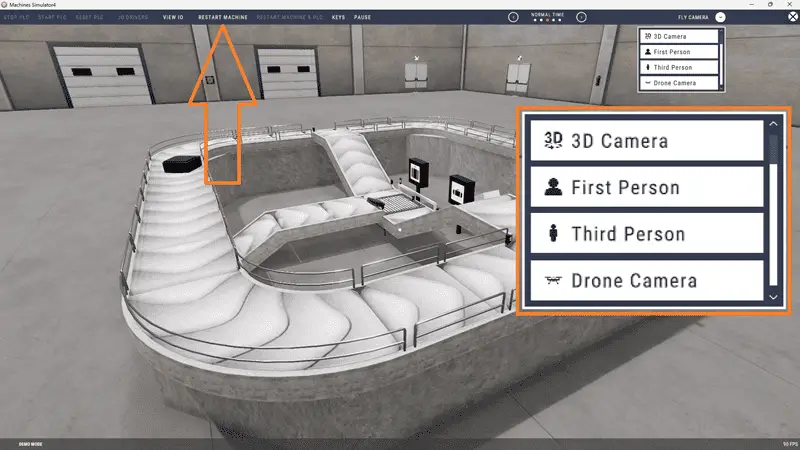
The icons at the top of the window enable you to navigate this 3D environment. The first icon is the default selection. This will allow you to move around without bumping into the components. The last icon will automatically show you around this virtual environment. The first-person mode will mimic a person in your 3D learning world. The third person will show you an operator and their relationship to the bagging belt machine. Once we understand what needs to be done, we can proceed to the next step in developing the Click PLC program.
Watch the video below for a sequence of operations.
Define the Inputs and Outputs: (Step 2 – Click PLC Rail Conveyor Palletizer)
At the top of the rail conveyor palletizer simulator window, the View I/O will display the inputs and outputs required for this example. The outputs are on the left-hand side, and the inputs are on the right-hand side.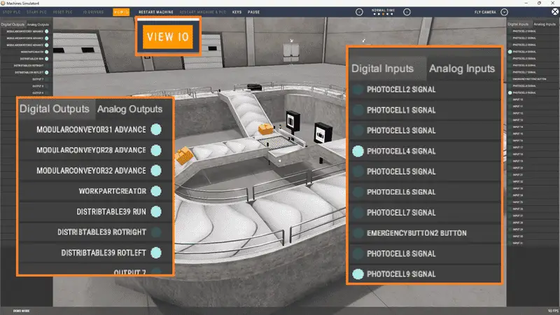
While still in demo mode, you can see the operation of the inputs and outputs.
The rail conveyor palletizer will require 23 digital outputs and 24 digital inputs. It will also need one analog input for the camera output. This identifies the box type. If you are unsure what the output or input is doing, start the rail conveyor palletizer in Start mode.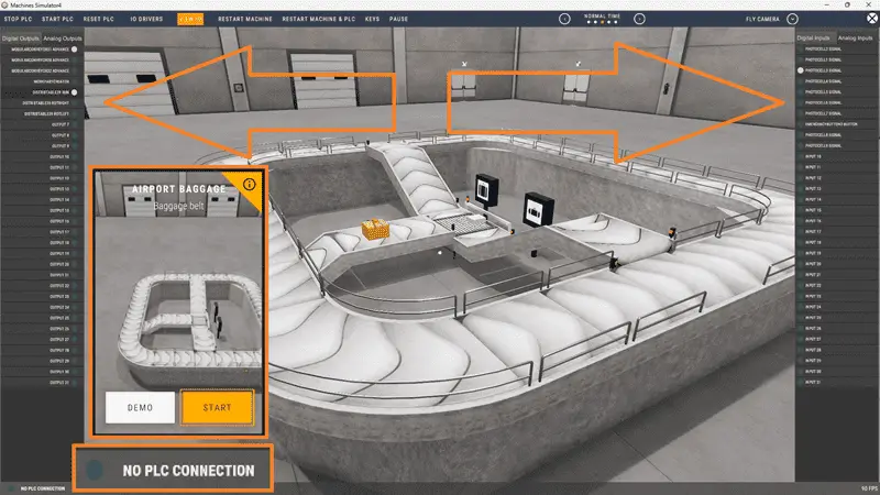
Select View IO at the top middle of the rail conveyor palletizer simulator window. We can manually operate the rail conveyor palletizer without a control system, such as a Click PLC.
Clicking on the outputs will allow you to turn them on manually. You can then monitor the inputs to see their operation. The restart button at the top of the machine simulator window resets the scene to its starting point. The following table defines the inputs and outputs (I/O) and Modbus addresses we will use in the Click PLC for this program.
| Digital Type | Description | Click PLC Modbus Address | Machine Simulator Modbus Address |
| PLC Output – MS Input | Pallet Stacker Move DWN | 16485 – C101 | 16484 |
| PLC Output – MS Input | Pallet Stacker Move UP | 16486 – C102 | 16485 |
| PLC Output – MS Input | Pallet Stacker Move 2ND | 16487 – C103 | 16486 |
| PLC Output – MS Input | Pallet Stacker GRIP | 16488 – C104 | 16487 |
| PLC Output – MS Input | Table Rollers ADV | 16489 – C105 | 16488 |
| PLC Output – MS Input | Table Rollers REV | 16490 – C106 | 16489 |
| PLC Output – MS Input | Create Pallets | 16491 – C107 | 16490 |
| PLC Output – MS Input | Output 7 | 16492 – C108 | 16491 |
| PLC Output – MS Input | Convey 1 ADV | 16493 – C109 | 16492 |
| PLC Output – MS Input | Work Part Creator6 | 16494 – C110 | 16493 |
| PLC Output – MS Input | CBELT_L1 ADV | 16495 – C111 | 16494 |
| PLC Output – MS Input | CBELT_L1 REV | 16496 – C112 | 16495 |
| PLC Output – MS Input | Output 12 | 16497 – C113 | 16496 |
| PLC Output – MS Input | Roller Loading Boxes | 16498 – C114 | 16497 |
| PLC Output – MS Input | CBELT_02 ADV | 16499 – C115 | 16498 |
| PLC Output – MS Input | PickerRobot Pick | 16500 – C116 | 16499 |
| PLC Output – MS Input | Table Roller to Unload | 16501 – C117 | 16500 |
| PLC Output – MS Input | Table Roller to Load | 16502 – C118 | 16501 |
| PLC Output – MS Input | Beacon Light 1 | 16503 – C119 | 16502 |
| PLC Output – MS Input | Beacon Light 2 | 16504 – C120 | 16503 |
| PLC Output – MS Input | ECabinet Green LED | 16505 – C121 | 16504 |
| PLC Output – MS Input | CBELT_04 ADV | 16506 – C122 | 16505 |
| PLC Output – MS Input | Camera 1 Start | 16507 – C123 | 16506 |
| PLC Input – MS Output | Pallet Stacker1 UP | 16585 – C201 | 16584 |
| PLC Input – MS Output | Pallet Stacker1 DWN | 16586 – C202 | 16585 |
| PLC Input – MS Output | Pallet Stacker1 SecPos | 16587 – C203 | 16586 |
| PLC Input – MS Output | Pallet Stacker1 Cyls ADV | 16588 – C204 | 16587 |
| PLC Input – MS Output | Pallet Stacker1 Cyls BCK | 16589 – C205 | 16588 |
| PLC Input – MS Output | Photocell1 Signal | 16590 – C206 | 16589 |
| PLC Input – MS Output | PHC2 Signal | 16591 – C207 | 16590 |
| PLC Input – MS Output | PHC1 Signal | 16592 – C208 | 16591 |
| PLC Input – MS Output | PHL1 Signal | 16593 – C209 | 16592 |
| PLC Input – MS Output | Machine Door 1 Opened | 16594 – C210 | 16593 |
| PLC Input – MS Output | Machine Door 2 Opened | 16585 – C201 | 16584 |
| PLC Input – MS Output | PHL2 Signal | 16586 – C202 | 16585 |
| PLC Input – MS Output | PHL3 Signal | 16587 – C203 | 16586 |
| PLC Input – MS Output | PickerRobot Detect | 16588 – C204 | 16587 |
| PLC Input – MS Output | Table Stopped | 16589 – C205 | 16588 |
| PLC Input – MS Output | ECabinet Green Button | 16590 – C206 | 16589 |
| PLC Input – MS Output | ECabinet Red Button | 16591 – C207 | 16590 |
| PLC Input – MS Output | ECabinet Yellow Button | 16592 – C208 | 16591 |
| PLC Input – MS Output | ECabinet Emergency | 16593 – C209 | 16592 |
| PLC Input – MS Output | PHL1 Box Signal | 16594 – C210 | 16593 |
| PLC Input – MS Output | Input 20 | 16590 – C206 | 16589 |
| PLC Input – MS Output | ECabinet Sel Positon 1 | 16591 – C207 | 16590 |
| PLC Input – MS Output | ECabinet Sel Positon 2 | 16592 – C208 | 16591 |
| PLC Input – MS Output | Camera 1 END | 16593 – C209 | 16592 |
| PLC Input – MS Output | PHL4 Signal | 16594 – C210 | 16593 |
| Analog PLC Input – MS Output | Camera 1 Result | 40101 – DS101 | 100 |
Note: The machine simulator will be offset by one on the Modbus Addresses.
We can use the Click PLC Software to view the address picker and determine the Modbus addresses required for the program.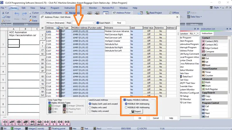
Develop a logical sequence of operation: (Step 3 – Click PLC Rail Conveyor Palletizer)
A flow chart or sequence table is used to understand the process that needs to be controlled thoroughly. It must also answer questions like the following:
What happens when electrical power and pneumatic air are lost?
What happens when the input/output devices fail?
Do we need redundancy?
This step allows you to save yourself a lot of work by understanding everything about the operation. It will help prevent you from continually rewriting the PLC program logic. Knowing all of these answers upfront is vital in developing the PLC program.
The emergency stop button will start and stop our airport baggage claim station. The top, main conveyor will always be running, moving the bags around for passengers to select their luggage. If no bags are sensed with photoelectric sensors 1 and 3, a workpart output will be energized. This will create a bag and move it to the distribution table. When photo 2 senses the bag, the distribution run output will be on, as the bag moves toward photo 3.
If photos 3 and 1 are on, this is a large bag. The distribution run left will turn on, sending the bag to the left. When photo 9 sees the bag, the left conveyor turns on, sending it up until it sees photo 5. If photo 7 or a time delay is not on, then the bag will enter the top, main conveyor.
This is a small bag if photos 3 and not 1 are on. The distribution run to the right will turn on, sending the bag to the right. When photo 8 sees the bag, the right conveyor turns on, sending it up until it sees photo 4. If photo 6 or a time delay is not on, then the bag will enter the top, main conveyor.
Creating the sequence of operations is the hardest part of the programming development process. Getting all of the conditions down for each output based on the inputs is critical. Let me know if you agree in the comments below.
A PLC programmer must know everything about the sequence and operation of the machine before programming.
Did you know that an estimated 64 million bags are mishandled each year at airports? Imagine the chaos that could be avoided with automation! Ask questions or review existing documentation to ensure you understand the logical steps involved in the machine’s operation.
Develop the PLC program: (Step 4 – Click PLC Rail Conveyor Palletizer)
Writing the ladder logic code for our Click PLC baggage belt station example will be the next step in our program development.
We will use the Click PLC programming software and a Click PLUS CPU. Call up the Address Picker from the Home tab. Select the display MODBUS option to see the addresses used for our communication.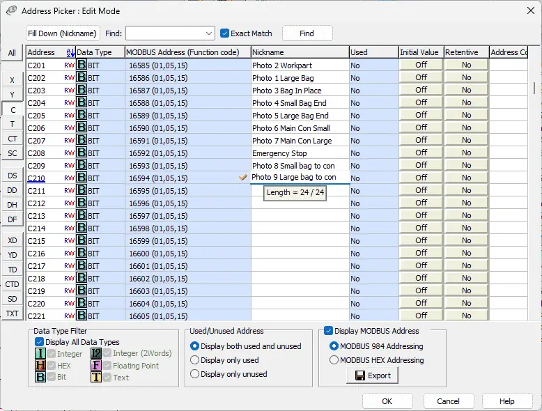
We can now enter the names for our inputs and outputs from the machine simulator for our airport baggage claim machine.
Detailed information on the Click PLC can be found in our Click PLC Series. Our program will be written using ladder logic. (Ladder Diagram)
Do not worry that we do not document all of the names in our program. This can be added later as we need further variables in our program. Save and transfer our program to the Click PLC. It is good practice to save often during programming. This can save you a lot of time if the unexpected happens, such as a computer crash or a power outage.
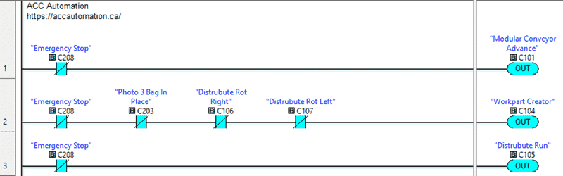
We will first program the top main conveyor. The modular conveyor advance will be on when the emergency stop is not activated.
The emergency button input will be a condition to run any rung of our ladder logic program. When we do not have the photo 3 bag in place and it is not rotating left or right on the distribution table, the workplart creator will be activated. This will create the next bag to be placed on our airport baggage claim.
Our distributed run output will always be on when the emergency stop is not activated.
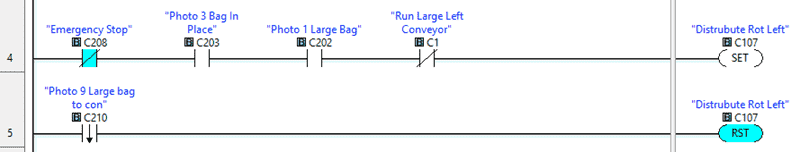
When a bag is in place with photo 3 and photo 1, it indicates a large bag, and we are not running the left conveyor to bring it to the main conveyor, then set the distribute run left output. This distributed run left will be reset on the trailing edge of the photo 9 large bag sensor.
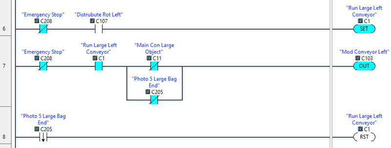
When the Distribute Rotates Left output is on, we will set an internal bit C1 to run the conveyor to the main. If the internal bit is on and we do not have objects in the way to move the bag to the main conveyor or not the large bag photo 5 end sensor, then the Modular Conveyor Left will be on. Our internal C1 bit will be reset on the trailing edge of photo 5. This is when the bag leaves the conveyor and rotates on the main one.
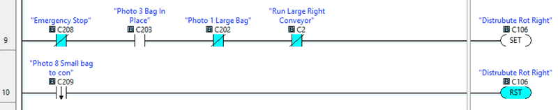
When a bag is in place with photo 3 and not photo 1, it indicates a small bag, and we are not running the right conveyor to bring it to the main conveyor, then set the distribution run right output. This distributed run right will be reset on the trailing edge of the photo 8 small bag sensor.
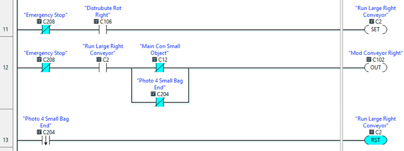
When the Distribute Rotates Right output is on, we will set an internal bit C2 to run the conveyor to the main. If the internal bit is on and we do not have objects in the way to move the bag to the main conveyor or not the small bag photo 4 end sensor, then the Modular Conveyor Right will be on. Our internal C2 bit will be reset on the trailing edge of photo 4. This is when the bag leaves the conveyor and rotates on the main one.
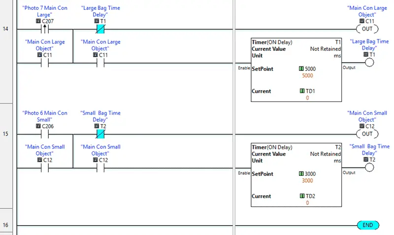
The ladder logic rung program for the objects in the way, on the main conveyor, is similar. On the leading edge of photo 7, and not the time delay, we will set the internal bit C11 on to indicate objects are in the way, so no bags must be moved to the main conveyor. This is for the large bags being moved to the main conveyor.
The leading edge one-shot is used because the photo 7 sensor must be moved to allow the program to work correctly. You will notice that the conveyor movement of the large bag will sometimes trigger the photo 7 sensor before it gets onto the main conveyor.
When photo 6, and not the time delay, we will set the internal bit C12 on to indicate objects are in the way, so no bags must be moved to the main conveyor. This is for the small bags being moved to the main conveyor.
Save and download the PLC program.
Our program is now complete.
You can download this program below.
We communicate with the machine simulator using Modbus TCP (Ethernet or Wireless). The ports will be set up with a fixed IP address so the machine simulator (Modbus Client) can find the Modbus Server.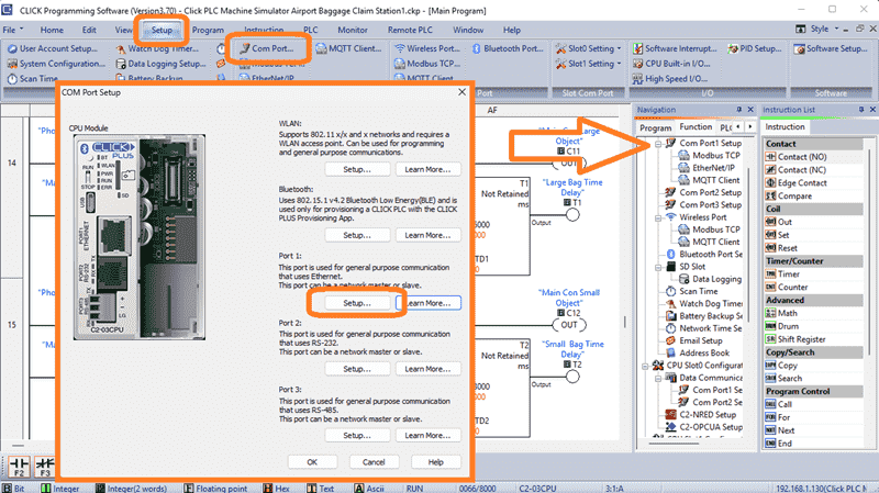
Select Modbus TCP from the communication port on the Function tab of the navigation window. You can also use the main menu | Setup | Com Port…
The COM port setup window will now be displayed. Click on the Setup Button for Port 1.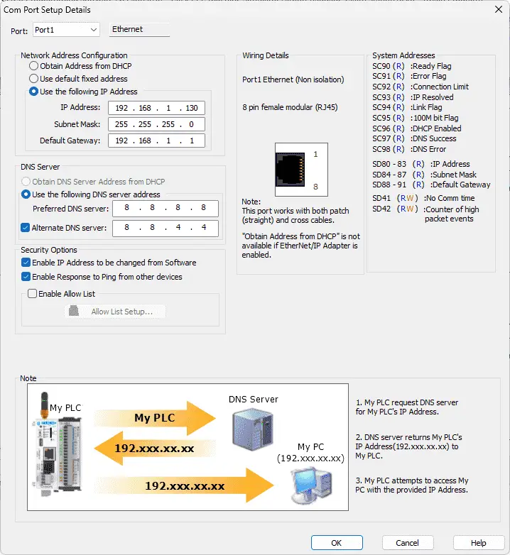
You can now set the static IP address on the Com Port Setup Details window. Make a note of the IP address. We will need this to connect to our Machine Simulator.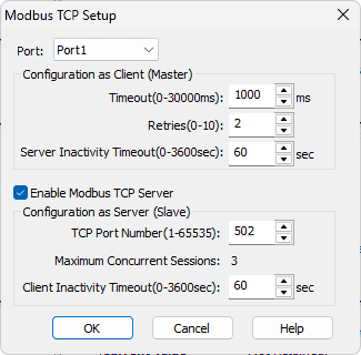
Select Modbus TCP Setup from the main menu | Setup. Ensure the “Enable Modbus TCP Server” is checked for our port.
Ensure that the PLC is in run mode. Select “Status” to see the active status of the inputs and outputs on the ladder logic.
Test the program: (Step 5 – Click PLC Rail Conveyor Palletizer)
We will use Modbus TCP on our Click PLUS PLC to communicate with the EasyPLC Machine Simulator. Call up the Airport Baggage Claim in start mode.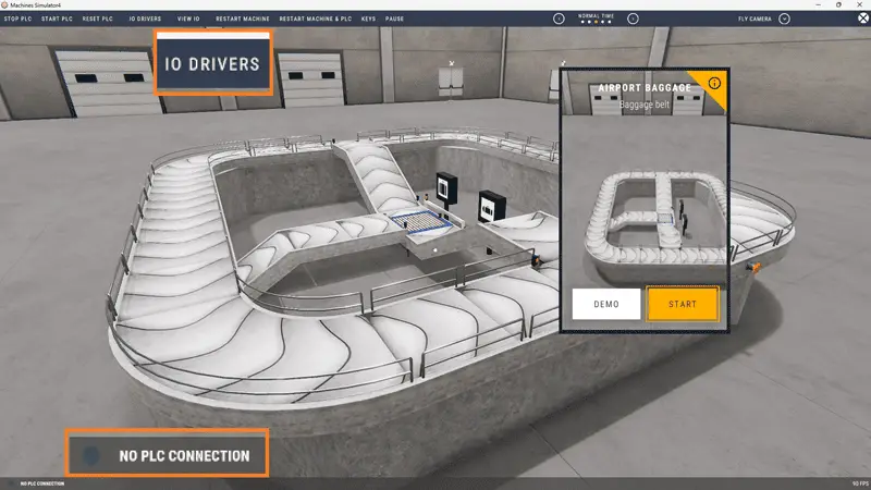
The status of the machine simulator will be at the bottom left of the screen. Currently, we have no PLC connected. Select IO Drivers at the top of the screen.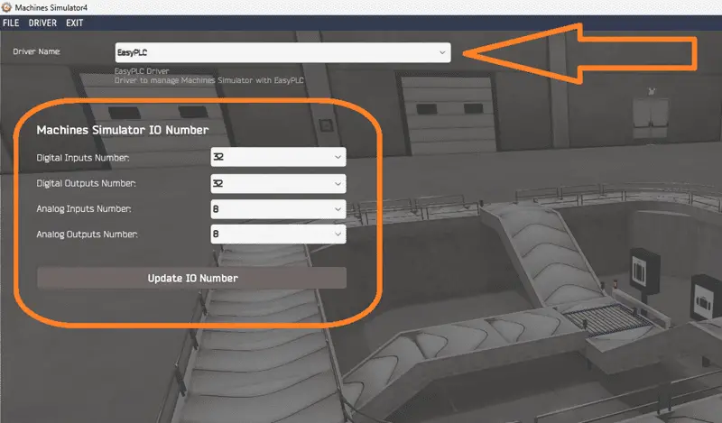
The machine simulator IO number will be displayed. Ensure we select more IO than required for our baggage belt machine. The EasyPLC driver is selected by default.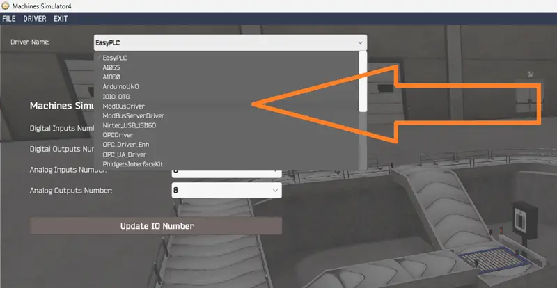
Under the driver pull-down menu, select “ModbusDriver.” This driver supports Modbus TCP (Ethernet) and Modbus RTU (Serial) protocols. Select the down arrow on the driver’s name.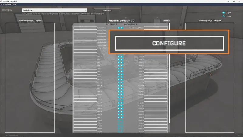
Select the configure button.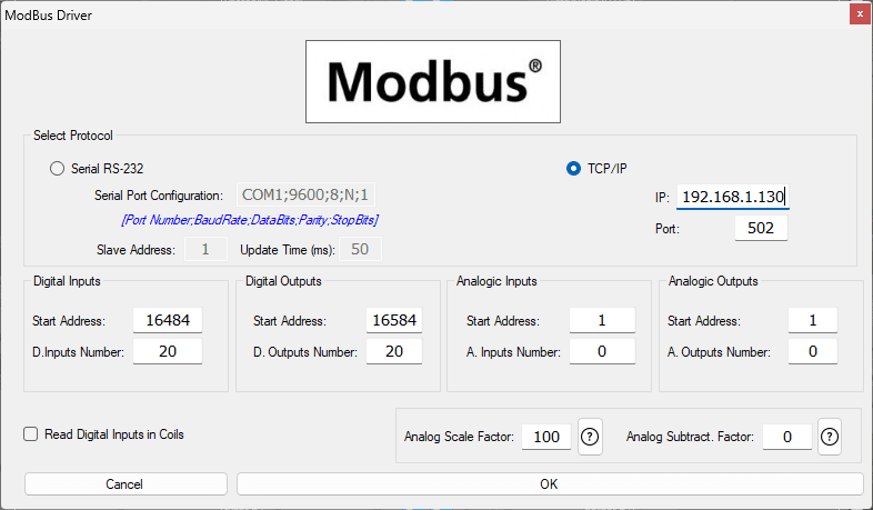
We can now enter the information for our Modbus driver. Select TCP/IP. This means the Ethernet port on the computer will communicate with the Click PLC. The digital inputs from MS to the Click PLC will be C101 to C107. This will start at address 16484 due to the offset of 1. Digital outputs from MS to the Click PLC will be C201 to C210. This will begin at address 16584 due to the offset of 1. Select the OK button.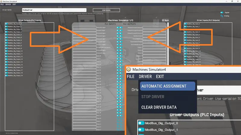
You will now see the inputs and outputs specified for the Modbus driver. We can now manually assign the driver outputs to the PLC inputs and the driver inputs to the PLC outputs. However, the automatic assignment works well and will save you time.
Select Automatic Assignment from the driver option in the main menu.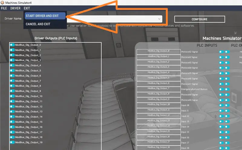
This will automatically assign the PLC IO to the Machine Simulator IO. Select Start Driver and exit from the main menu.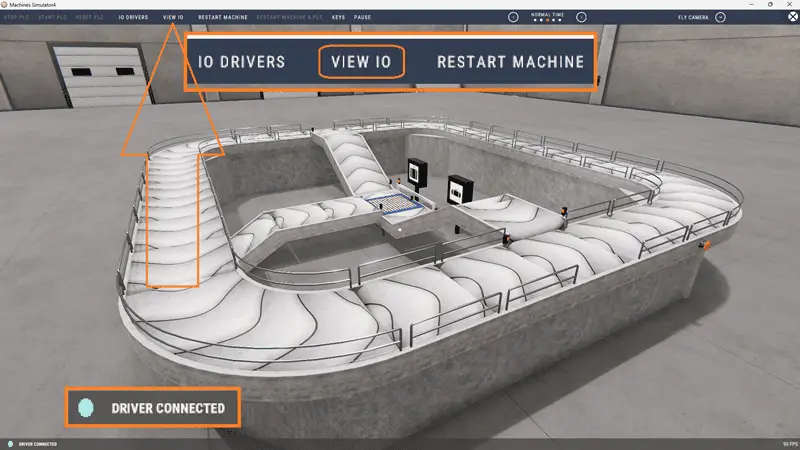
On the bottom left side of the window, the driver communicates with the Click PLUS PLC.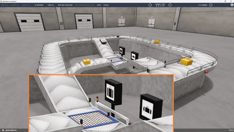
Ensure that the Click PLC is in run mode. We can see the operation of our baggage belt machine. Test the machine to see if errors occur.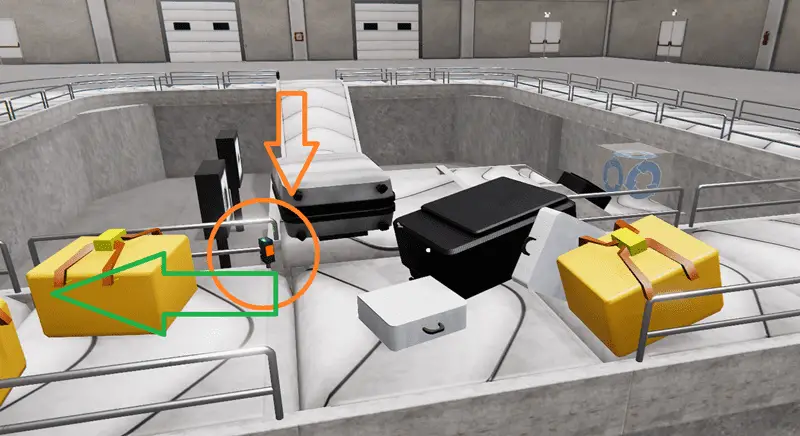
We know from our sequence of operation that the sensor entry to the main conveyor for the large bag will falsely trigger on some of the bags. Mechanically, this must be moved. Our program used the one-shot to compensate for the sensor location.
Select View IO to know the input and output status of the machine simulator.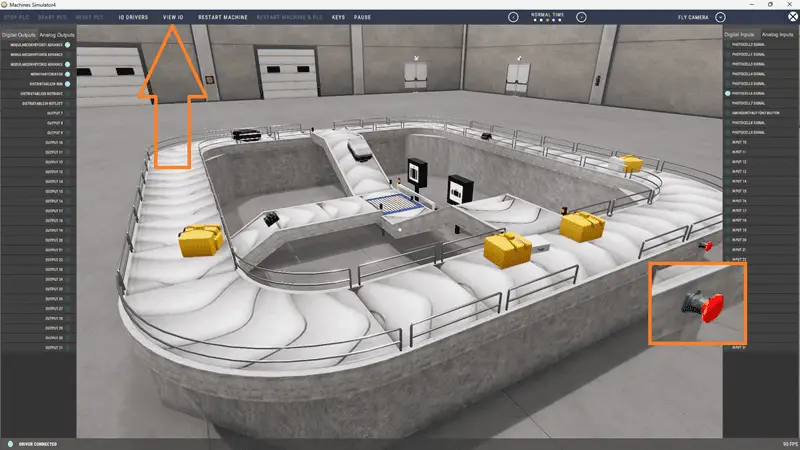
The digital inputs and outputs of the MS will correspond to the PLC controller.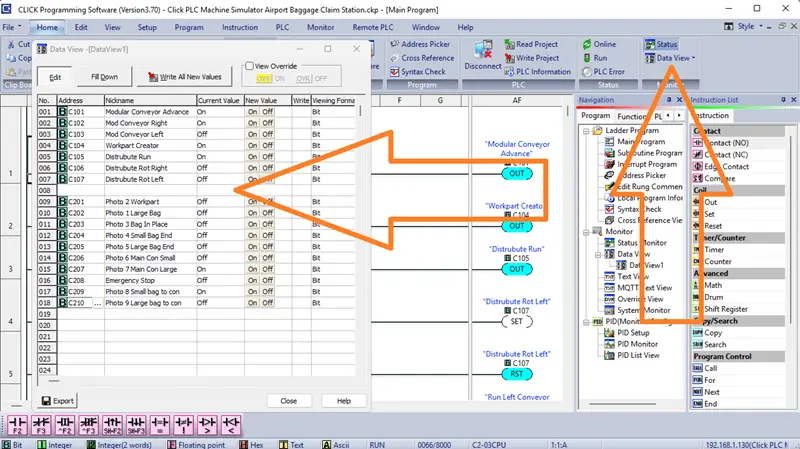
Using the Data View window of the Click programming software, we can also watch the input and output operations.
Using a Machine Simulator (MS) to test the program will ensure that our program works. Troubleshooting is quickly done without damage to any physical hardware.
You can practice your modification and debugging by modifying the sorting station operation in the following way:
– Move the photo before the large bag opening to eliminate false triggering. You will also have to modify the one-shot in the program.
– Add a counter for each of the sorted bags. The counter will show the number of large and small bags on the appropriate exit conveyor. Add a reset to zero these counters.
– Calculate the rate of bags per hour. This can be calculated using the PLC ladder logic and indicate when we need additional airport baggage claim machines.
Let me know how you make out in the comments below.
Download the Click PLC sample program here.
Watch the video below to see the five steps of program development applied to the sorting station machine. The machine simulator is one of the best applications to help you learn PLC programming.
The sorting station box selection (camera management and distribution) is just one of many machines in the EasyPLC Machine Simulator (MS). This sorting station will read barcodes from the boxes and send them to different exit ramps. The Click programming software will be used to program this Click PLUS PLC.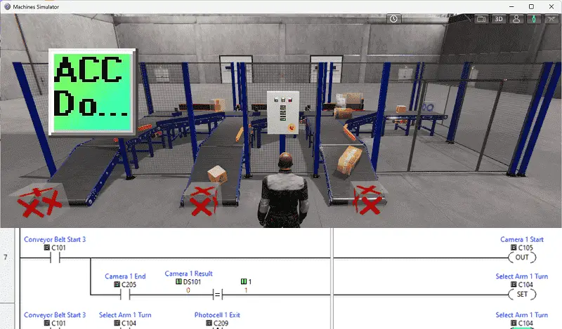
Modbus TCP (Ethernet) will connect the Click to the EasyPLC Simulator. Discrete inputs, outputs, and registers will be controlled from the EasyPLC Simulator (Client) to the Click PLC (Server). Using the five steps for program development, we will show how this sorting station is programmed. Let’s get started.
Learn PLC programming the easy way. See below for a 10% discount on this cost-effective learning tool. Invest in yourself today.
The entire series can be found here.
Here are some previous posts we have done:
Easy PLC Installing the Software – Video
EasyPLC Software Suite – Quick Start – Video
Click PLC – Easy Transfer Line Programming – Video
Productivity PLC Simulator – Chain Conveyor MS – Video
Do-More PLC – EasyPLC Box Selection Program – Video
Click PLC EasyPLC Gantry Simulator – Video
Click PLC Simple Conveyor EasyPLC – Video
EasyPLC Paint Line Bit Shift – BRX Do-More PLC – Video
Click PLC – EasyPLC PLC Mixer Programming – Video
Click PLC EasyPLC Warehouse Stacker Example – Video
– Operation Video
EasyPLC Machine Simulator Productivity PLC Robotic Cell – Video
EasyPLC Simulator Robotic Cell Click PLC – Video
EasyPLC Simulator Robotic Cell BRX Do-More PLC – Video
– EasyPLC Factory Editor Robotic Cell Additions Video
4 Way Traffic Light PLC Program EasyPLC – Video
Rock Crusher Plant EasyPLC BRX Do-More – Video
Freight Carrier Weighing and Distribution EasyPLC – Video
EasyPLC Machining Center Loading Robots – Video
EasyPLC Palletizing Robot Programming Click PLC – Video
EasyPLC Machine Editor – Design a Simulation – Video
PLC Programming Mixing Tank – EasyPLC / Do-More – Video
EasyPLC Solder Robot PLC Programming – Video
PLC Programming – A Tutorial for Beginners – Video
Automated Parking Demo Video
Parking Cars Simulator PLC Programming Part 1 – Video
Parking Cars Simulator PLC Programming Part 2 – Video
PLC Programming with Pneumatic Synchronization – Video
The Ultimate Guide to PLC Programming for Sorting Operations – Video
Optimizing Batch Processing with PLC Systems – Video
PLC Multi Conveyor Feed Control Demystified! – Video
PLC Program Sequence for Efficient Robot Loading – Video
Streamline Programming Do-More EasyPLC Transfer – Video
Programming Chain Conveyor Transfer with Do-More – Video
Define the task: (Step 1 – Click PLC Sorting Station)
Start the EasyPLC Machine Simulator software. Select the start button on the main screen or select machines from the main menu. All sample programs you can practice your PLC program will be listed.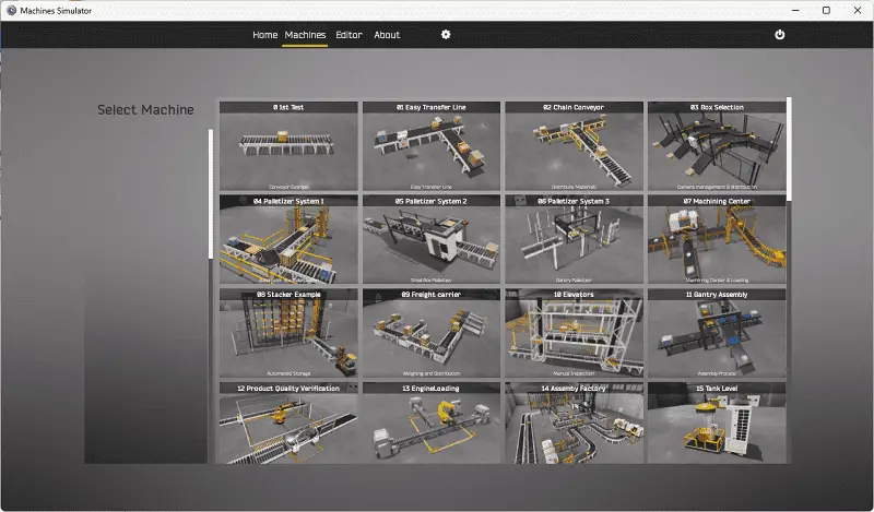
Click on the “03 Box Selection” machine.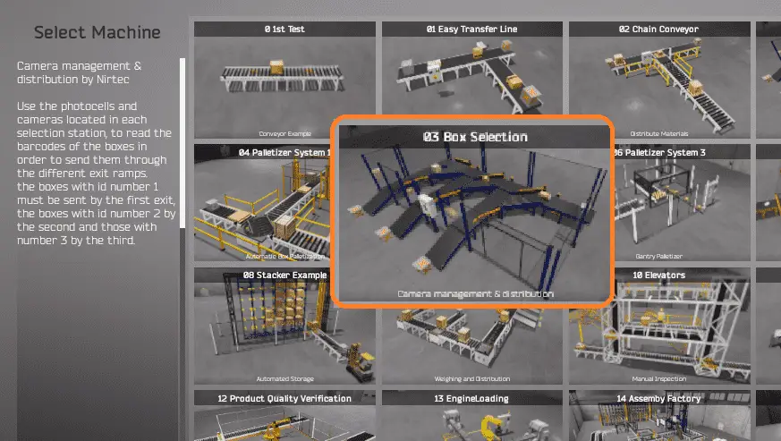
There is also a written version of the sequence on the left-hand side of the machine.
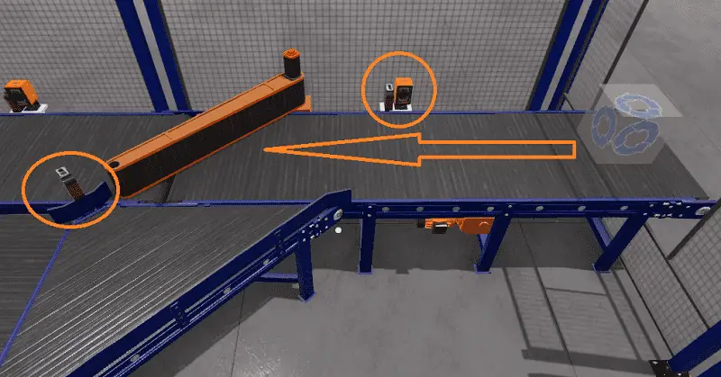
Camera management and distribution (box selection sorting station) will use photocells and cameras. These are located in each selection station and will read the barcodes of the boxes. The box will be sent down the corresponding exit ramp. Box ID 1 will be sent to the first Exit, ID 2 to the second Exit, and ID 3 to the third Exit. The number of boxes sent down each Exit will be displayed on the control panel.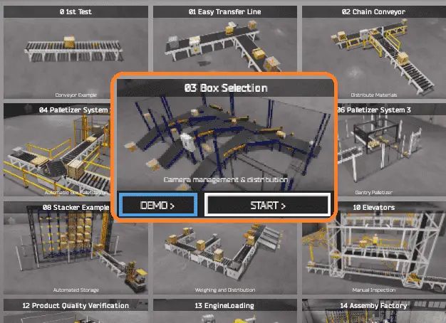
The machine simulator has a demo mode for the built-in machines. Select the demo mode. This will allow you to watch the operation of the box sorting station. This will help you see what has to be done.
Move around the 3D virtual environment. The icons on the top of the window will allow you to move around this 3D environment.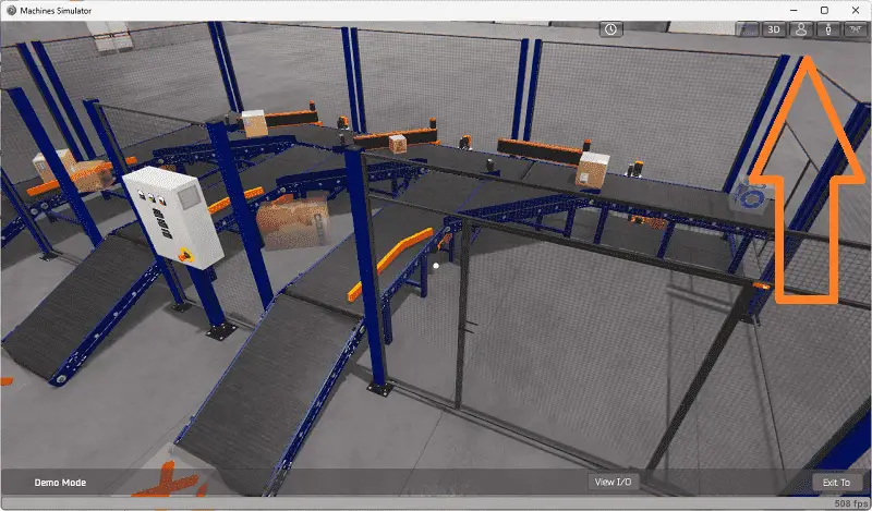
The first icon is the default selection. This will enable you to move around without bumping into the components. The first-person mode will mimic a person in your 3D learning world.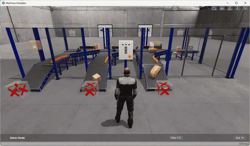
The third person is used to show the operator’s relationship to the machine. The last icon will automatically show you around this virtual environment. Once we understand what must be done, we can move on to the next step in our PLC program development.
Watch the sequence of operation video below.
Define the Inputs and Outputs: (Step 2 – Click PLC Sorting Station)
While still in the demo mode of the machine simulator, we can select the View IO on the bottom menu.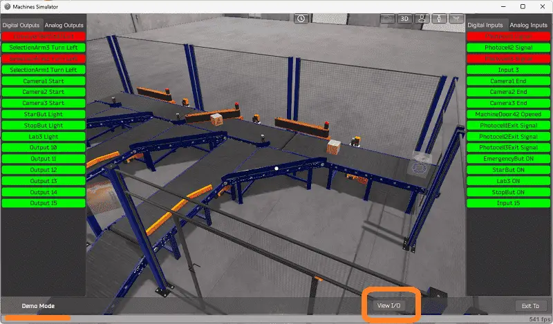
This will now show the digital outputs on the left-hand side of the screen and the digital inputs on the right-hand side of the screen. We can watch how the IO relates to the demo program. Select the exit button to stop the demo mode of the machine simulator.
Start the box selection sorting station in start mode.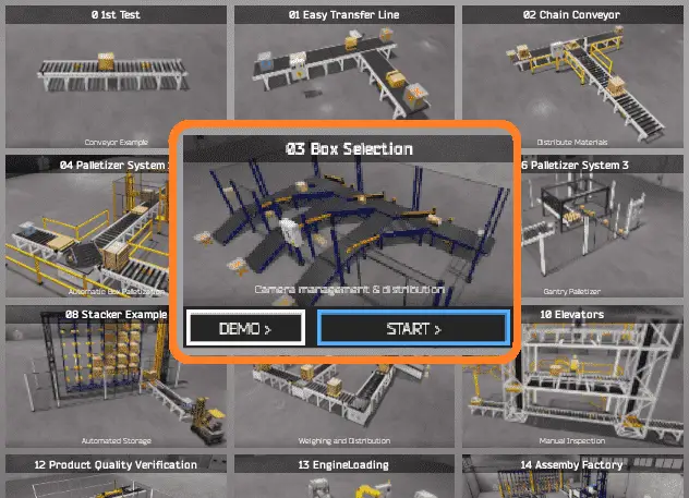
Select the View IO to display the inputs and outputs required for this machine.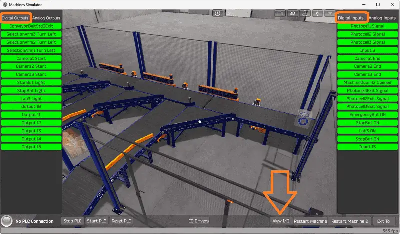
Select the Analog inputs and outputs to view them.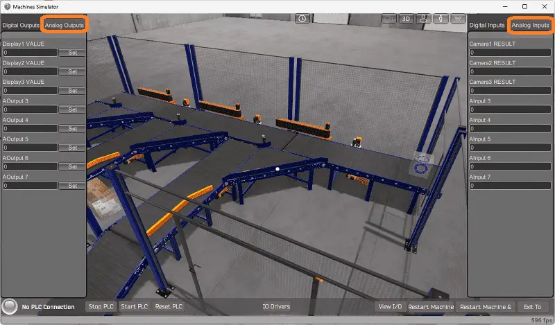
The EasyPLC sorting station box selection machine simulator will require ten digital outputs and 15 digital inputs. It will also need three analogs in and out. The analog outputs are for the exit ramp counts. Analog inputs are for each camera on the exit ramps to read the box barcode.
Clicking on the digital outputs will activate it. Spend some time understanding the IO (inputs and outputs) functions fully.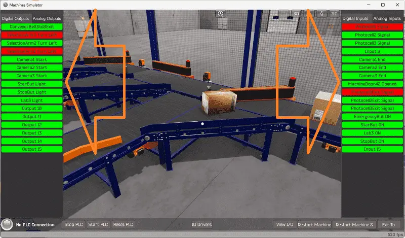
You can move around in the 3D environment and see the IO and items from different angles.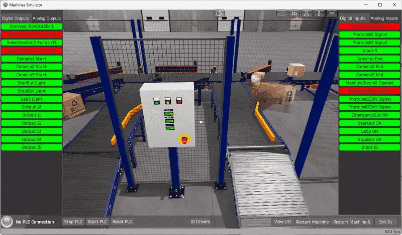
The machine simulator will be communicating to a Click PLC. Communication will be done with Modbus.
We can look at the address picker using the Click PLC Software to determine the Modbus Addresses we require for the program.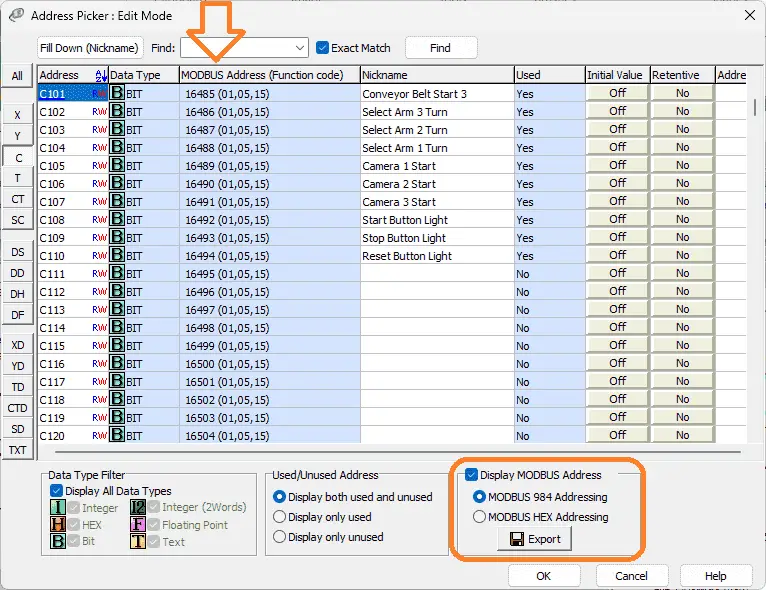
The following table will define the inputs and outputs (IO) and Modbus addresses in the Click PLC we will use for this program.
| Digital Type | Description | Click PLC Modbus Address | Machine Simulator Modbus Address |
| PLC Output – MS Input | Conveyor Belt Start 3 | 16485 – C101 | 16484 |
| PLC Output – MS Input | Select Arm 3 Turn | 16486 – C102 | 16485 |
| PLC Output – MS Input | Select Arm 2 Turn | 16487 – C103 | 16486 |
| PLC Output – MS Input | Select Arm1 Turn | 16488 – C104 | 16487 |
| PLC Output – MS Input | Camera 1 Start | 16489 – C105 | 16488 |
| PLC Output – MS Input | Camera 2 Start | 16490 – C106 | 16489 |
| PLC Output – MS Input | Camera 3 Start | 16491 – C107 | 16490 |
| PLC Output – MS Input | Start Button Light | 16492 – C108 | 16491 |
| PLC Output – MS Input | Stop Button Light | 16493 – C109 | 16492 |
| PLC Output – MS Input | Reset Button Light | 16494 – C110 | 16493 |
| Analog PLC Output – MS Input | Exit 1 Conveyor Count | 40001 – DS1 | 0 |
| Analog PLC Output – MS Input | Exit 2 Conveyor Count | 40003 – DS2 | 1 |
| Analog PLC Output – MS Input | Exit 3 Conveyor Count | 40004 – DS3 | 2 |
| PLC Input – MS Output | PhotoCell 1 Signal | 16585 – C201 | 16584 |
| PLC Input – MS Output | PhotoCell 2 Signal | 16586 – C202 | 16585 |
| PLC Input – MS Output | PhotoCell 3 Signal | 16587 – C203 | 16586 |
| PLC Input – MS Output | Camera 1 End | 16589 – C205 | 16588 |
| PLC Input – MS Output | Camera 2 End | 16590 – C206 | 16589 |
| PLC Input – MS Output | Camera 3 End | 16591 – C207 | 16590 |
| PLC Input – MS Output | Machine Door Open | 16592 – C208 | 16591 |
| PLC Input – MS Output | PhotoCell 1 Exit | 16593 – C209 | 16592 |
| PLC Input – MS Output | PhotoCell 2 Exit | 16594 – C210 | 16593 |
| PLC Input – MS Output | PhotoCell 3 Exit | 16595 – C211 | 16594 |
| PLC Input – MS Output | Emergency Button | 16596 – C212 | 16595 |
| PLC Input – MS Output | Stop Button | 165897- C213 | 16596 |
| PLC Input – MS Output | Reset Button | 16598 – C214 | 16597 |
| PLC Input – MS Output | Start Button | 165899- C215 | 16598 |
| Analog PLC Input – MS Output | Camera 1 Result | 40101 – DS101 | 100 |
| Analog PLC Input – MS Output | Camera 2 Result | 40102 – DS102 | 101 |
| Analog PLC Input – MS Output | Camera 3 Result | 40103 – DS103 | 102 |
Note: The machine simulator will be offset by one on the Modbus Addresses.
Develop a logical sequence of operation: (Step 3 – Click PLC Sorting Station)
A flow chart or sequence table is used to understand the process that needs to be controlled thoroughly. It must also answer questions like the following:
What happens when electrical power and pneumatic air is lost? What happens when the input/output devices fail? Do we need redundancy?
This step is where you can save yourself a lot of work by understanding everything about the operation. It will help prevent you from continuously re-writing the PLC program logic. Knowing all of these answers upfront is vital in developing the PLC program.
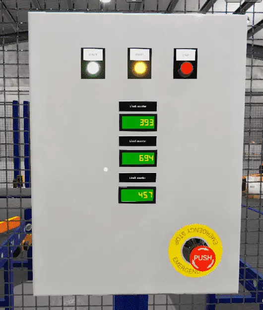
The control panel of the EasyPLC Box Selection Sorting Station program will show the operator information. If the gate is opened, the red LED will flash. In the stop mode, the green LED will be on, indicating this is how to start the line. When the line runs, the red LED will tell you how to stop the machine. An emergency stop will turn all of the LEDs off. The exit conveyor counts will show how many boxes have been diverted to it. When the machine stops, and the box counts are greater than 0, the reset LED will be on. Pressing the reset will zero the counts and turn off the LED.
A PLC programmer must know how everything about the sequence and operation of the machine before programming.
Ask questions or view existing documentation to ensure you know the logical steps to the machine’s operation.
Develop the PLC program: (Step 4 – Click PLC Sorting Station)
Writing the ladder logic code for our Click PLC sorting station example will be the next step in our program development.
We will use the Click PLC programming software and a Click PLUS CPU. Detailed information on the Click PLC can be found in our Click PLC Series. Our program will be written in ladder logic. (Ladder Diagram)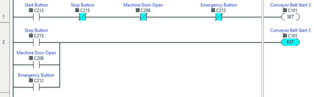
The first rungs of code will set the conveyor belts running for our box selection program. This is done with the set and reset instructions. The conveyor reset will happen when a stop, machine door, or emergency button is selected.
The start light will be on when the machine is ready.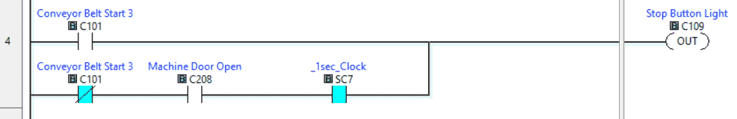
The stoplight will be on when the machine is running. A flashing stoplight will indicate that the machine is stopped and the door is opened.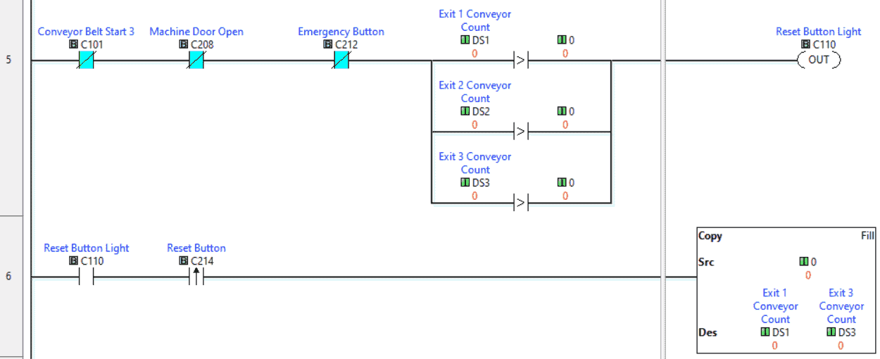
The reset button will be lit when the machine is stopped, and any exit conveyors have a count greater than 0. The reset button will reset the counts for each exit conveyor for the box selection program.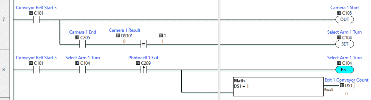
Exit 1 Conveyor
If the conveyors are running, the camera is turned on. The result is compared to the exit number when the camera end is seen. If this matches, then set the selection arm for the Exit. Once the photocell on the Exit is seen, reset the selection arm and increment the exit count by 1 for our box selection.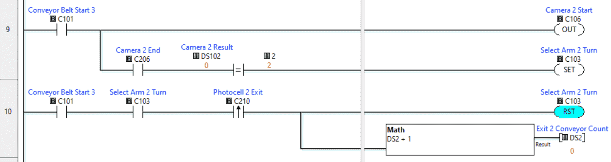
Exit 2 Conveyor
If the conveyors are running, the camera is turned on. The result is compared to the exit number when the camera end is seen. If this matches, then set the selection arm for the Exit. Once the photocell on the Exit is seen, reset the selection arm and increment the exit count by 1 for our box selection.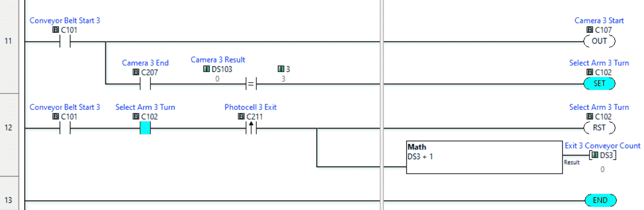
Exit 3 Conveyor
If the conveyors are running, the camera is turned on. The result is compared to the exit number when the camera end is seen. If this matches, then set the selection arm for the Exit. Once the photocell on the Exit is seen, reset the selection arm and increment the exit count by 1 for our box selection.
This is our complete program. See below to download the program and machine simulator scene.
We communicate to the EasyPLC machine simulator using Modbus TCP (Ethernet or Wireless). The ports will be set up with a fixed IP address so the machine simulator (Modbus Client) can find the Modbus Server.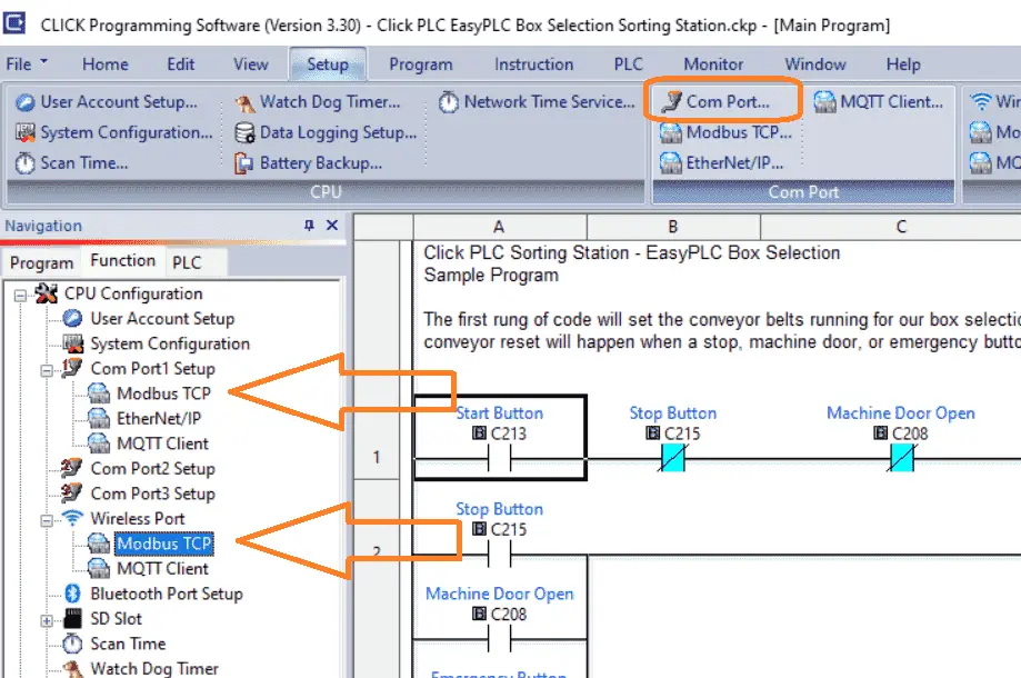
Select Modbus TCP from the communication port on the Function tab of the navigation window. You can also use the main menu | Setup | Com Port…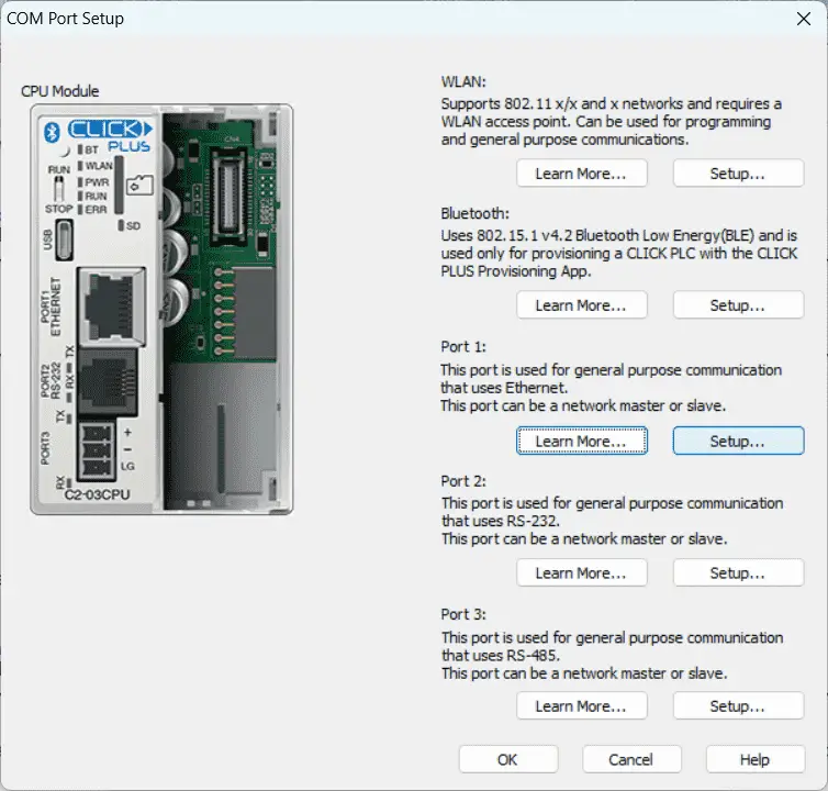
The COM port setup window will now be displayed. Click on the Setup Button for Port 1.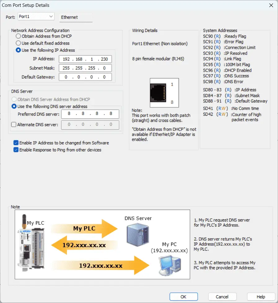
You can now set the static IP address on the Com Port Setup Details window.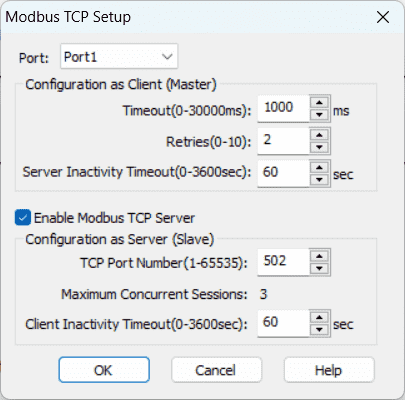
Select Modbus TCP Setup from the main menu | Setup. Ensure the “Enable Modbus TCP Server” is checked for our port.
Save and transfer the sorting station program to the Click PLUS PLC. Ensure that the PLC is in run mode. Select “Status” to see the active status of the inputs and outputs on the ladder logic.
Test the program: (Step 5 – Click PLC Sorting Station)
We will use Modbus TCP on our Click PLUS PLC to communicate with the machine simulator. Call up the “03 Box Selection” in start mode.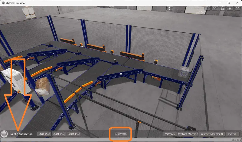
The status of the machine simulator will be at the bottom of the screen. Currently, we have no PLC connected. Select IO on the bottom middle of the screen.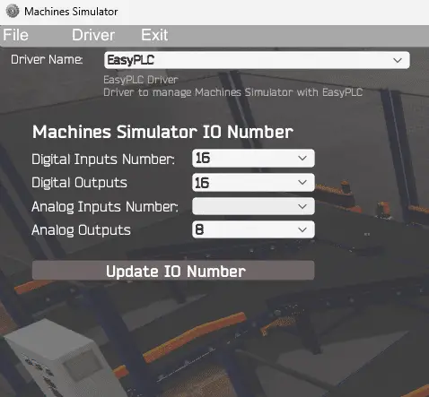
The EasyPLC driver window will now be displayed. This will show you the machine simulator IO number. Ensure you have enough digital and analog numbers for our Click PLC Sorting Station. If not, change the values and select the Update IO Number button.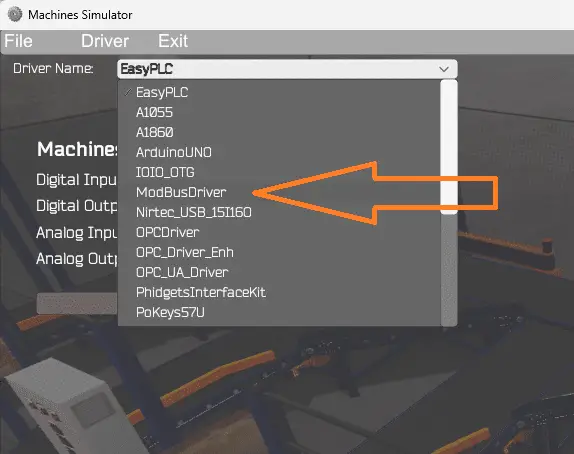
Under the driver name pull-down menu, select “ModBusDriver.”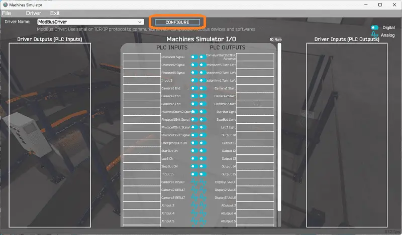
This driver will communicate Modbus TCP (Ethernet) and Modbus RTU (Serial). Select the configure button.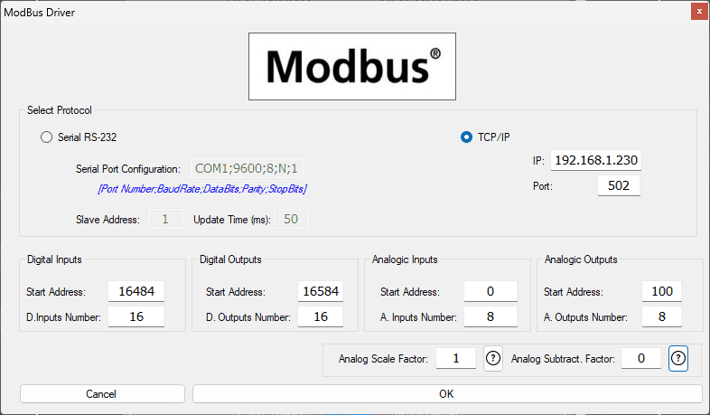
We can now enter the information for our Modbus driver. Select TCP/IP. This means the computer’s Ethernet port will communicate with the PLC. The digital inputs from MS to the Click PLC will start at C101. This will start at address 16484 due to the offset of 1. Digital outputs from MS to the Click PLC will start at C201. This will begin at address 16584 due to the offset of 1. Analog inputs DS1 will start at address 0, and outputs DS101 will begin at address 100. This is due to the offset of 1. The address picker in the Click programming software will help determine the Modbus Addresses.
The analog scale factor is 1. This is used to divide and multiply so that the Modbus analog value can be read/written within the simulator. The analog subtract factor is 0. This is used with the analog to obtain negative numbers within the Modbus analog registers.
Select the OK button.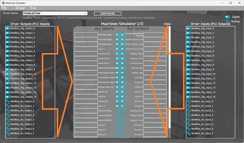
You will now see the inputs and outputs specified for the Modbus driver. We can now manually assign the driver outputs to the PLC inputs and driver inputs to the PLC outputs. However, an automatic assignment will do this if the I/O is in the same order in the PLC and EasyPLC machine simulator.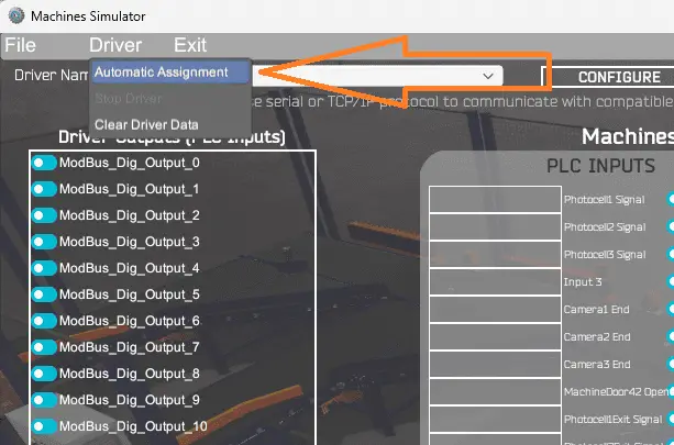
Select Automatic Assignment from the driver option in the main menu.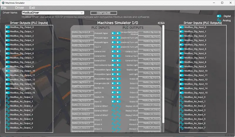
This will automatically assign the PLC IO to the Machine Simulator IO.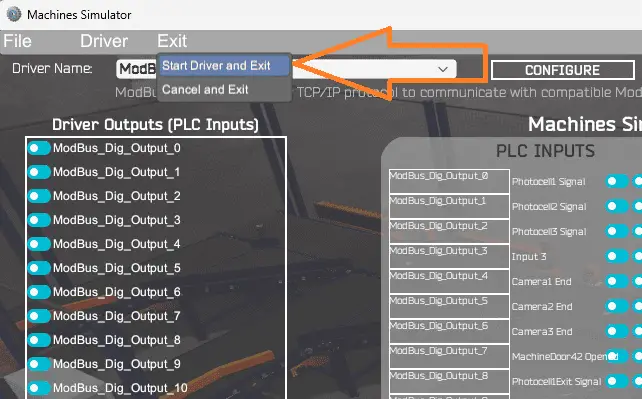
Select “Start Driver and Exit” from the main menu under Exit.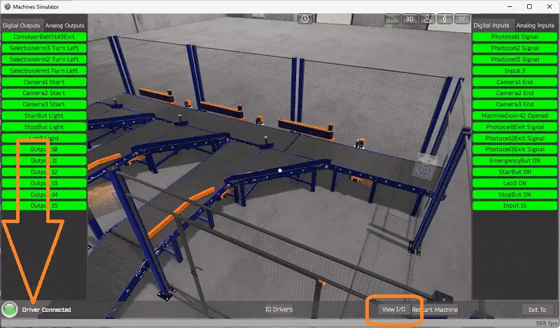
You will see that the driver is operating on the bottom left side of the window. Select view IO to know the input and output status of the machine simulator. Move around to the control panel.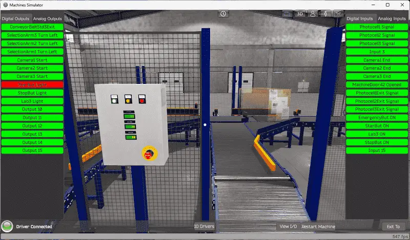
Ensure that the PLC is in run mode. We can now operate the machine simulator through the control panel.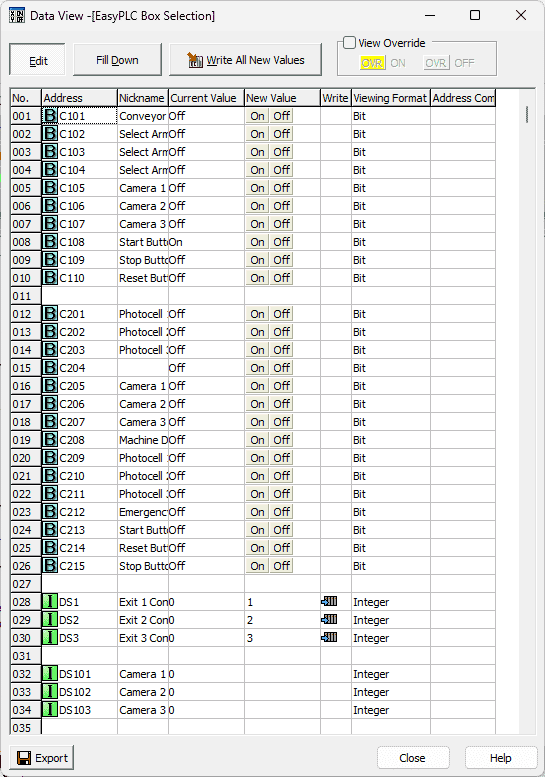
Using the Data View window of the Click programming software, we can also watch the inputs and output operations.
Run and monitor to ensure that your program works as expected.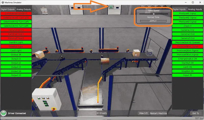
Using Machine Simulator (MS) to test the program will ensure that our program works. Troubleshooting is quickly done without damage to any physical hardware.
The machine simulator has a time frame that you can speed up or slow down the process to help you troubleshoot. Watch the video below to see this operation.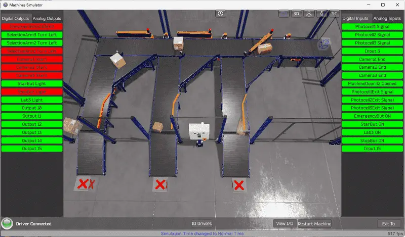
Download the Click PLC sample program for the Click Sorting Station.
Watch the video below to see the five steps of program development applied to the Click PLC Sorting Station Box Selection. The machine simulator is the best application to help you learn PLC programming.
EasyPLC Software Suite is a complete PLC, HMI, and Machine Simulator package. This PLC learning package includes the following:
Easy PLC – PLC Simulation allows programming in Ladder, Grafcet, Logic Blocks, or Script.
HMI System – Easily create a visual human-machine interface (HMI)
Machine Simulator – A virtual 3D world with real-time graphics and physical properties. PLC programs can be tested using EasyPLC or through other interfaces. (Modbus RTU, TCP, etc.)
Machine Simulator Lite – Designed to run on Android Devices.
Machine Simulator VR – Virtual Reality comes to life so you can test, train or practice your PLC programming.
Purchase your copy of this learning package for less than USD 75 for a single computer install or less than USD 100 to allow different computers.
Receive 10% off the price by typing in ACC in the comment section when you order. http://www.nirtec.com/index.php/purchase-price/
Learn PLC programming the easy way. Invest in yourself today.
Watch on YouTube: How to Program a Sorting Station – Click PLC
If you have any questions or need further information, please contact me.
Thank you,
Garry
If you’re like most of my readers, you’re committed to learning about technology. Numbering systems used in PLCs are not challenging to learn and understand. We will walk through the numbering systems used in PLCs. This includes Bits, decimals, Hexadecimal, ASCII, and Floating points.
To get this free article, subscribe to my free email newsletter.
Use the information to inform other people how numbering systems work. Sign up now.

The ‘Robust Data Logging for Free’ eBook is also available for free download. The link is included when you subscribe to ACC Automation.