How Ladder Logic Program Scan Works

How Ladder Logic Program Scan Works

PLC programs scan cyclically. This means that it is repeated many times and in the same order. The primary sequence of a PLC scan is reading the inputs, executing the program, diagnostics, and communication, and updating the outputs. We will look at these scan items with particular attention to how the ladder logic program is … Read more

3 Steps to PLC Programming – Learning

3 Steps to PLC Programming - Learning

You’ve had this idea for years since you were a kid. You want to be an electrical engineer, and you’re finally going to follow through on it and learn PLC programming to start your career off right! What? That’s what you thought, anyway. But then you started googling around, trying to figure out how to … Read more

Timing Diagram NOT Just Used for a Timer

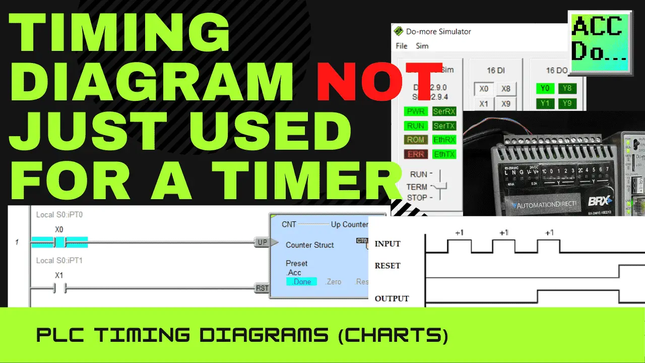
Logic circuits in a PLC ladder logic program are either on or off. The inputs change, which will affect the outputs. This can be expressed in a timing diagram. The timing diagram or chart will show you how the ladder logic program will respond to the changing states of the inputs and outputs. This visual … Read more

PLC Learning Series – Programming Steps

PLC Learning Series – Programming Steps

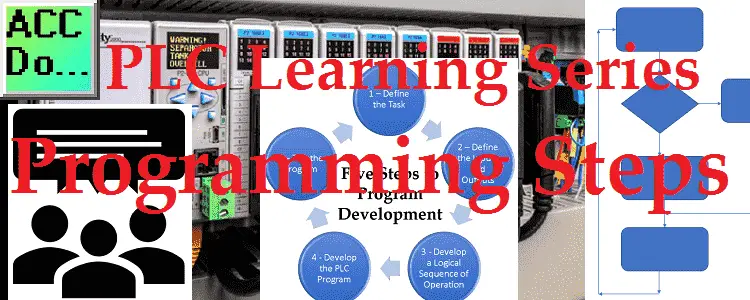
Developing a programmable logic controller (PLC) program can be broken down into five steps. These programming steps are as follows: Five Steps to PLC Program Development Step 1 – Define the task Step 2 – Define the Inputs and Outputs Step 3 – Develop a logical sequence of operation Step 4 – Develop the PLC … Read more

PLC Learning Series – Program Cyclic Scan

PLC Learning Series - Program Cyclic Scan

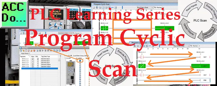
Programmable logic controllers (PLC) use a cyclic scan. The time that it takes to complete one scan is called Scan Time. Typical scan times range from 10 milliseconds to 10 microseconds. This translates from 0.01 to 0.0001 seconds per PLC scan. Understanding how the program scan will help us in programming and troubleshooting the PLC. … Read more

PLC Learning Series – Understanding Numbers

PLC Learning Series - Understanding Number Values

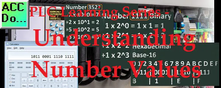
All programmable logic controllers (PLC) have the same numbering system at their core. This is the same with all computers as well. The status of any memory location can be either on or off. A one (1) will represent an on or “True” status and zero (0) will represent an off or “False” status. This … Read more