Arduino Opta Software Installation
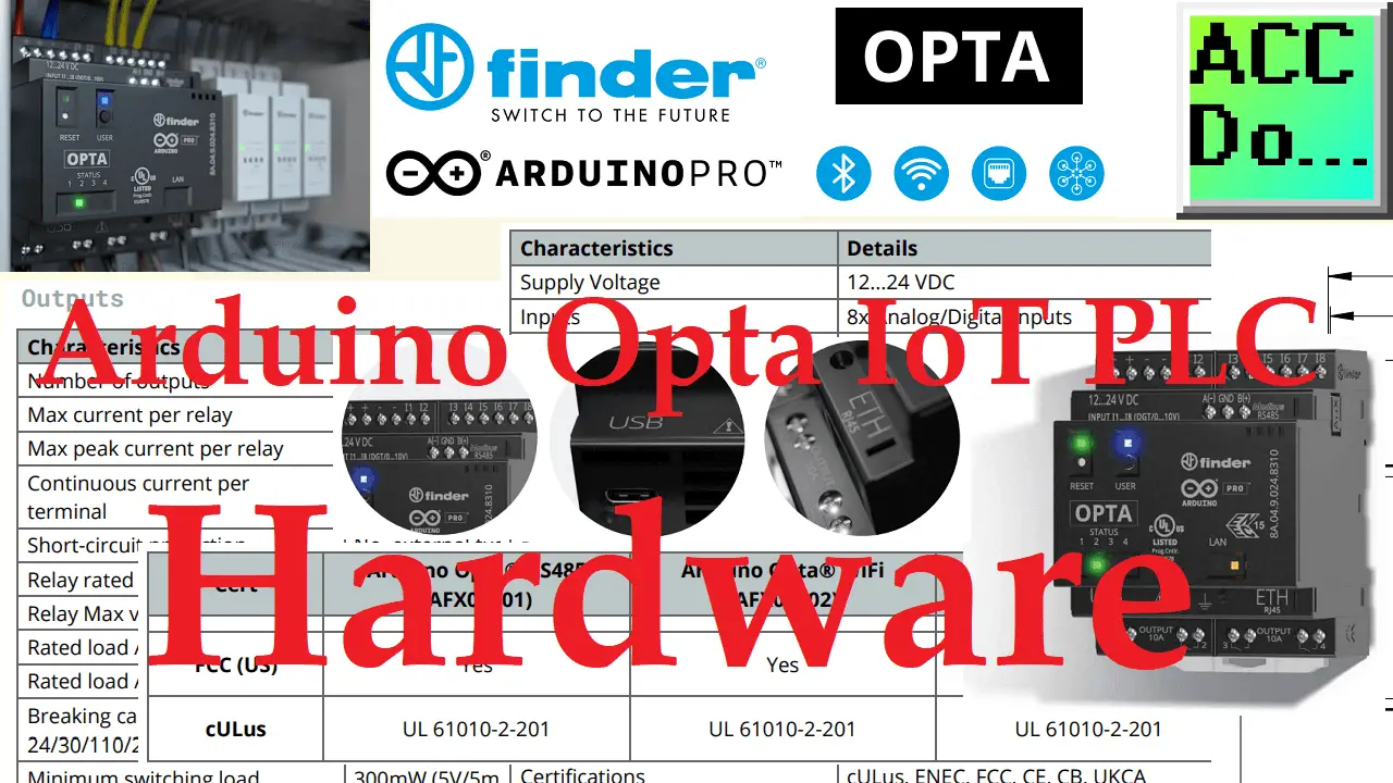
The Arduino Opta can be programmed with basically two different software packages. The Arduino IDE and the Arduino PLC IDE. Arduino IDE is the traditional programming package for sketches (programs). C++ is used in sketches to develop your logic. Arduino PLC IDE will transform the Arduino Opta into a micro-PLC controller. Programs can be written … Read more