Tag Database Tutorial for Automation Direct Mini PLCs!
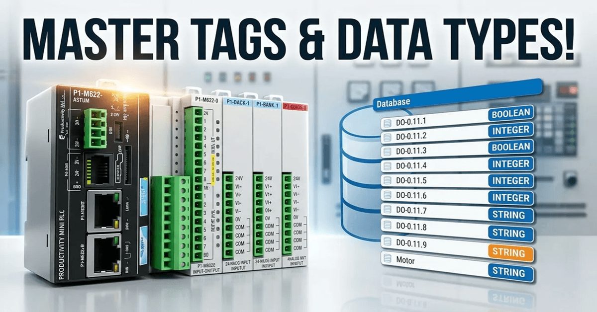
We will now look at the tag numbering systems used with the Productivity Mini PLC P1-M622-16DR. The Productivity Suite Software allows us to use tags in the PLC. Tags are a method for assigning and referencing memory locations (numbering systems) within the programmable logic controller. They allow a more structured programming approach and are stored … Read more